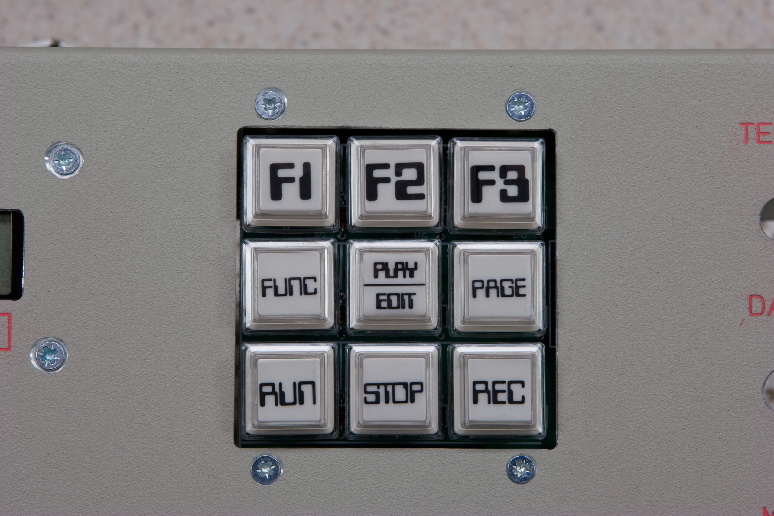
Failing PLED?
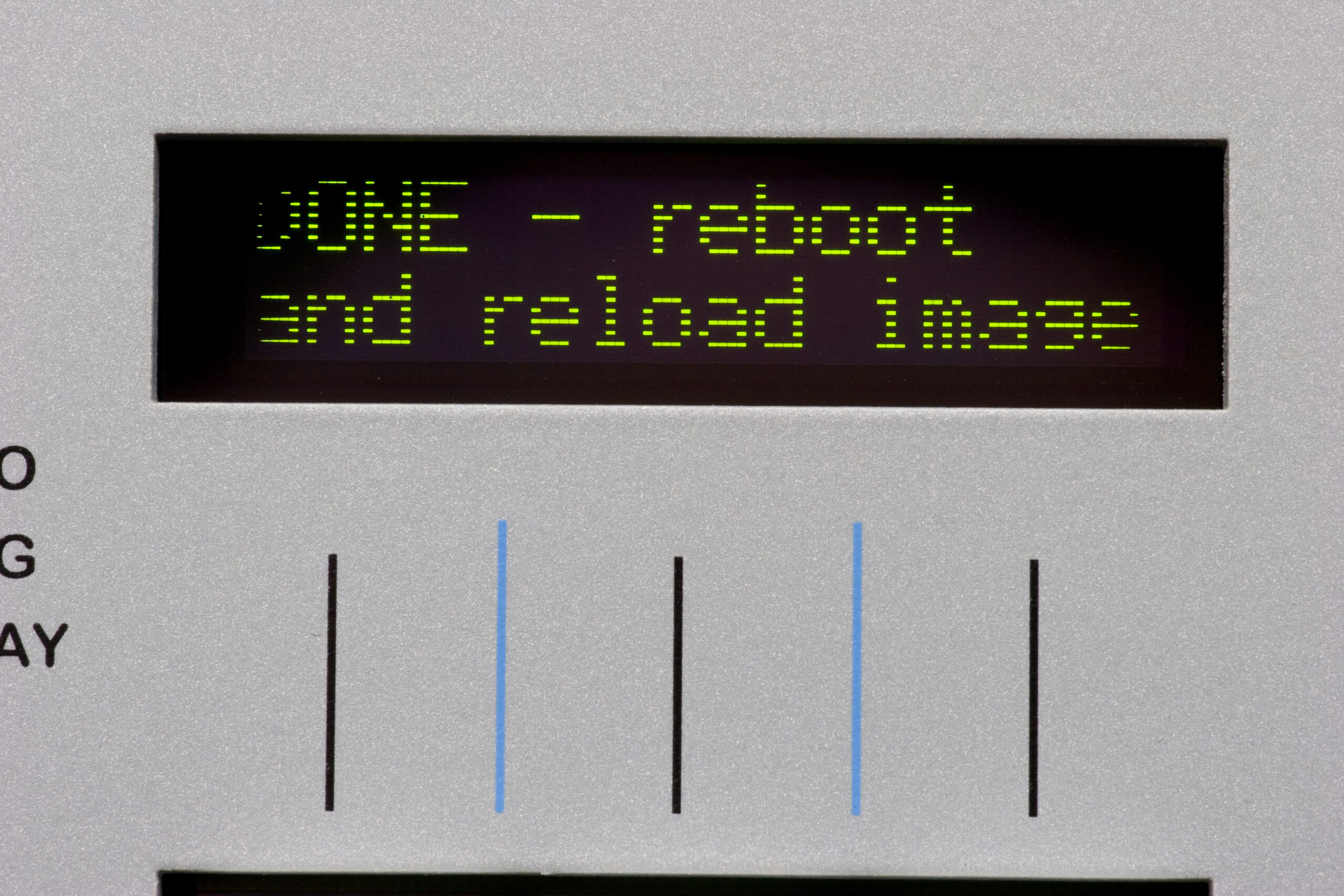
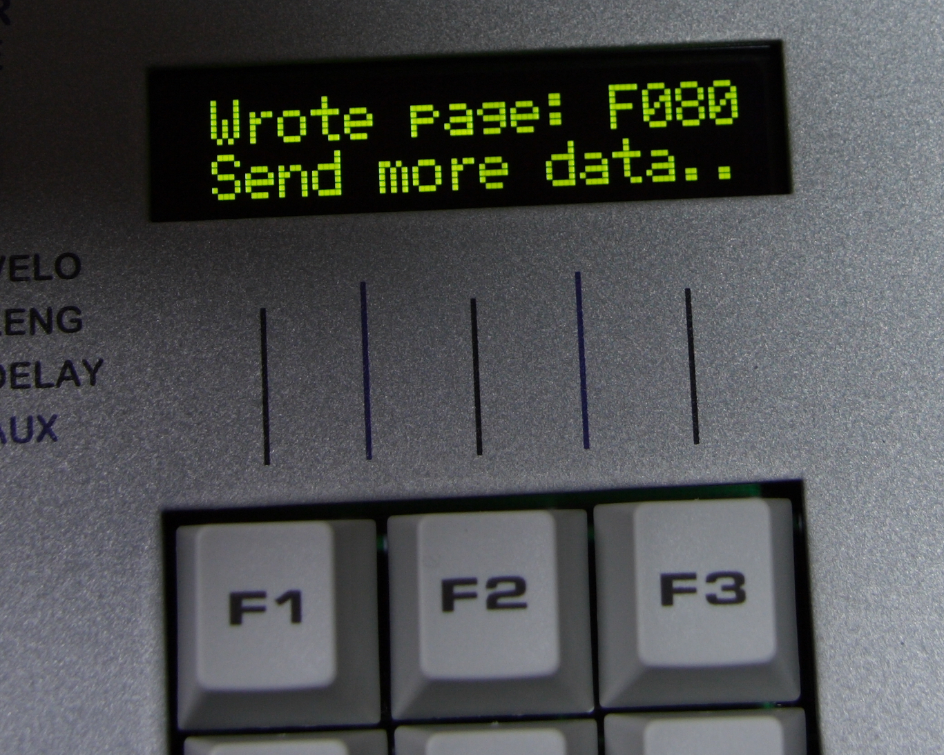
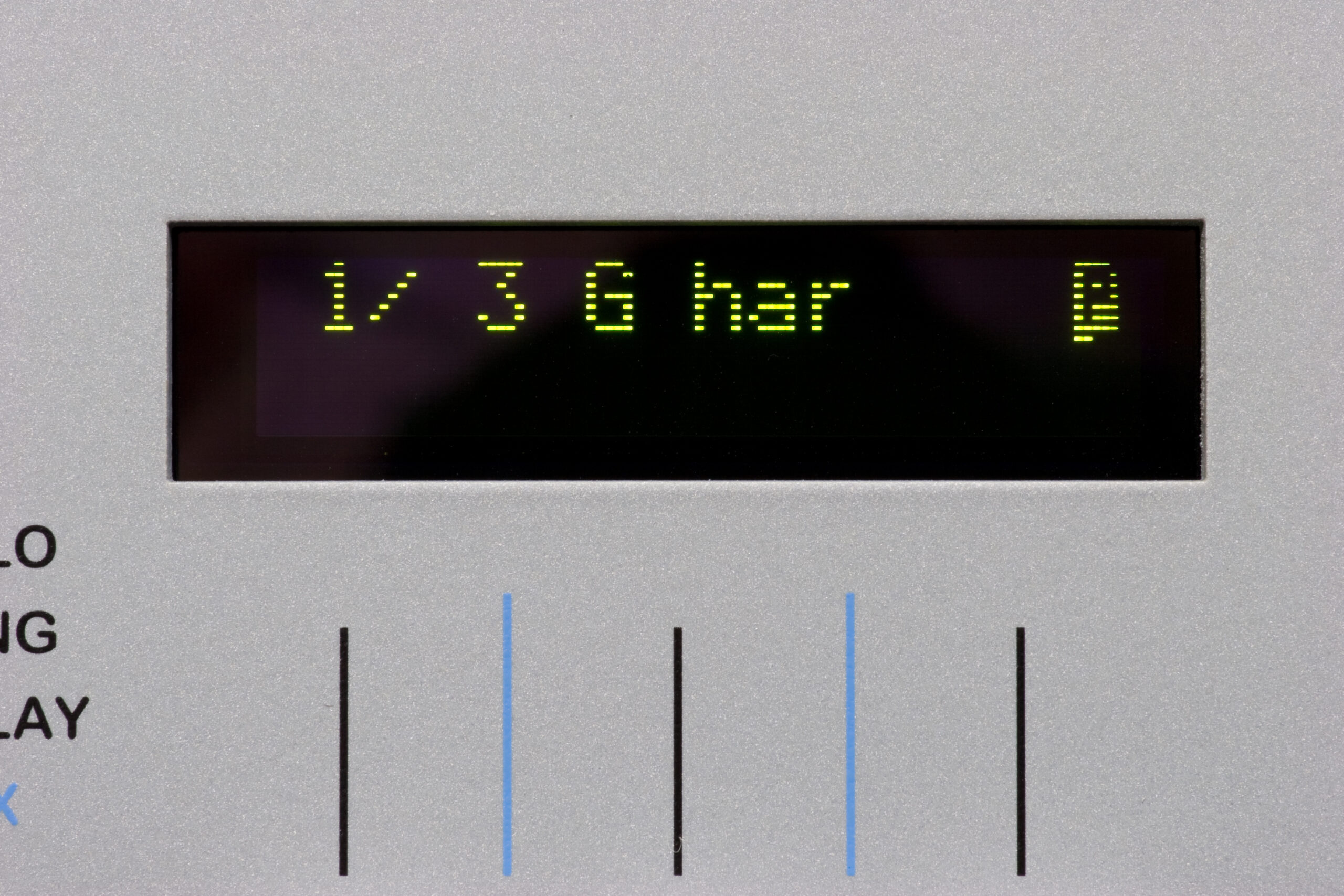
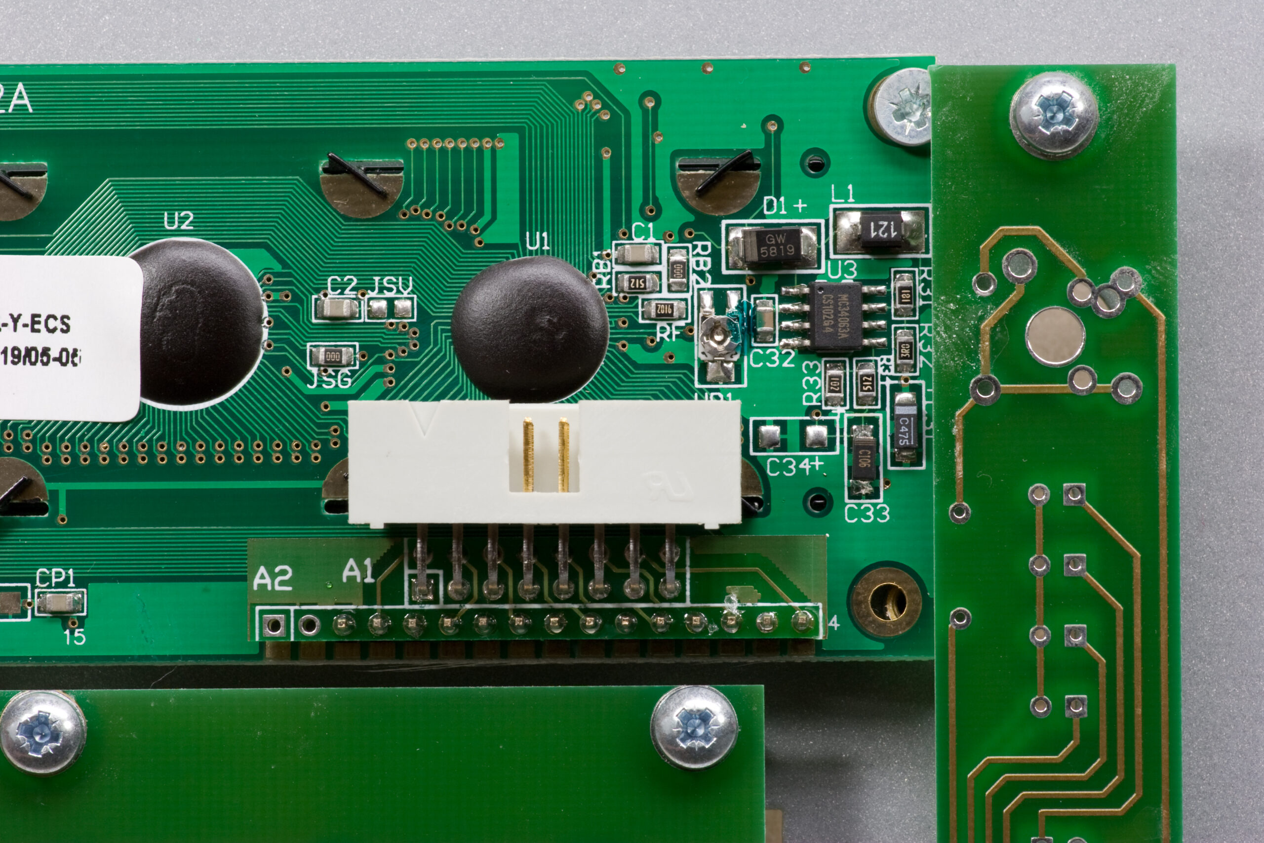
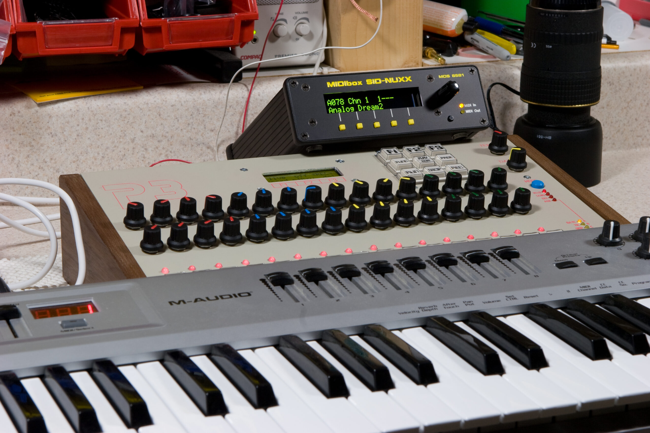
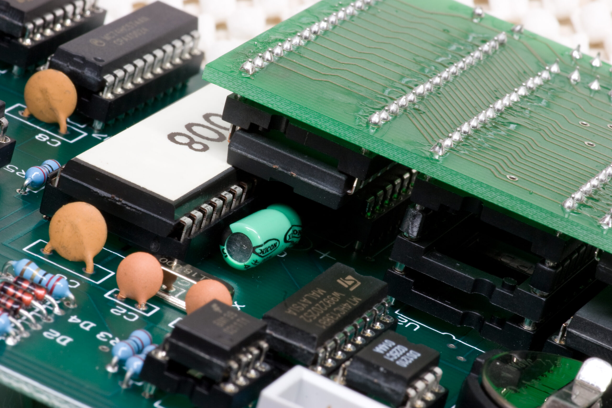
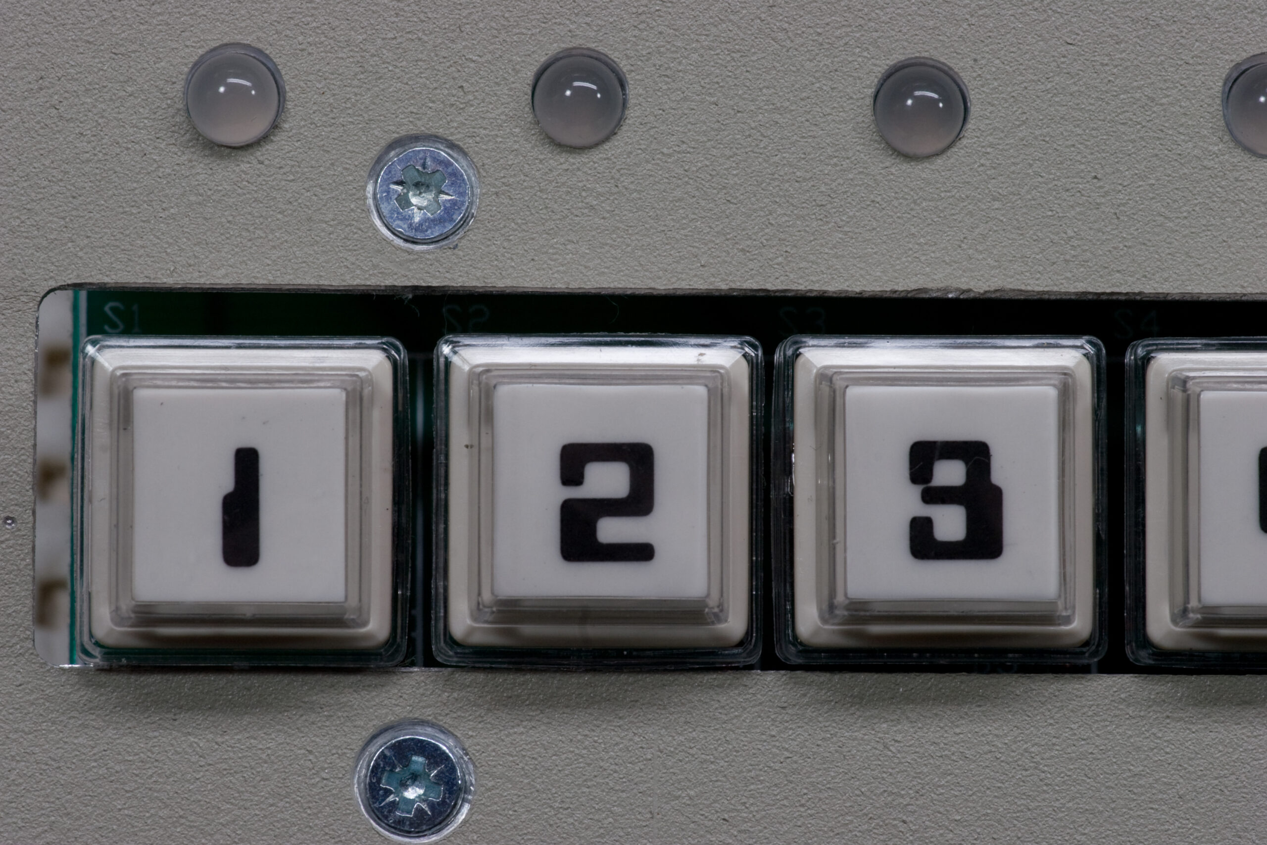
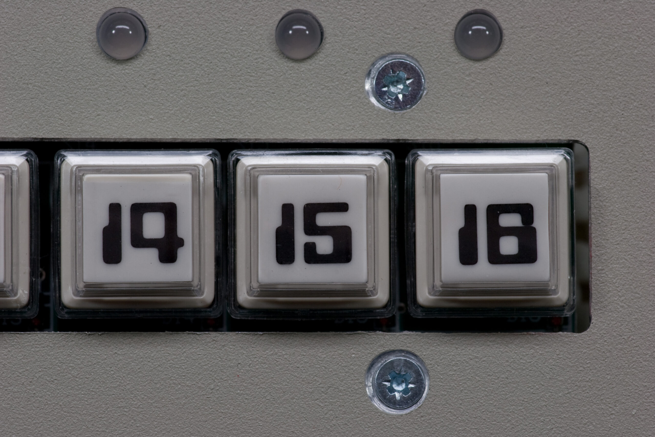
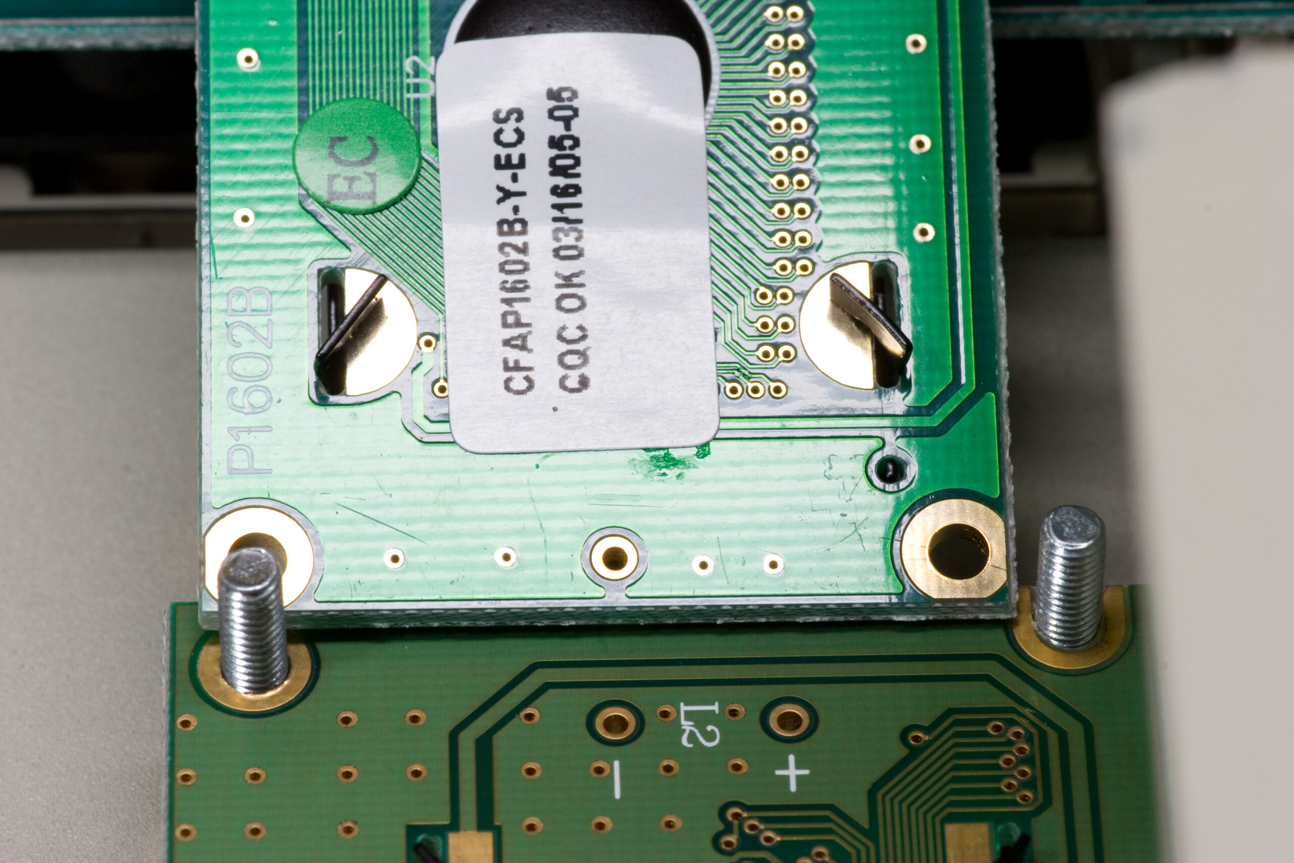
Last night I made quite a bit of progress on Ivan’s P3 (photo gallery retired), getting it up and running, but I did run into a few problems. First, as can be seen above, the PLED which came with the enclosure seems to be failing. It will either display no text, one line of text, or (rarely) both lines, and every time pixels seem small and dim, with the edges of the display fading to nothing. Only a power cycle of the P3 seems to (re-)activate non-working parts of the display. As the P3 still functions even when nothing appears on the display, I believe that it’s actually the display elements of the PLED which is failing.
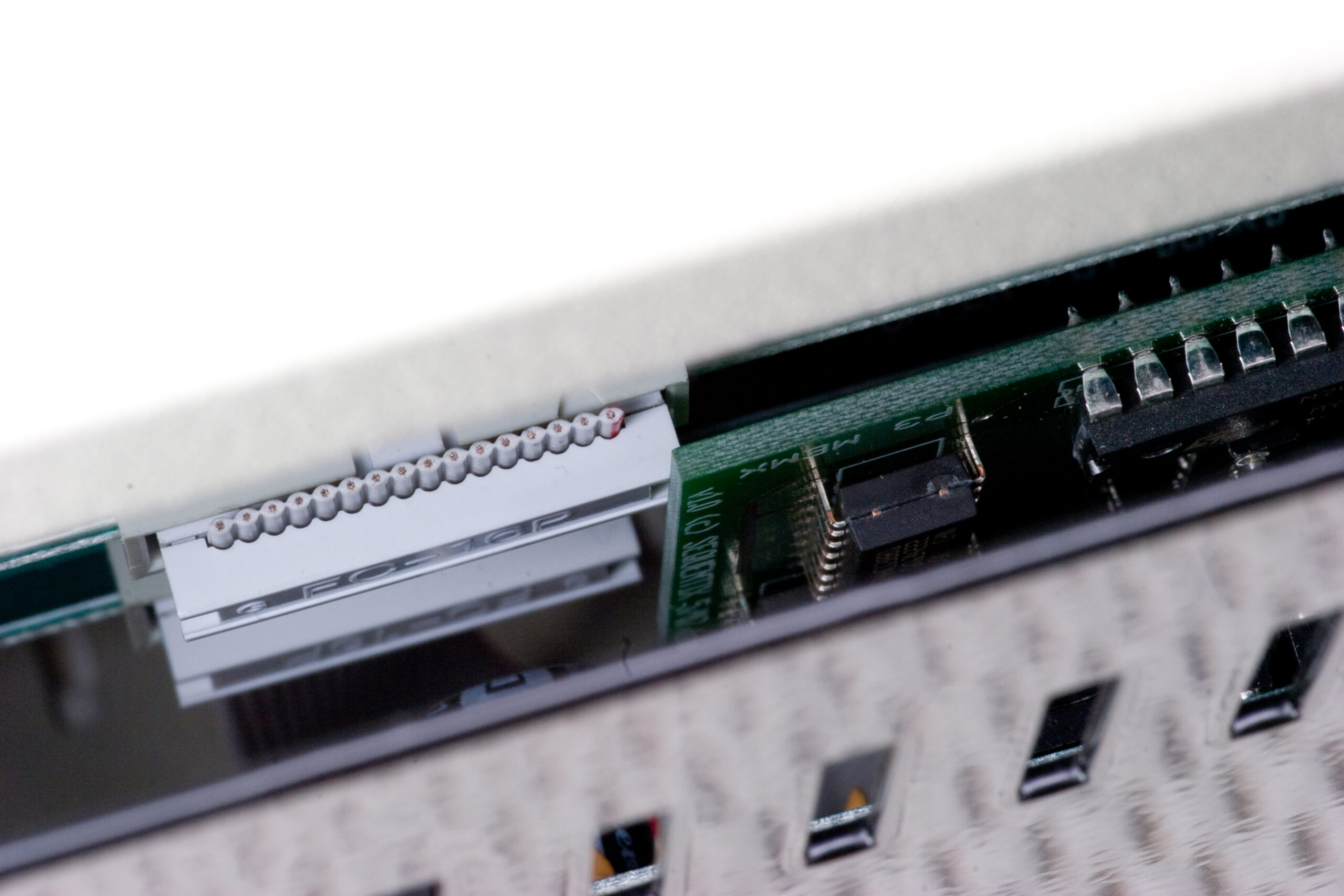
Here is the PLED in my P3 from 2006, and when it is compared with these two images (1, 2) of the PLED from Ivan’s P3, it seems pretty obvious that something is wrong.
Thankfully there was a spare PLED in the package of parts I received, so tonight I’m going to try that one instead.
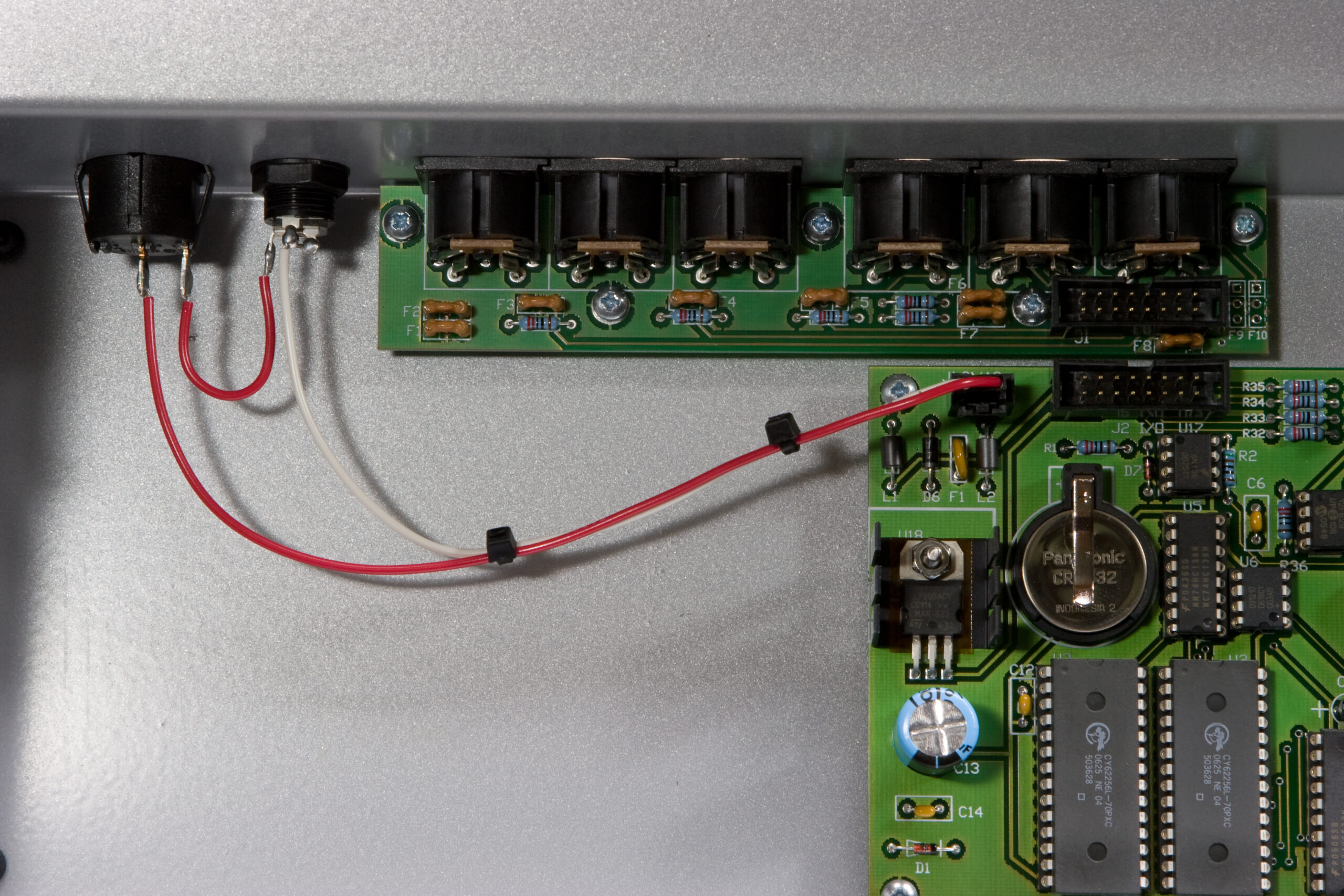
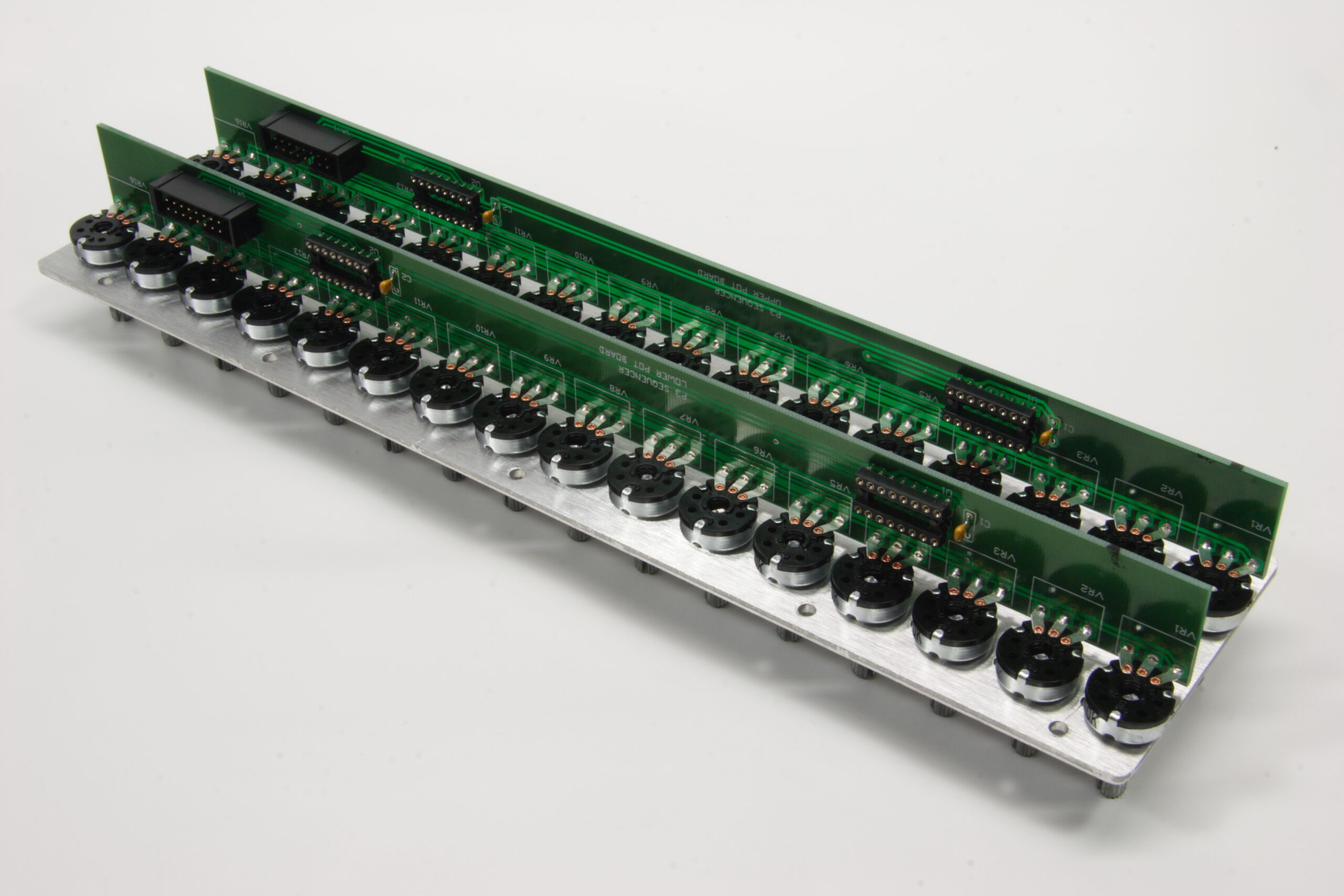
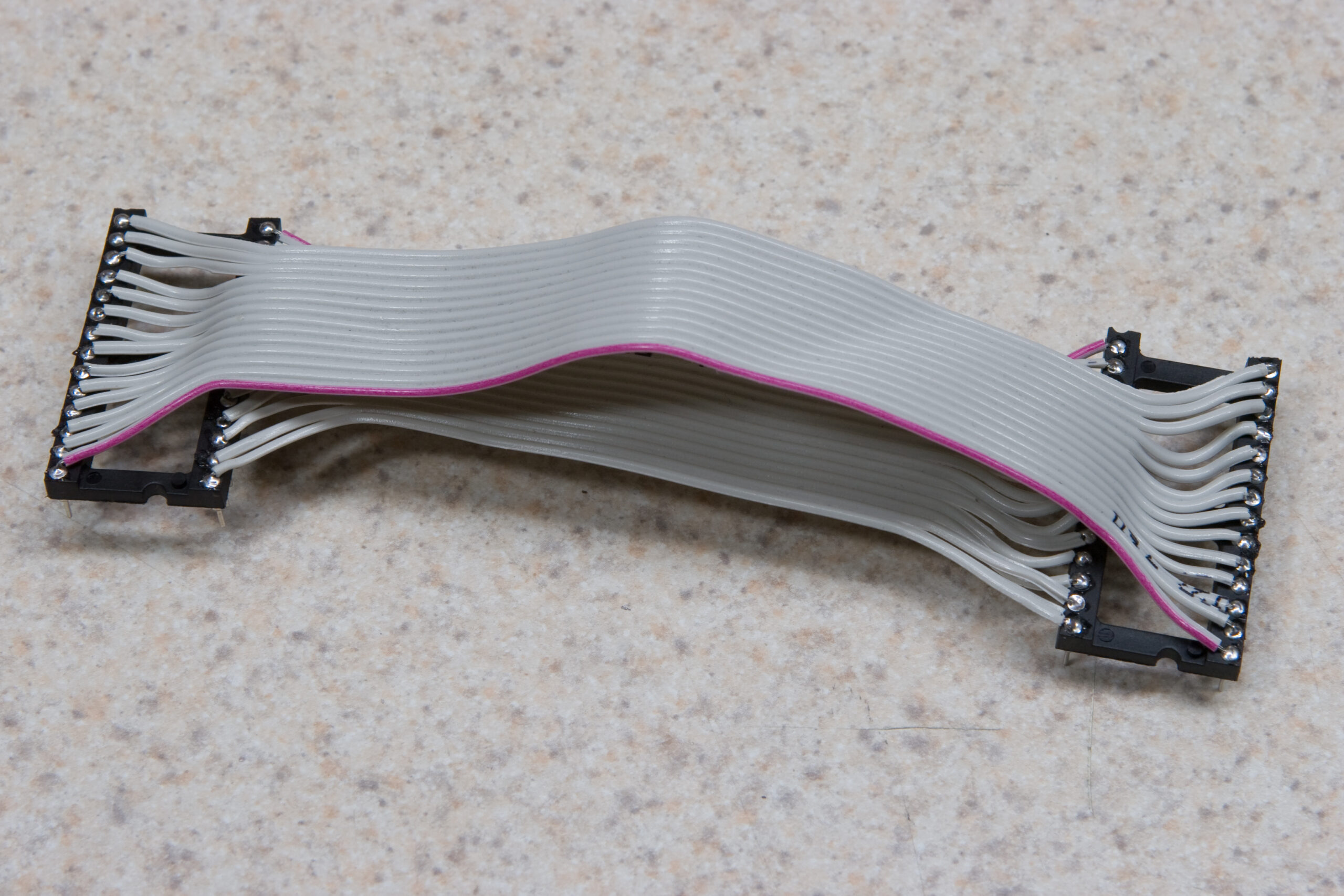
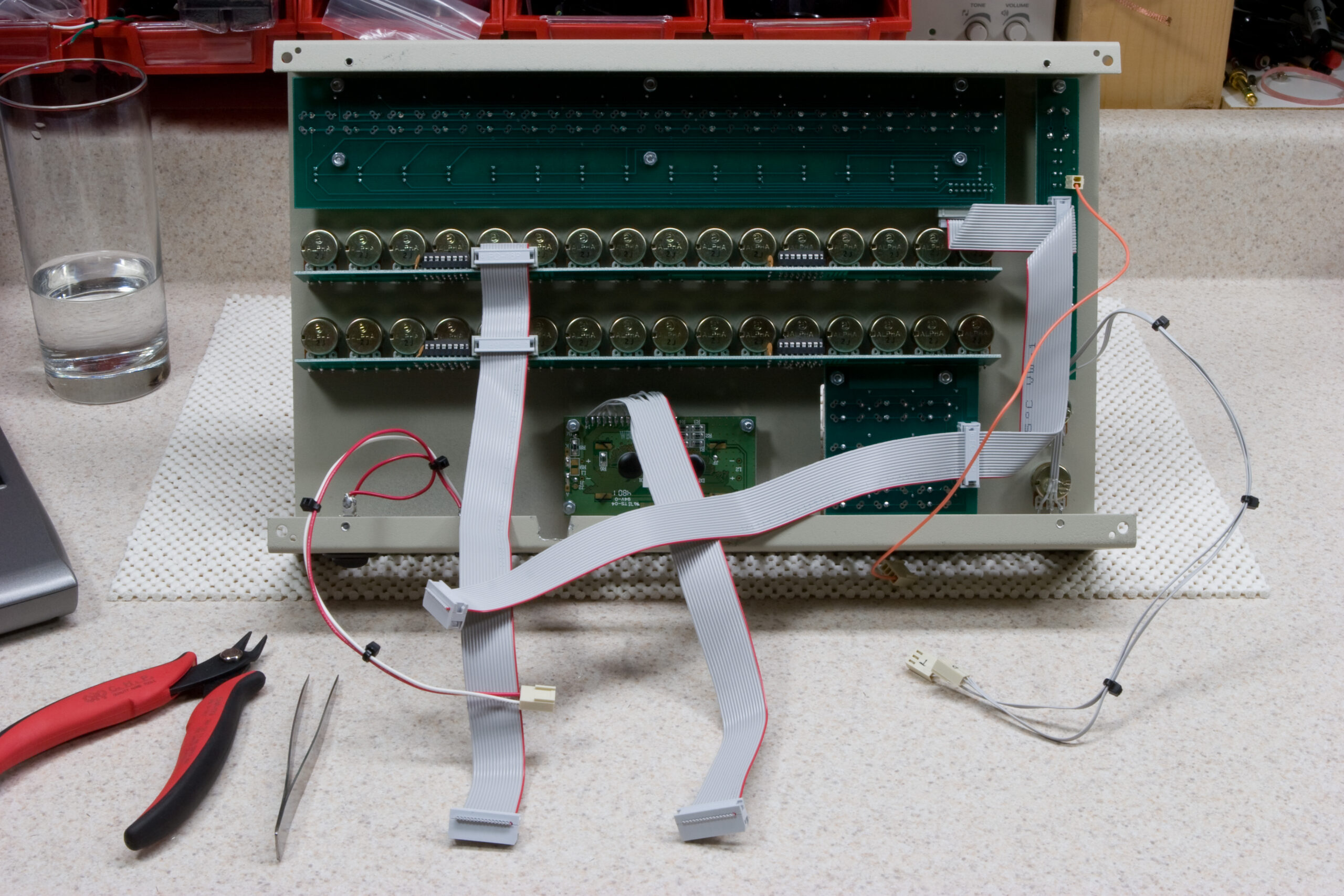
Second, I’m not happy with the cables I made for connecting the tempo and data pots to the mainboard, so I’m going to remake them. The tempo pot connection seems to be a bit flaky, so I’m not sure the pins are properly seated in the connector. The cables are also short enough that they are difficult to connect, so I’ll probably redo them with braided 24 gauge hookup wire or something like that.
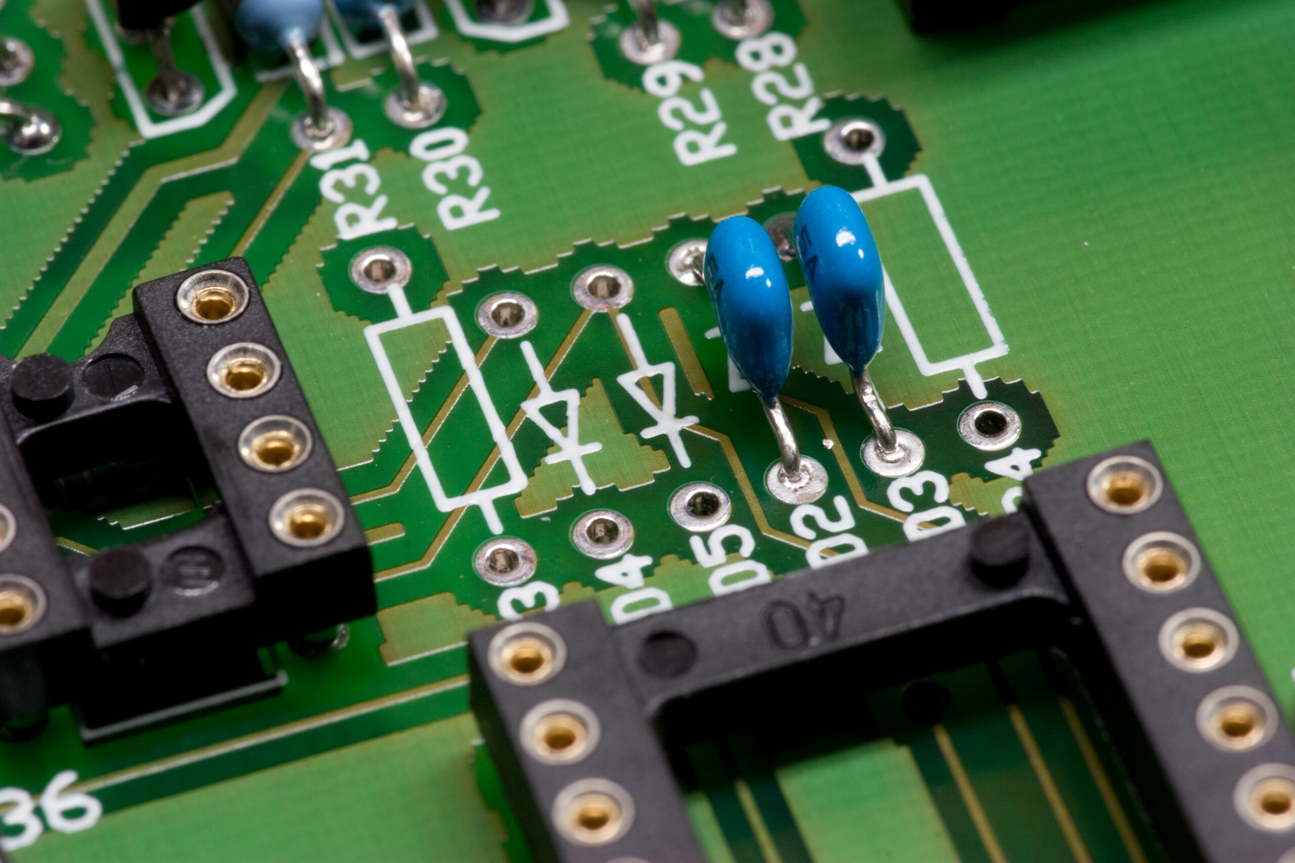
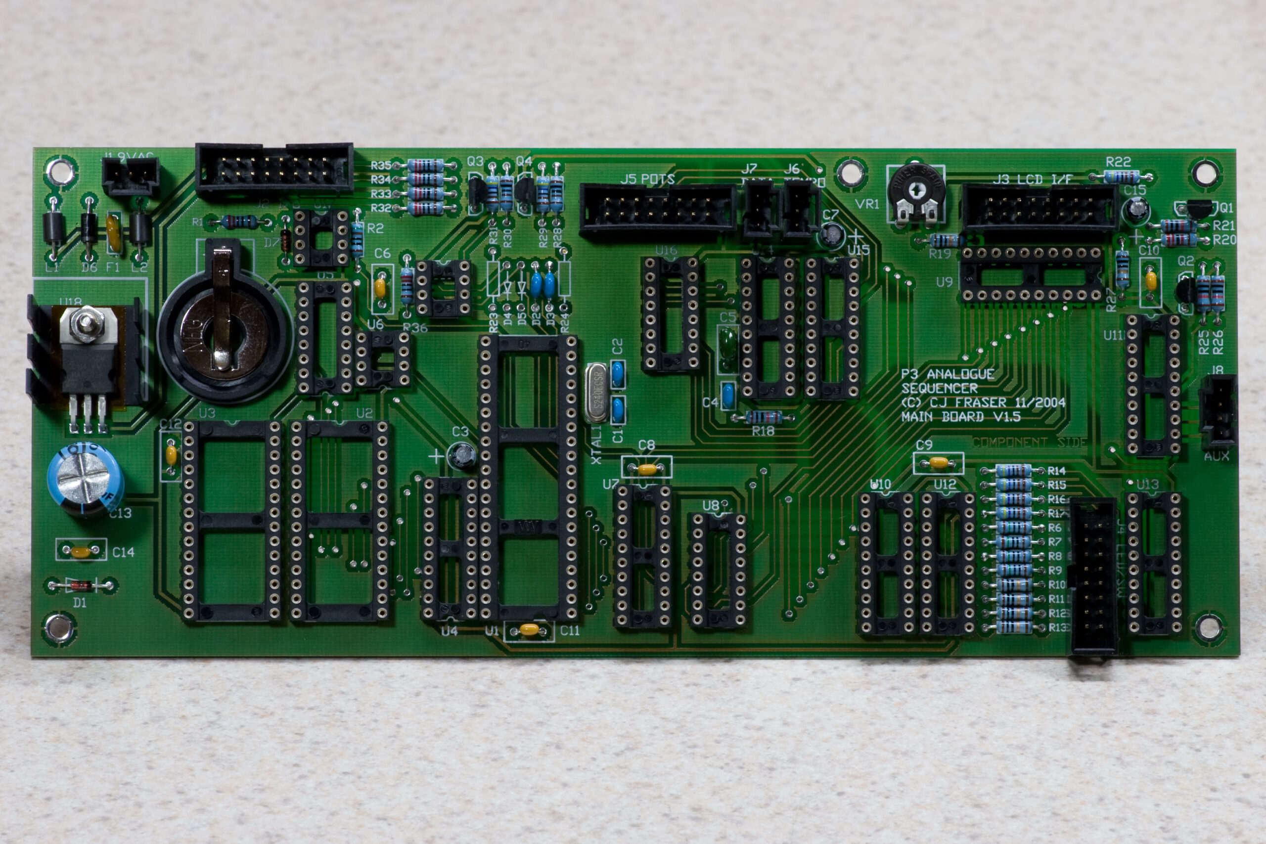
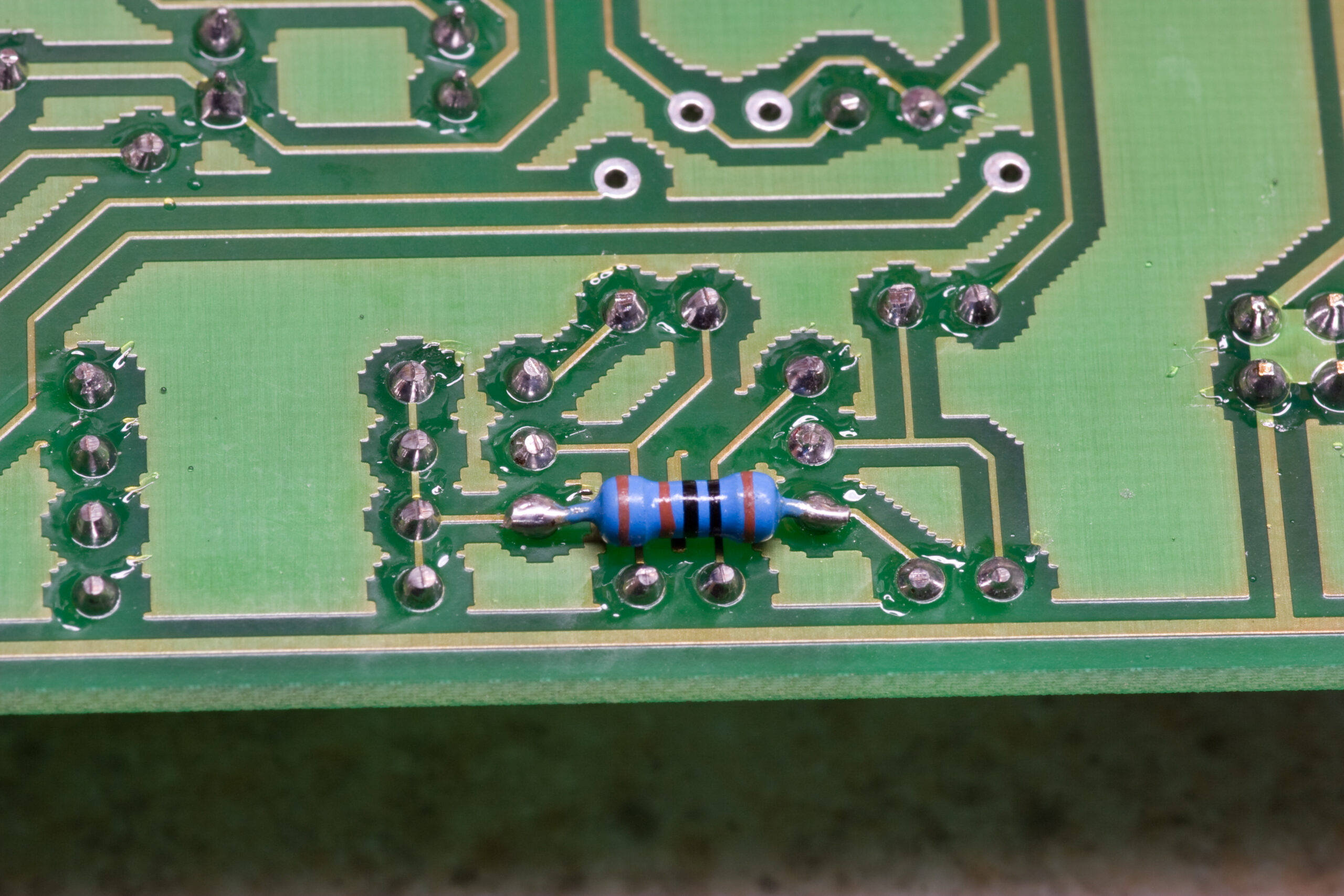
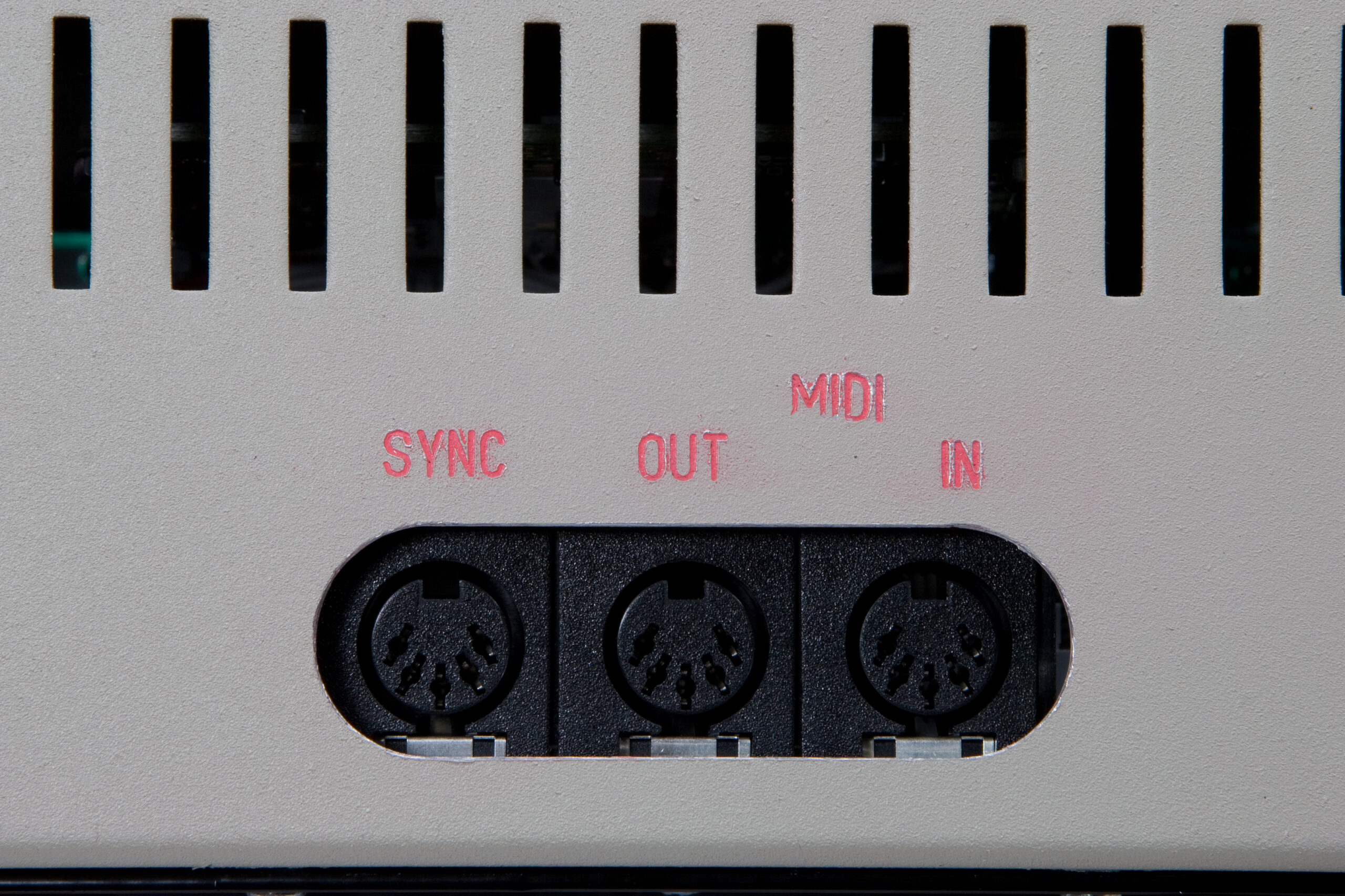
Finally, the v1.5 mainboard construction notes indicate that when the P3 is being set up for MIDI sync, D2 and D3 should be replaced with 220pF caps in order to add a bit of extra capacitance to the lines to work around false triggers. I didn’t have any 220pF parts, and none came with the kit, so I instead used 330pF parts. I don’t believe this will be a problem, but I made a post to the analogue-sequencer group asking for confirmation.
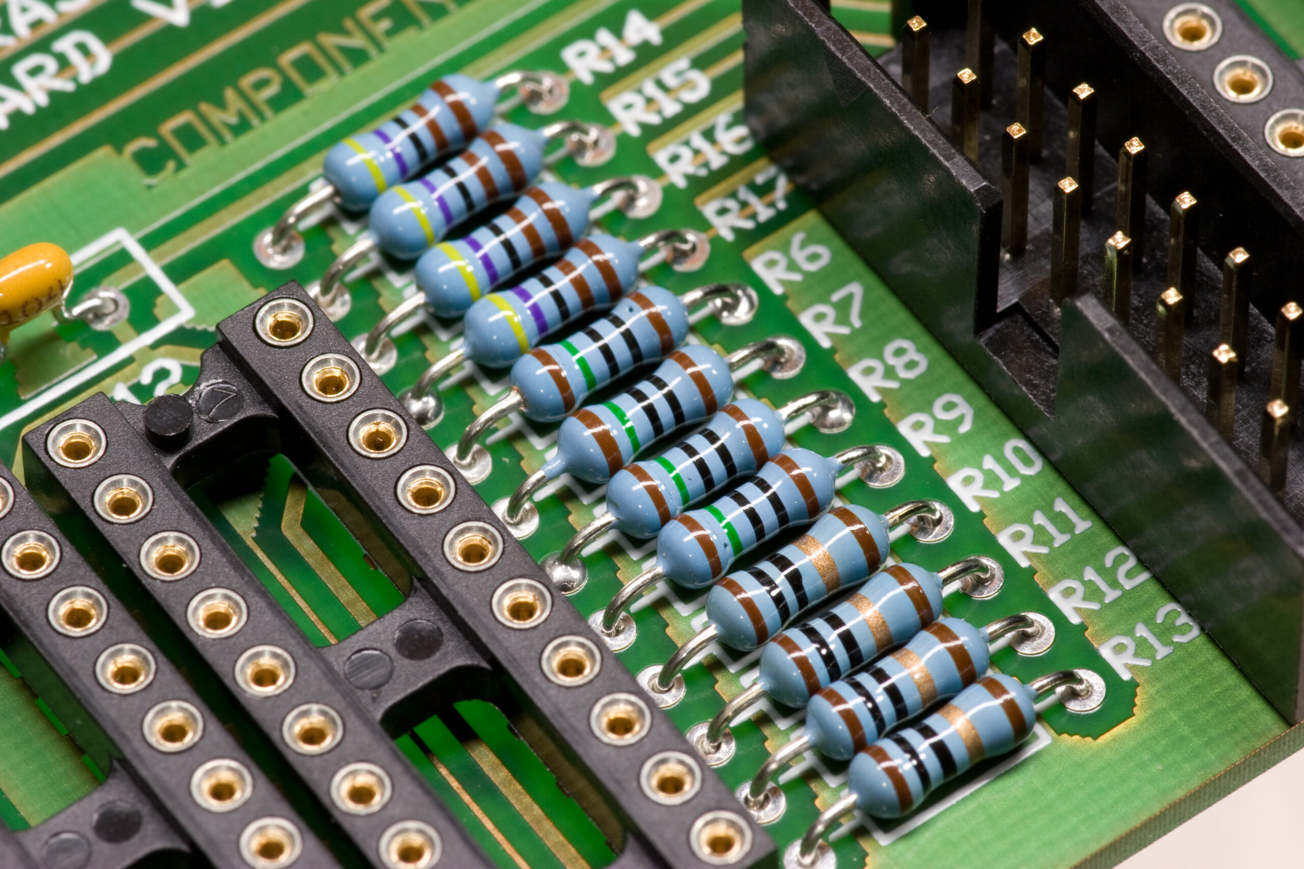
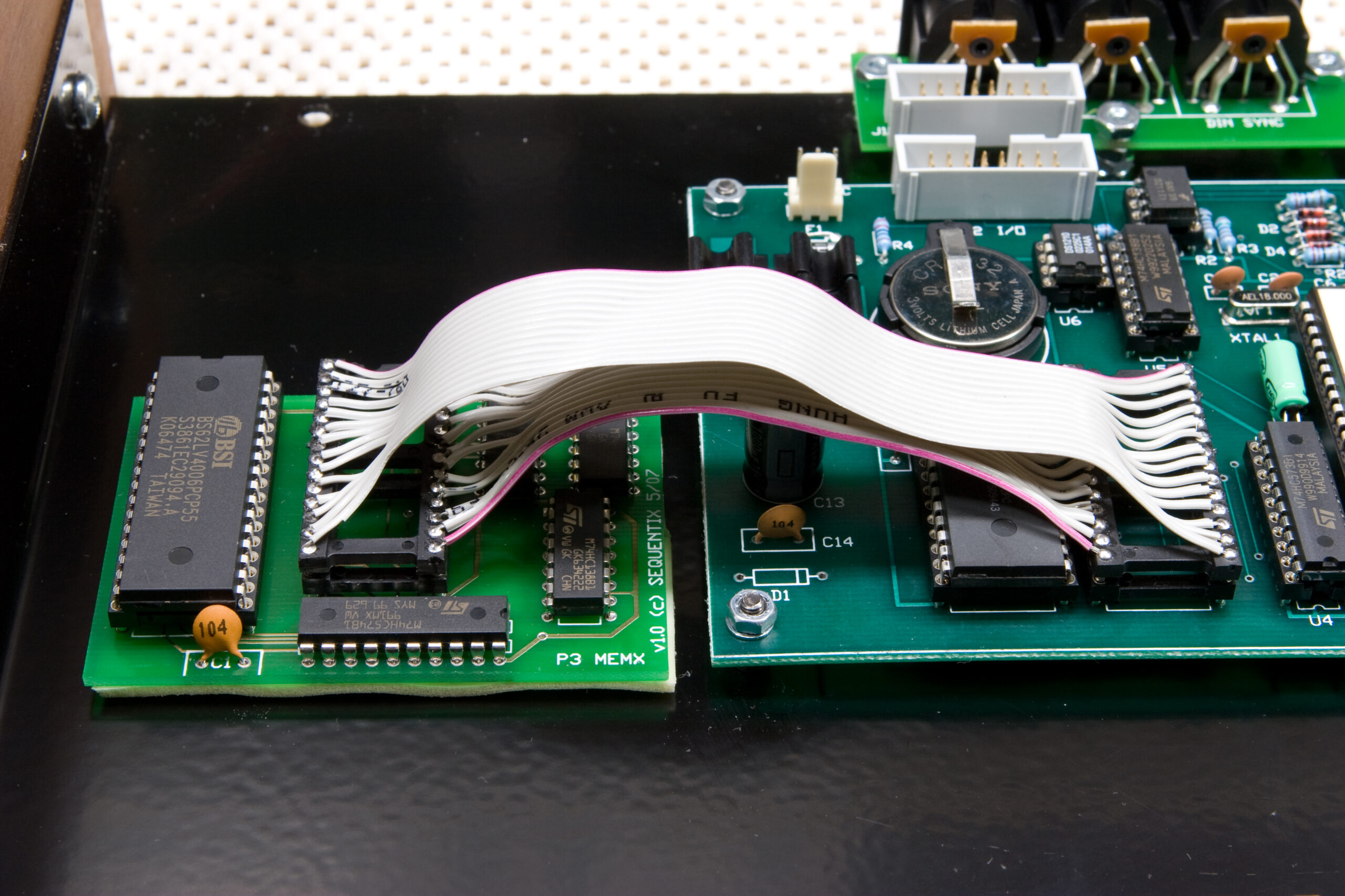
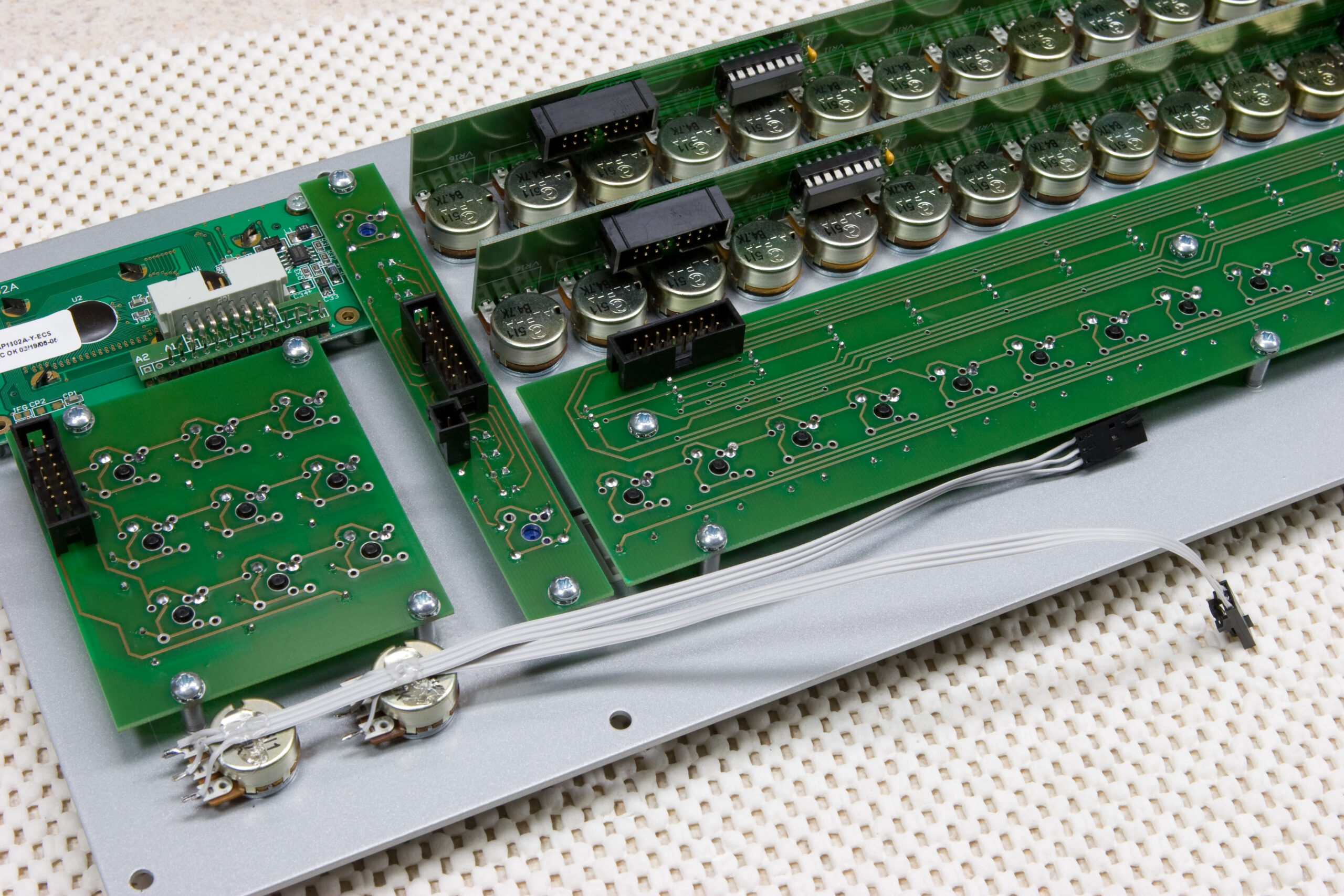
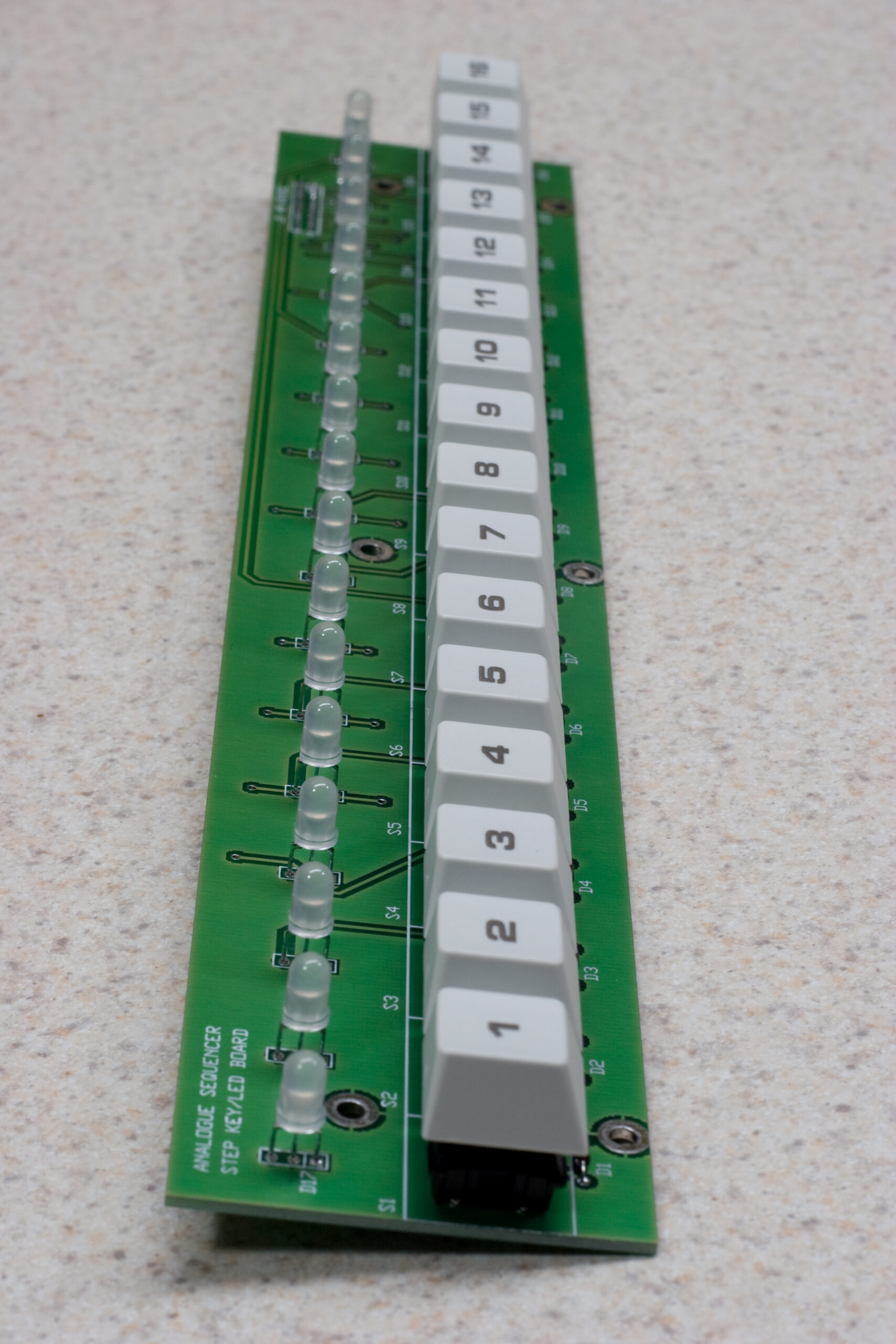
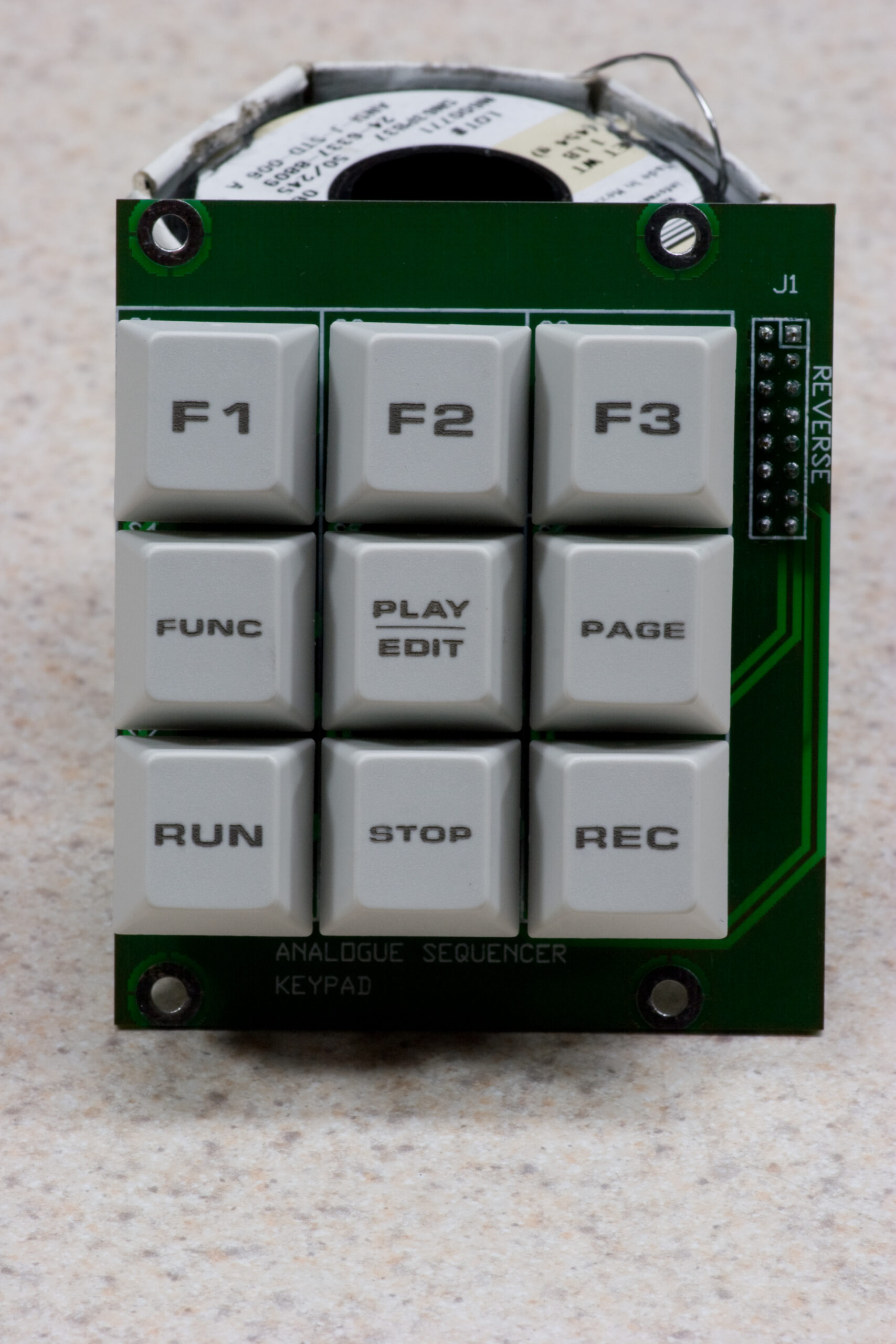
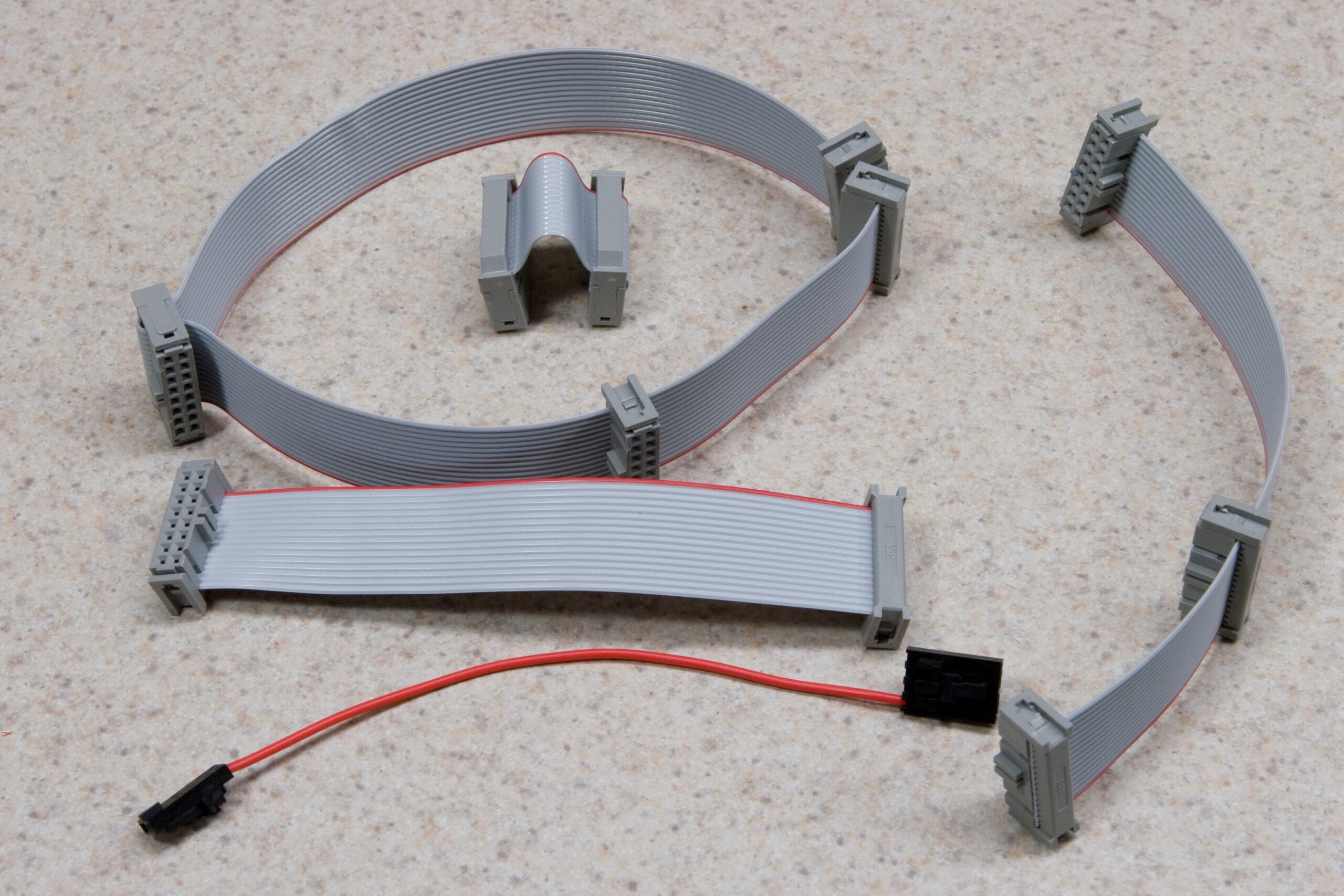
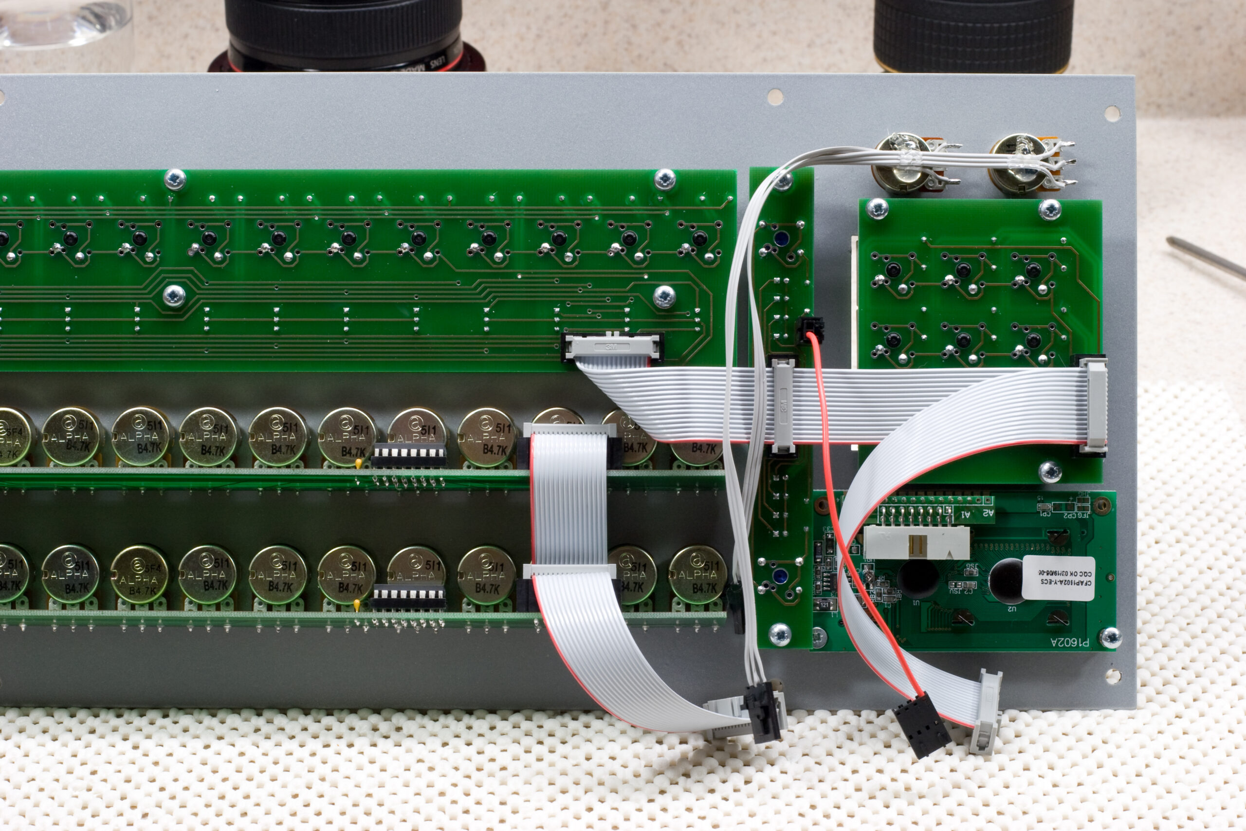
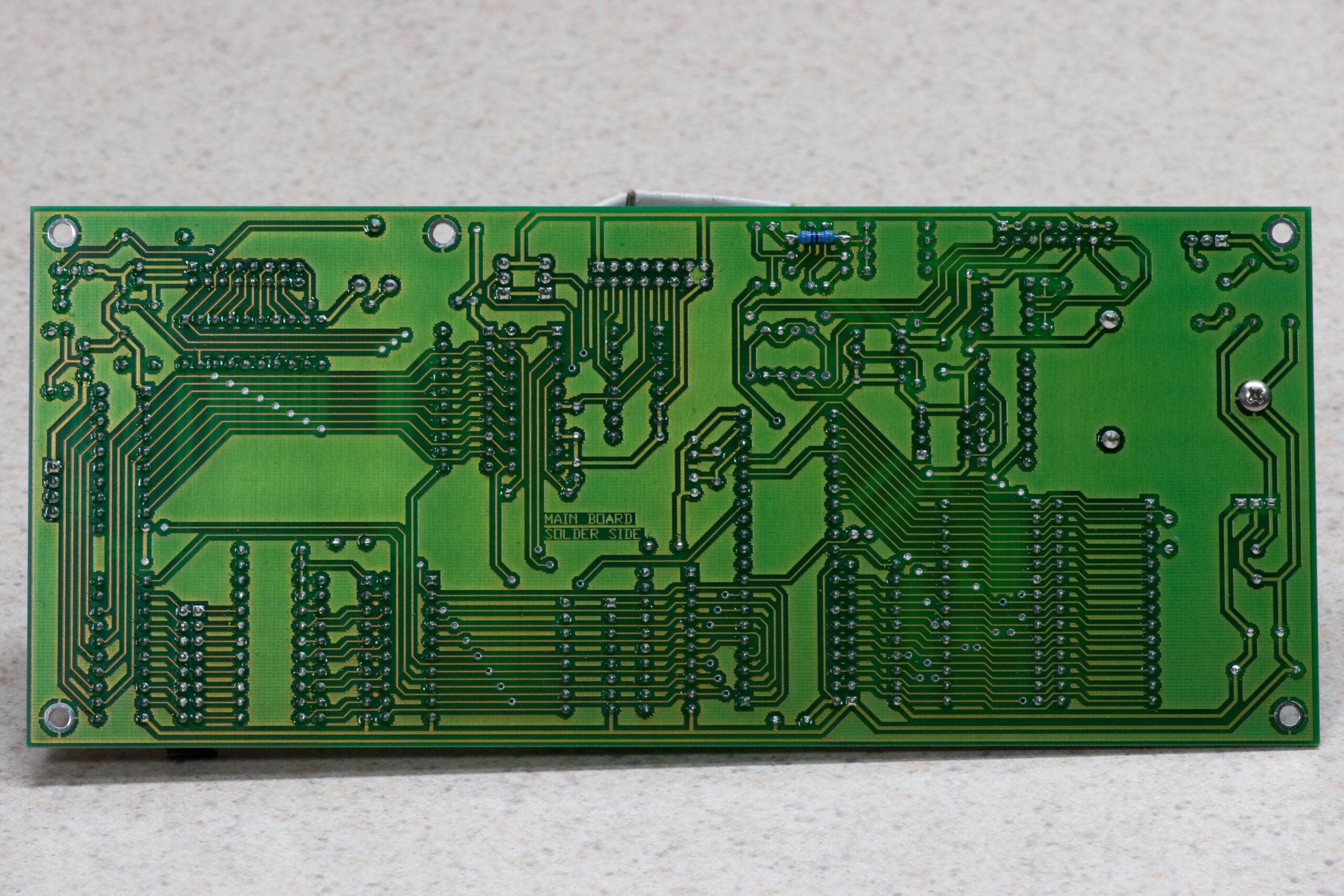
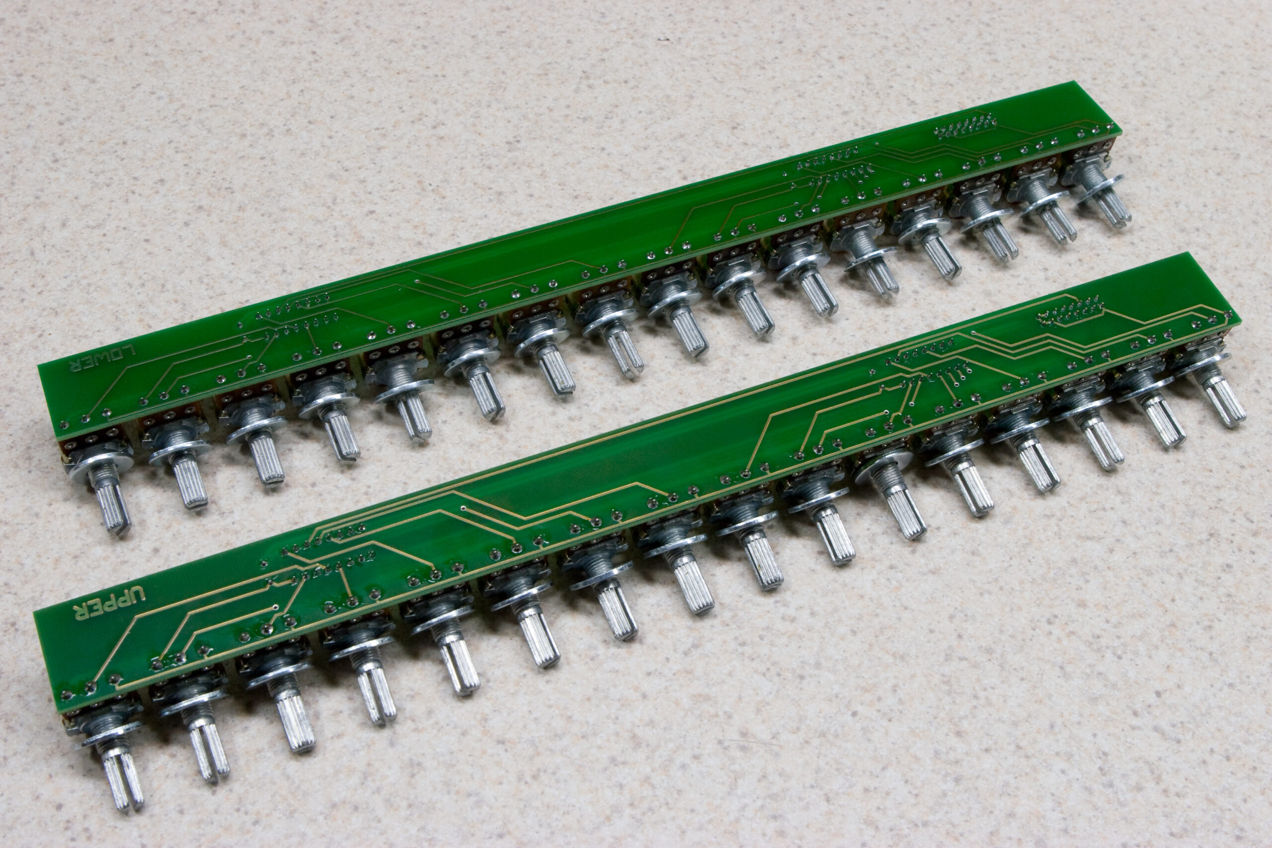
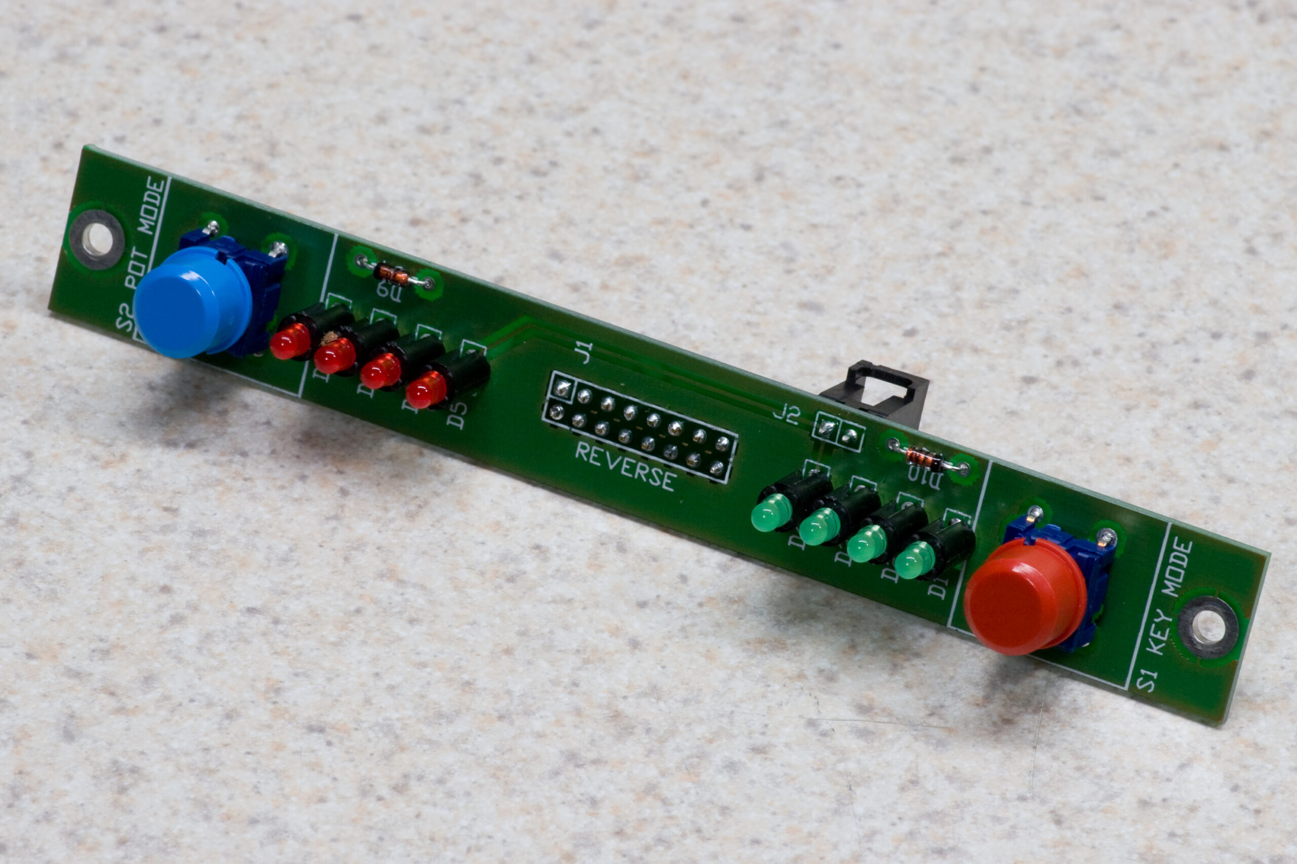
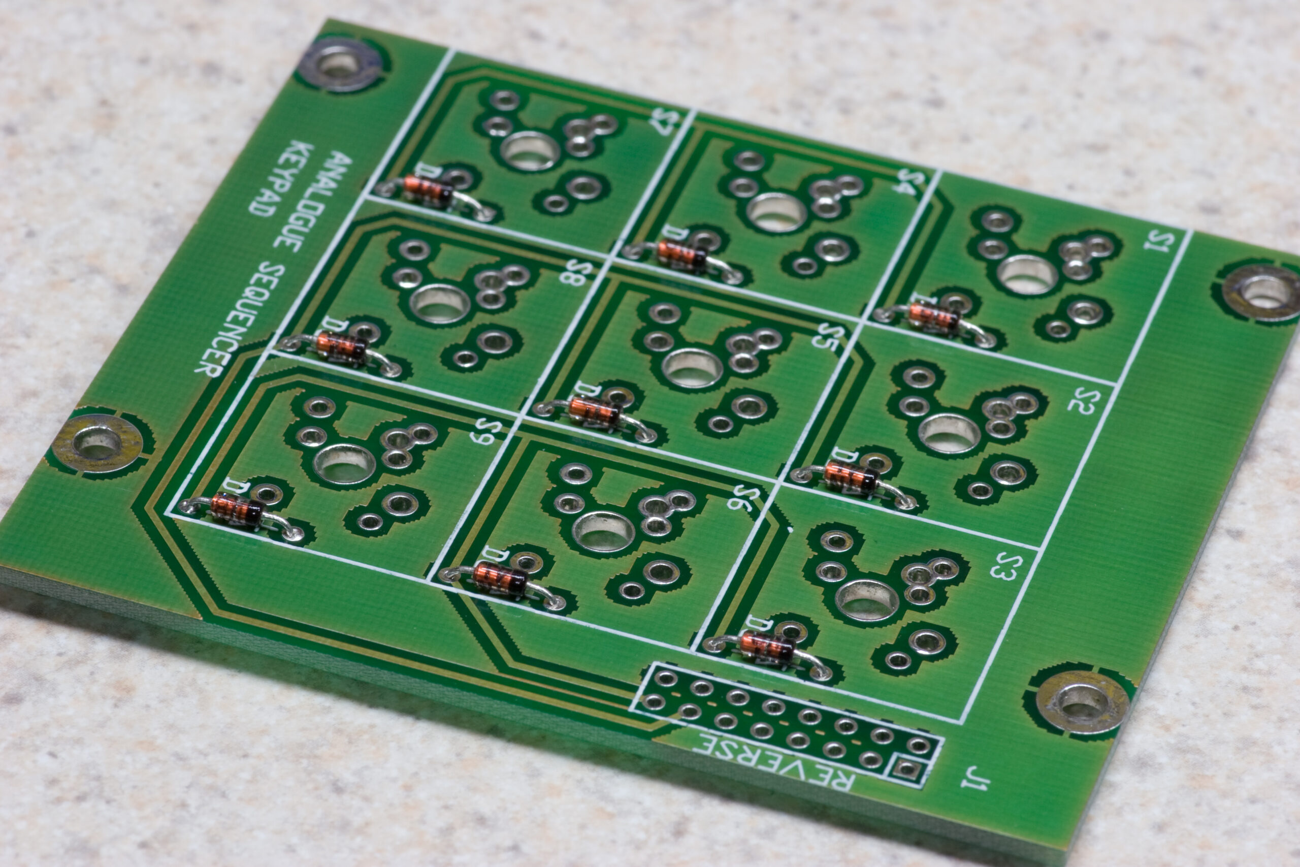
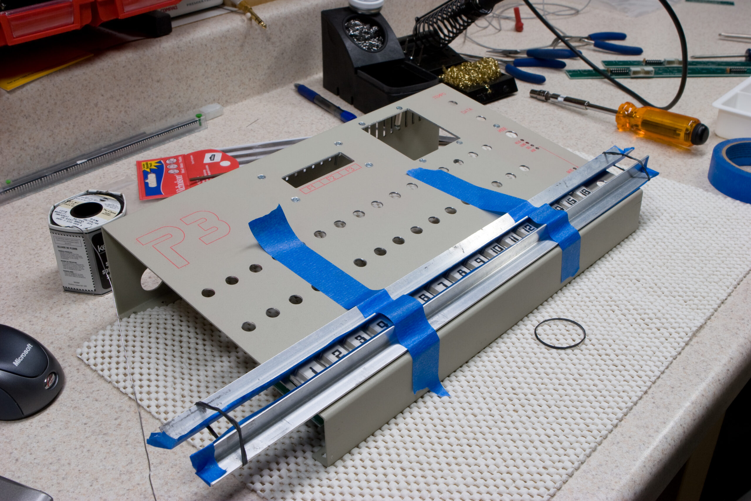
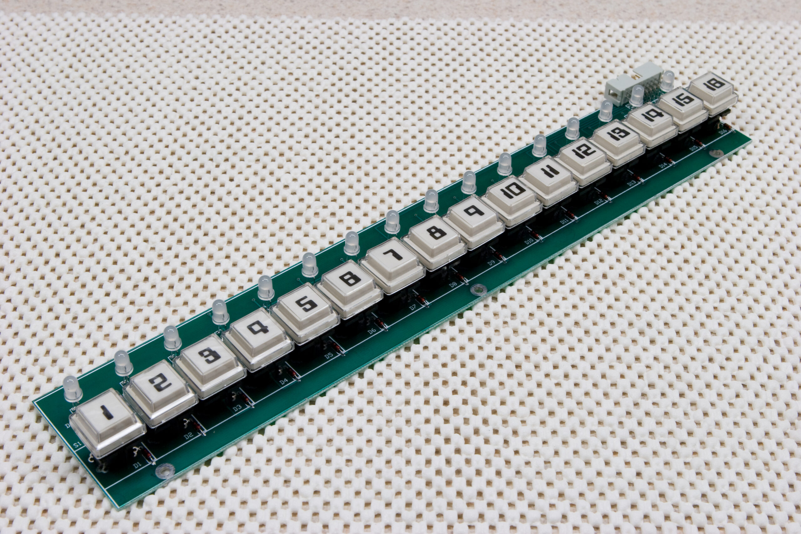
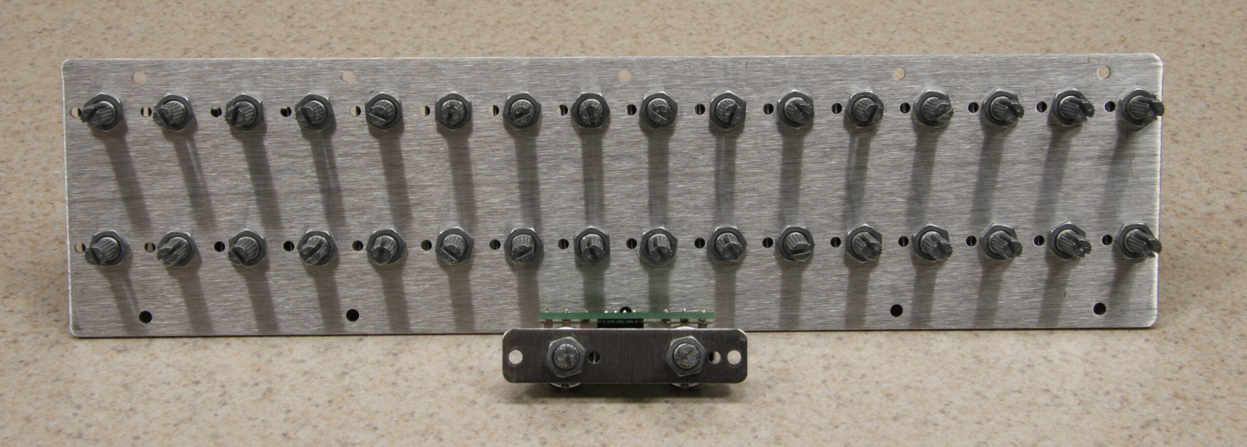
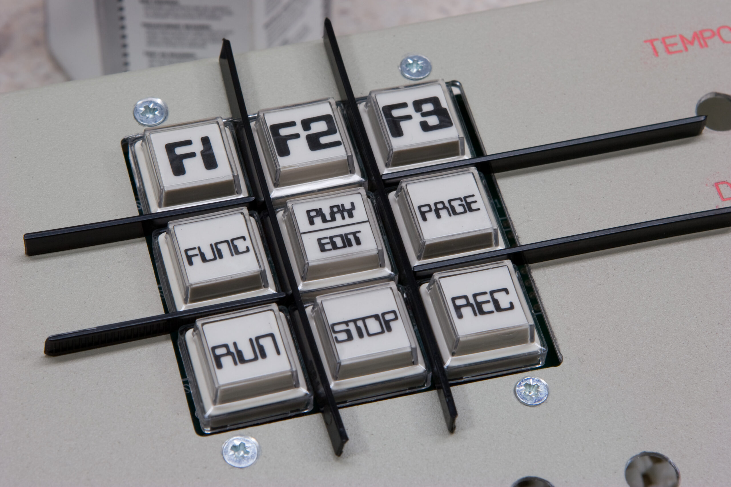
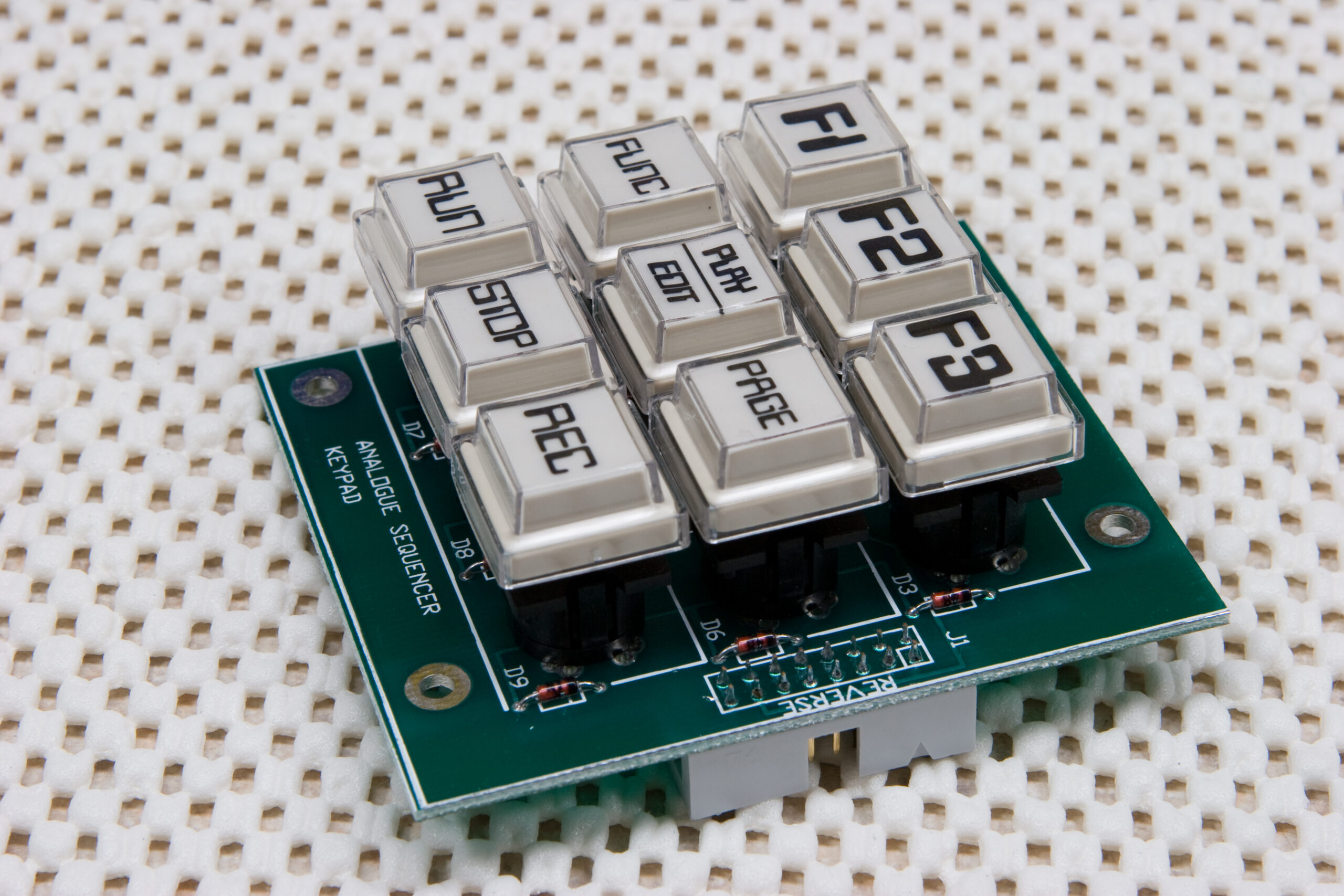
Beyond those three problems, the build is going quite well. I’m very happy with how both the step board and keypad came out. The IDC ribbon cables, their connection, and power input stuff also worked out great.
I was also able to get the latest bootloader and v3 firmware on the P3, which means that as soon as the other issues are sorted out I can get the MemX and latest v4 beta installed. After that it’ll just be time to install the knobs, test it out, and ship it back to Ivan.