So, after a week I had to revise this post substantially. Originally it was talking about how the bogons list contains private addresses and how in OPNSense this caused problems with using a private network ranged router (like the aforementioned GL-MT3000) as a WAN link caused problems. But then on a quiet Saturday morning a week later I went to reproduce the problem, gather data, and fix it, and… I can’t. So I’m just going to chalk that situation up to me being tired/stressed due to the lengthy power failure or maybe something getting weird/munged/misaligned rule-wise and a tidy-up sorting it out.
I don’t like it, but that happens sometimes. (Get something wrong, go to reproduce, doesn’t work…) What annoys me is went back and forth so many times when it happened that thought I had it right.
But, at least it’s working now, with nothing to fix.
Anyway, here’s the revised post without the now-known-false claims:
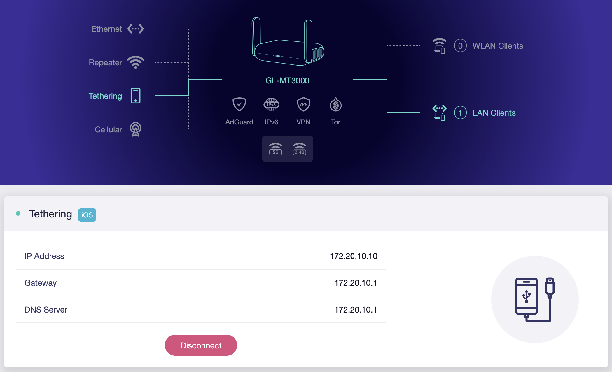
After a severe round of early September storms here in Southeast Michigan we’re in the midst of a multi-day power-and-internet outage. While mobile hot spots were kinda working, it was also a pain not having the normal network up, especially as I troubleshot why some Home Assistant devices didn’t come back online. So I set out to up our normal network with a tethered mobile phone as its public internet link instead of the cable modem.
This was super-easy to do, in general, using the aforementioned GL-MT3000 reset to defaults†, connected to an iPhone, in basic router mode, and plugged into the WAN port of my OPNsense router (replacing the cable modem). I did this instead of connecting the iPhone directly because OPNsense doesn’t have all the drivers needed loaded by default — changes I didn’t want to make for a temporary solution — and the router is down in the basement where cell phone signal isn’t quite as good.
While I considered setting up multi-WAN with failover mode, this is a really rare occurrence, and I won’t be keeping the phone connected after Wide Open West comes back online, so replacing the cable modem was much cleaner and simpler.
† Thanks to the lovely brownout, my GL-MT3000 would no longer boot. I had to use the Debrick via Uboot process to get it working again. Fortunately it wasn’t actually-dead. And now I’ll have to put back the IPv6 tunnel stuff… But at least that’s documented.
Chip, laying on Kristen’s lap, in the living room.
A couple years after putting together the HDMI-CEC to Onkyo RI Bridge I decided to give it a bit of an update and subtle name change. There were a couple problems that I wanted to fix:
Occasionally, usually in the middle of the night, the Home Assistant automation keying off of the Apple TV waking up would turn on the lights in the living room. The Apple TV seemed to wake a little bit for a firmware check, and a false positive in my HDMI-CEC watcher would trigger on this, turning on the lights and receiver.
Onkyo receivers also send data out the RI port, but I hadn’t tested receiving data from a device.
The name was also changed from “HDMI-CEC to Onkyo RI” to “HDMI-CEC and Onkyo RI” to better reflect that this bridges these two separate things into Home Assistant (HA). Originally I had the device itself turning the receiver on (via RI) after hearing a certain CEC command (no HA needed), but for flexibility I moved this logic into HA. The name change reflects that it doesn’t do the bridging itself and is really two separate functions that just happen to run on the same ESPHome device.
To handle this I broke it down into a few pieces:
Fix/update/resubmit the Onkyo RI support in ESPHome.
Refine what HDMI-CEC commands are considered to be the Apple TV waking up.
Rewrite/improve the ESPHome YAML.
Update Home Assistant (HA) to use these new features.
Again, leaning hard on an AI coding assistant† I started with building an HDMI-CEC sniffer in ESPHome, collecting a few days of traffic on the CEC bus, and built a good understanding of what the communication actually looks like.
The HDMI-CEC sniffer is here: sniffer.yaml (Note: Completely AI generated test code.)
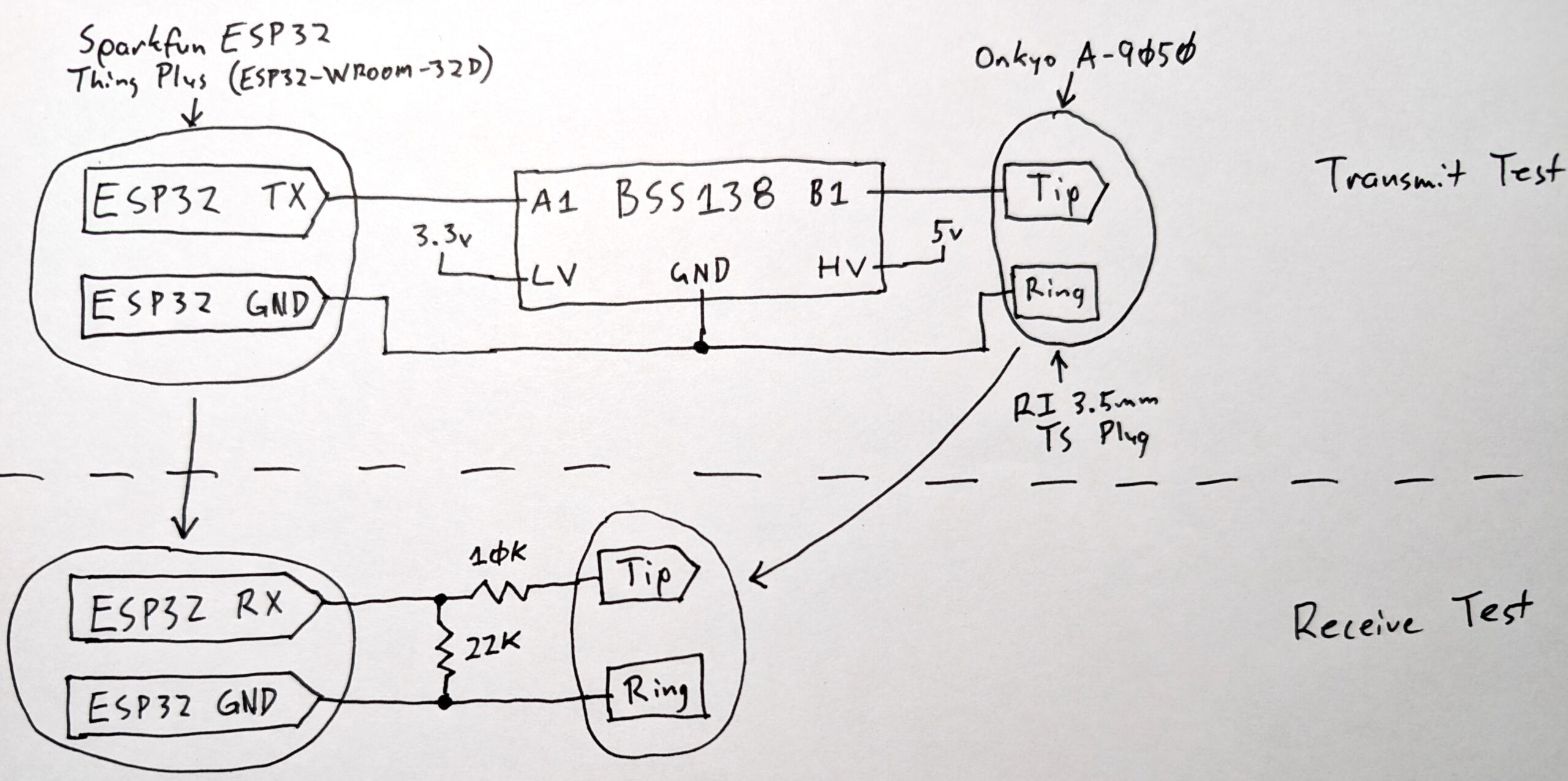
Next I worked with the agent to modernize my previous ESPHome Onkyo RI code for the current version of the platform, tested it in send and receive configurations, and submitted a new PR (#18585). This PR is much more robust than the last one, even including a hand-drawn schematic showing my hardware test setup. I intentionally did this using AI as a programming partner, leaning on it for code logic and consistency and testing, but doing the architecting and validation and and git/GitHub stuff by hand.
Test Transmit and Receive hardware for Onkyo RI integration in ESPHome.
Along the way I took a detour to inspect all commands that came out of the RI port when pressing the buttons on the RC-830S remote that came with the A-9050 receiver. Unfortunately, what I realized is that RI is more complicated than just a remote control command. I thought the RI port might re-transmit what the remote sends, but I was very wrong.
As (in hindsight is obvious), RI is an inter-device protocol for managing a home theater system. The remote is meant to talk to individual device. Supported (in function and expectation) by the RI mode switches in the back, parts of the remote might only trigger RI signals when certain inputs are selected, inputs might vary (or not cause) RI output, or surprisingly some buttons don’t cause anything to be sent. Or others work the same all the time.
Having set out to only update my current hardware to work better, I opted to not add any read-RI-into-HA stuff for now. There’d be a lot of complexity to unwind before it’d be usable, and I don’t have good use for it, so I dropped the idea. But at least the software support is there and tested.
(You can download the Onkyo RI transmit and receive tests for ESPHome here: ri-transmit-test.yaml / ri-receive-test.yaml. Disclaimer: These are both completely AI generated development test harnesses.)
With these two pieces — new understanding of HDMI-CEC and a freshened-up Onkyo RI component — I was then able to build a new config for the Seeed Studio XIAO ESP32S3-based hardware I already have in place. And along the way a previous bug I’d encountered with Over-The-Air (OTA) updates to ESPHome failing on this module got fixed, which is a nice side effect. Now it’ll be much easier to try out changes.
I’m pretty happy with this. The result is an expanded/modernized device that nicely communicates with modern (HDMI-CEC) and old (Onkyo RI serial port) home entertainment stuff, logically coupled together with ESPHome and Home Assistant. There’s modern code for RI in HA, and while the PR is still waiting to be merged, I’m hopeful. Going off the test results and AI feedback on the code quality I’m much more hopeful this time.
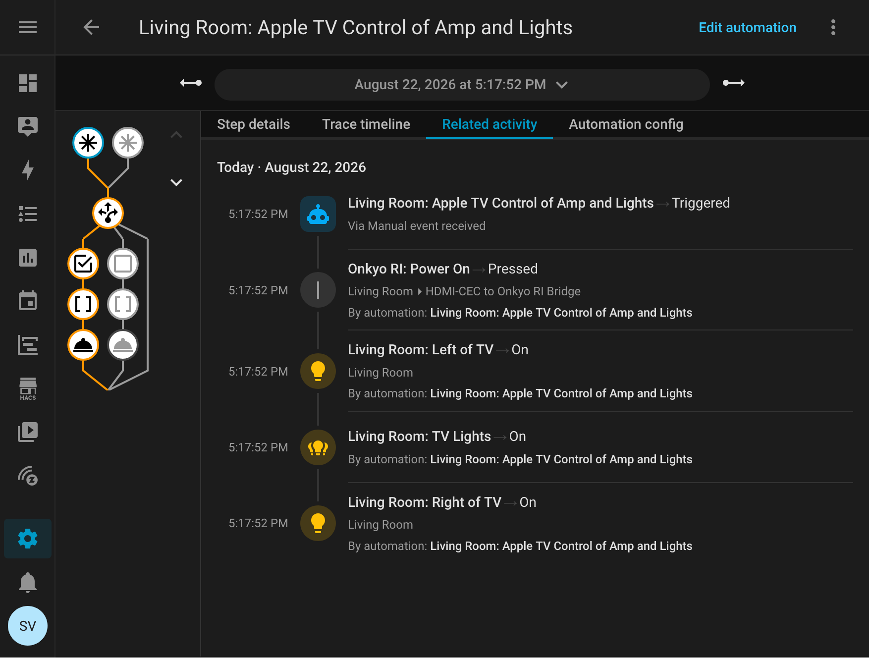
Home Assistant turning on the Onkyo RI receiver and living room light grouping after receiving an HDMI-CEC event.
Currently the typical usage flow is:
Push button on Apple TV to wake it.
Apple TV wakes Vizio TV.
ESPHome sees this happen via HDMI-CEC and informs Home Assistant.
Home Assistant turns on the receiver via Onkyo RI and some lights.
Then later, when the Apple TV goes to sleep (automatic or manual), ESPHome sees this, notifies HA, and an inverse flow happens.
In the future I might begin looking at waking or sleeping the system remotely by sending HDMI-CEC commands. This eluded me before, but with some automated analysis of traffic on the CEC bus, I might be able to make it happen. Maybe it’d be nice to have the system wake up remotely, perhaps as part of a lets-watch-TV automation? Even if I don’t do this in the end, it would at least be nice to know how…
I might also look at ingesting commands sent out by RI, but this goes beyond the receive-only test and will both require new hardware on the ESP32 side (to handle send and receive on the same pair of wires) and digging into the RI complexity, so… probably less likely.
Using This in Home Assistant
With the HDMI-CEC triggers for the logic being in Home Assistant, and as part of handling the random wakes (receiver/lights turning on), I needed tighter triggers in Home Assistant. Here’s what’s now used used, specific CEC frames:
Specifically, this looks for CEC frames that are from source 4 (the Apple TV, a playback device).
The system_on event is the Active Source opcode (82), from physical address 5.0.0.0 (50:00) or the Apple TV’s HDMI port. Or, otherwise stated, a playback device set itself as the active source of content, and is connected to port 5.
The system_off event is the Report Power Status opcode (90), with Standby power status (01): the same playback device went into standby.
This works for my setup, but be aware that it might not work for you.
With things plugged in differently, or possibly with different devices, different addresses are likely needed. For example, if I added another playback device and added it the source could change. If plugged into a different port, the physical address (payload) of the Apple TV would change from 5.0.0.0.
To use this yourself you’ll want to inspect the HDMI-CEC frames (look at turning logger level: to DEBUG) and using esphome logs) to see what’s on your bus before writing the automation. LLMs (AI) are really good at helping with this kind of protocol analysis.
† Claude Opus 5. Even though it’s the results that matter, part of me still feels compelled to mention every time I use AI tools to develop something. Yet I don’t mention using search engines, IDEs, compilers, etc… And yes, this entire blog post, comments in the main ESPHome YAML, and the PR was written by hand, just by me.
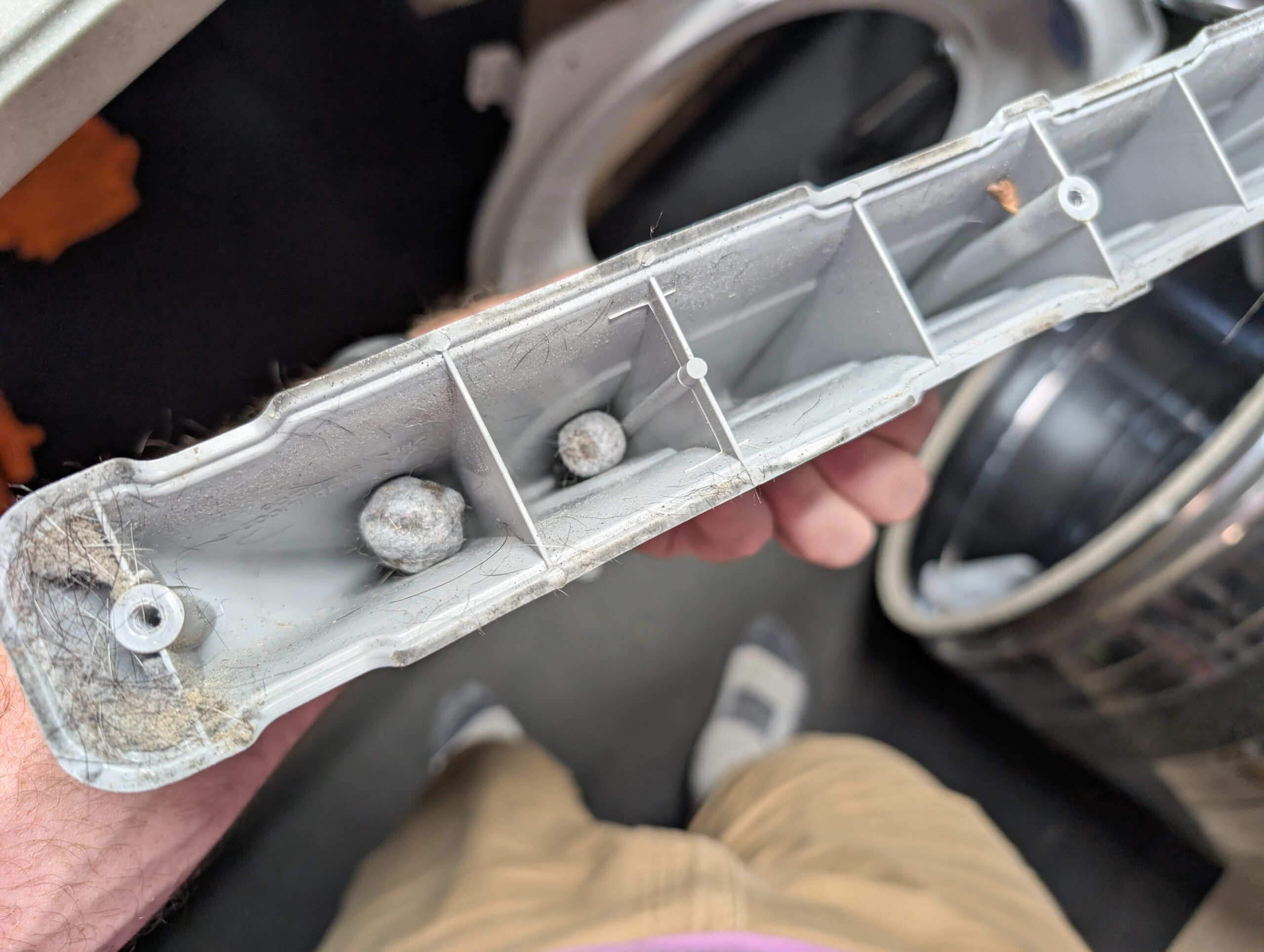
Balls of lint and (dog?) hair that developed inside the plastic paddles in our dryer.
A few days ago our dryer began making some new rattling noises when running, so I took it apart to clean and repair† it. In the process I removed the plastic paddles from the inside of the drum, as I’d previously bobby pins stuck behind them, so I figured I’d clean them out as well.
Pellets where they formed inside the dryer drum paddles.
Inside of most compartments of the paddles were these gumball-sized formed pellets of lint and hair; a sort-of felted pom-poms. I find them fascinating — and a little bit gross — as they slowly built up over time from what’s otherwise just dust. (I imagine there’s some fabric softener and skin oil in there as well, functioning a binder to help hold it all together.)
I can’t help but be reminded of “Stan’s Boogers” or “Stanimals” that build up inside of some tubeless bicycle tires as the solids in the sealant come out of suspension, stick together, and tumble around. But instead of being latex lumps they are people and clothing residue that’s been building up since the dryer was bought, before we owned the house, back in… 2015 or so (if I remember the date stamp correctly).
† The dryer needed a new set of rollers, as the ones I installed in early 2023 had already begun binding, causing the drum to skip and vibrate while turning. I also replaced the belt for good measure, since that wasn’t done before. Thankfully a whole roller + belt + idler arm/pulley kit can be purchased via Amazon for ~$34, shipped overnight. The repair is overall easy, it just takes a couple hours disassemble the dryer, vacuum it all out, and put it back together.
I previously had replaced only the rollers, greasing the axles with a provided white lithium grease. This time the kit came with new axles as well, so I replaced the entire assemblies, lubricating the roller bushings and axles with Dri Slide Bike Aid, a super-nice molybdenum disulfide (“moly”) dry lubricant (after the carrier evaporates). This both made the wheels spin super-smooth and should resist collecting dust/lint/hair and hopefully make the new set of rollers last longer.
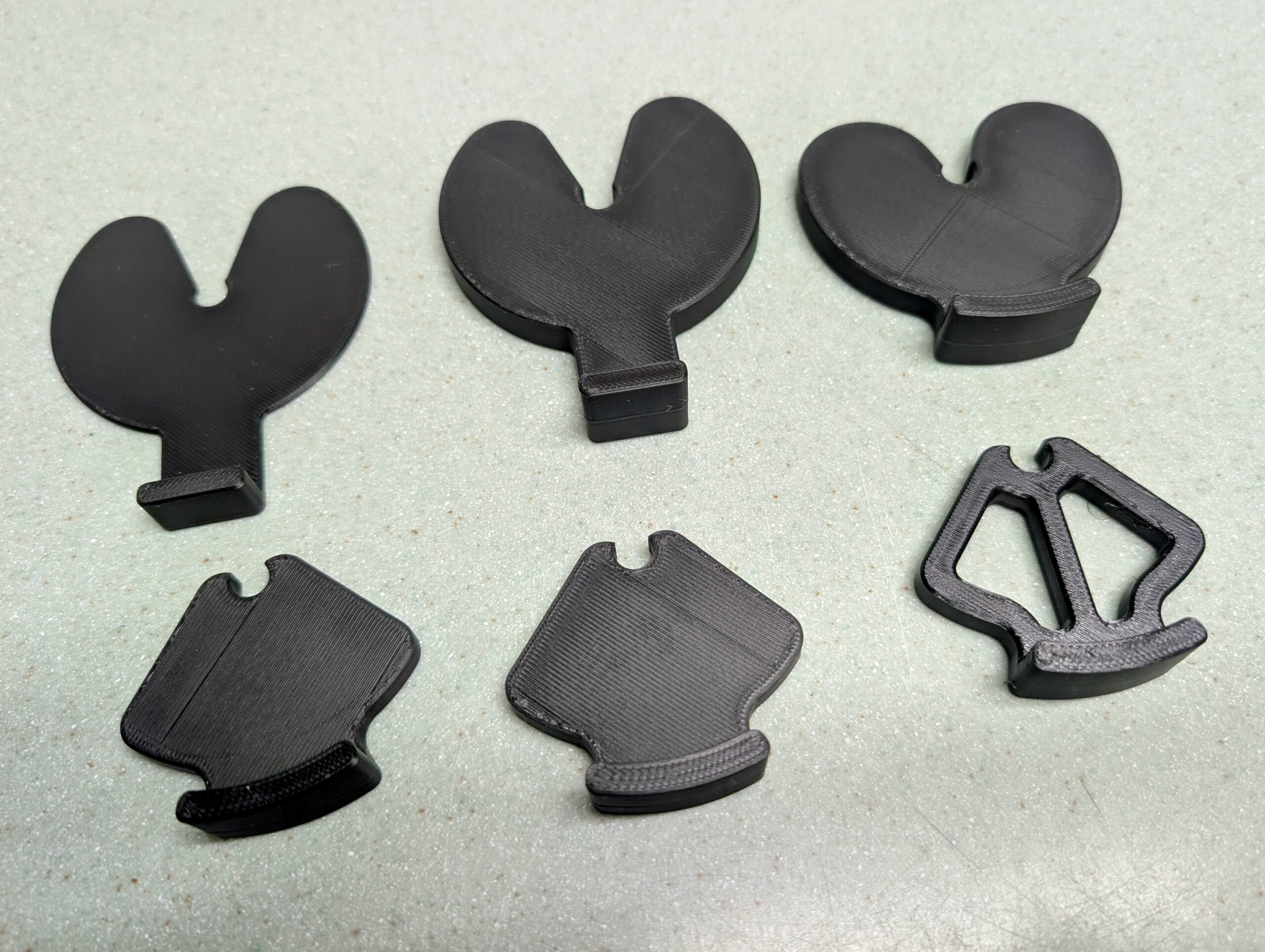
Six iterations, from initial to final, of slip-fit stove knob lockouts.
Even for a few-hour project, I find it interesting to look back at the various iterations of developing something. In this case it’s six different versions of a slip-fit shim that latches on to our stove’s knob shafts, preventing them from being pressed in turning the gas on or igniting. Kristen wanted these to help avoid accidental knob turns (from people, dogs, etc) and being stuck inside by extremely poor quality air from wildfires, it was today’s after-work pass-time.
I’m happy with where the idea ended up. My original idea was for something that pushed in from the bottom and clipped in place, but because of the D shaped knob shaft I ended up with something that’s slipped in horizontally, and as it falls/is turned to a natural position with the tab down, it sticks in place. Along the way I screwed up the thickness, tried making things smaller, then smaller still, then had to nudge the thickness, and then finally cut out a bunch of the inside to use less plastic.
The first five were prototyped in PLA, and for the final items I printed them in PETG. Although I think the plastic might have been a bit damp as it was stringy… Still, it was easy enough to clean up and fine for this.
The models can be found here on Printables, if you’re interested. Or I’ve got a simple demonstration video of it here.
In our HA instance I have two helpers, each called Interior Lights, with one being a group of switches and the other a group of lights; both containing only things we’d consider interior lights. I then have an automation that turns both groups off, and trigger it from something like All Interior Lights Off which I’ll commonly trigger before going to bed, when leaving the house, etc.
Because a group entity can only hold the same type of entity, and we have lights that are both lights entities (i.e. bulbs) and switches entities (i.e. smart switches controlling dumb bulbs) we need one group for each type.
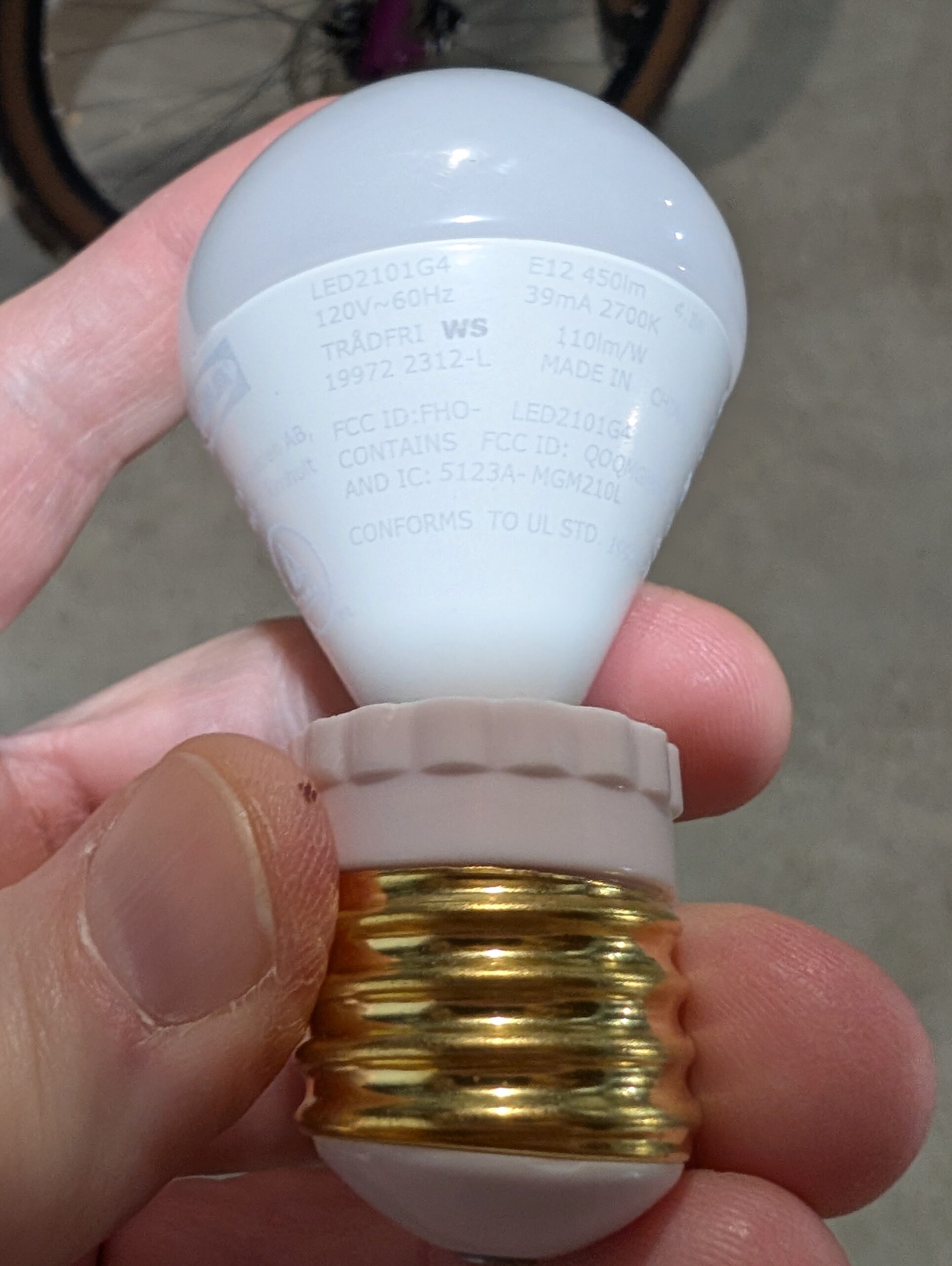
The specific problem was that two lights in the group — one being an IKEA TRADFRI 800 lumen bulb and the other BTF-LIGHTING Zigbee single-color LED controller — started acting oddly. At first it was hard to tell what was going on, the IKEA bulb would seem to be on when not expected and the LED strip would be off when it should be on. Eventually I found repeatable cases:
When triggering All Interior Lights Off automation, if the IKEA bulb was already off, it’d turn on at minimum brightness.
After using All Interior Lights Off, the BTF-LIGHTING LEDs, on next on command, would flicker on and then almost immediately turn off.
It turns out the problem was having transition: 0 on the light group’s off automation. Back when doing tweaking for the Hue bulbs I changed this because otherwise these bulbs would dim out over 1-2 seconds instead of just turning off, and I didn’t like this. Unfortunately, this change exposed some bugs.
So I removed the transition from the automation and poof; no more weird problems.
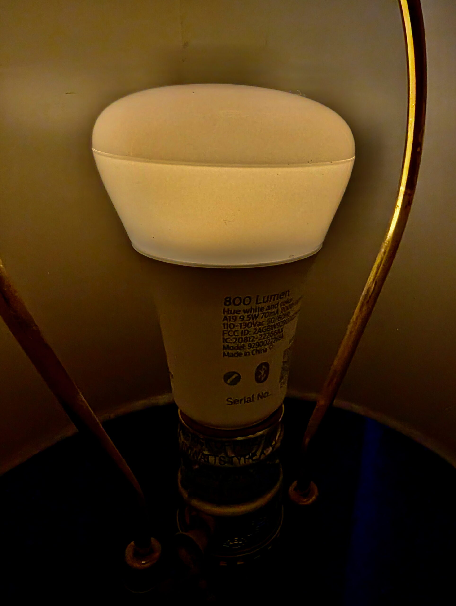
In continuing to optimize things I wanted a bulb that has an even-dimmer and warmer initial brightness than the IKEA TRADFRI LED2101G4 (in an E26 to E12 adapter) I’ve been using. I’ve now settled on Philips Hue White and Ambience 60W A19, as it’s both lower brightness and warmer at initial turn-on and has a brighter high end, making it more usable when working on things around the bedroom.
With the Lighten Up! I had used a halogen bulb, which combined with the dimmer, made the initial brightness so low the filament was barely visible with the naked eye. This made the initial-on not noticeable and didn’t jar me awake. To try and replicate something similar I considered the Shelly Dimmer 2 and putting a halogen bulb back in place, but I wasn’t really wanting to go back to bulbs that give off so much heat and use so much power. And while I find Shelly devices well engineered, I wasn’t very interested in more WiFi IoT devices. (I really prefer Zigbee or Z-Wave for security reasons.)
Thanks to this /r/homeassistant thread I was prompted to try some Hue bulbs, so $76.31 to Amazon later and I had a pair. They easily adopted directly into HA and after a little tweaking (mostly adjusting automations for the new devices), I’m happy with them. The warm/low setting is really quiet dim and yellow-reddish, and at full brightness it’s… nicely bright.
I may tweak the curve used for bringing the brightness up, but thankfully the script I use (Ashley’s Light Fader 2.01) has a whole range of curves available. I’m currently using the default easeInSine, but this morning it seemed to hit the final brightness a bit abruptly, so I may try something like easeInOutSine.
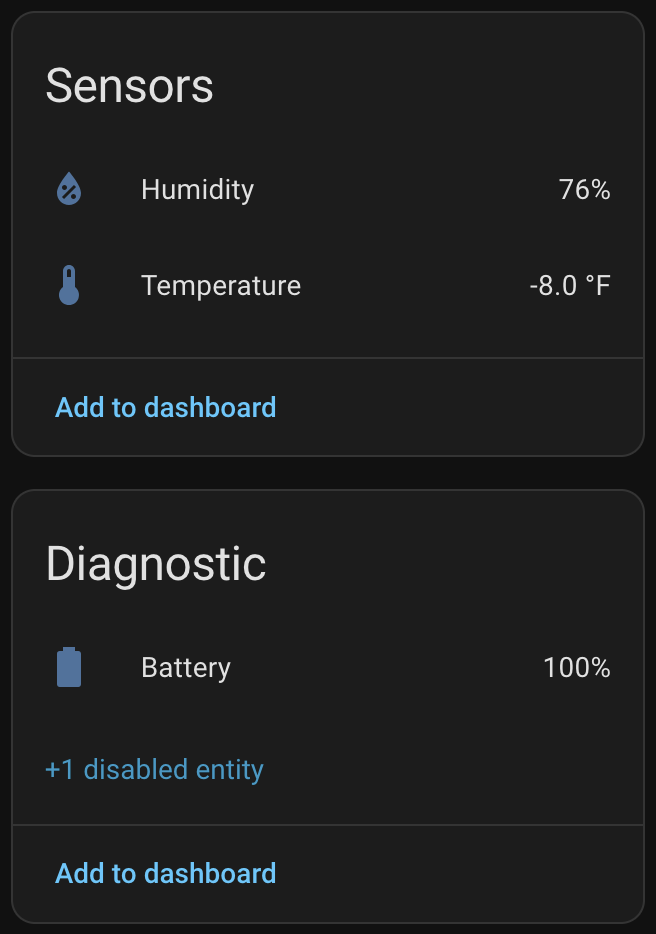
SwitchBot sensor showing well-below-0°F reading and still 100% battery after a month of winter.
At ~US$31 for a three pack (via Amazon) they are 1/3 the price of the ZSE44, take AAA batteries, and are IP65 rated. The specs also claim they work down to -40°C (-40°F) with Lithium batteries. Basically perfect for outdoor spaces including attics, crawl spaces, etc.
I installed this side by side with the ZSE44 with the solar radiation shield on the back fence, and as hoped, it’s reading well below zero and working fine. I also put the other two (from the three pack) in the fridge and freezer to see how they’d do there, and while the freezer doesn’t get as cold as it currently is outside, it was a good preview of data before the temperatures dropped. And all three currently are at 100% battery.
Now that we’ve had our first well below 0°F temperatures of the season I can say that yes, the SwitchBot sensor is working properly, with more frequent updates.
When initially setting up Home Assistant its purpose was to log temperature and humidity at various points around the house. I started with the cheapest sensors available at the time — Aquara Temperature and Humidity Sensor — but after a couple years have passed I’m finding these a bit disappointing. The CR2032 battery life isn’t great (even indoors they last about 8 months), and I’ve had a few of them just die. While they are small, the size benefits don’t outweigh the battery and longevity hassles. The Zigbee connectivity is pretty simple and mostly works, but when the battery or device dies it just kinda… falls off the network and works/rejoins (even after a battery swap) unreliably. I think I’ve disposed of three in the last year.
The biggest downside to these SwitchBot sensors is they use Bluetooth Low Energy (BTLE) for communication. This does not have nearly the range of Z-Wave, which was my original reason for putting the ZSE44 in the back yard.
Thankfully Home Assistant can use Bluetooth Proxies (networked remote BT sensors), and the Shelly 1 — a UL-listed WiFi-controlled smart relay — is one. I already had a few of these around the house to control lights fixtures, so via the proxies I’m able to get enough BTLE coverage to pick up the sensor along the back fence and the ones in the fridge. It’s no Zigbee or Z-Wave or Thread-like self-healing mesh, but so far it’s working well. And really, with the devices’ fixed locations, there’s not a ton of practical difference between setting up a mesh network with well-planned routers (Zigbee) or repeaters (Z-Wave) and deploying BTLE proxies.
I’ve also picked up two of the SwitchBot Meter Plus devices which is a temperature/humidity sensor with an LCD display that runs off of two AAA batteries. It’s not as robust as the Indoor/Outdoor sensors, but is perfect for somewhere I want to see the local temperature visually and log it in Home Assistant; indoor uses. In years past I’d place temperature/humidity displays like this around the house so I could see some data, and these are basically the same, except with logging to Home Assistant.
Long-term, as they fail, I could see myself replacing the remaining Aquara sensors around the house with these. Even the couple of ZSE44 sensors I have may get replaced with these (particularly the one in the back yard). But, for now, I’m just glad to know how far below 0° it really is, and have record of this, because data is nifty.
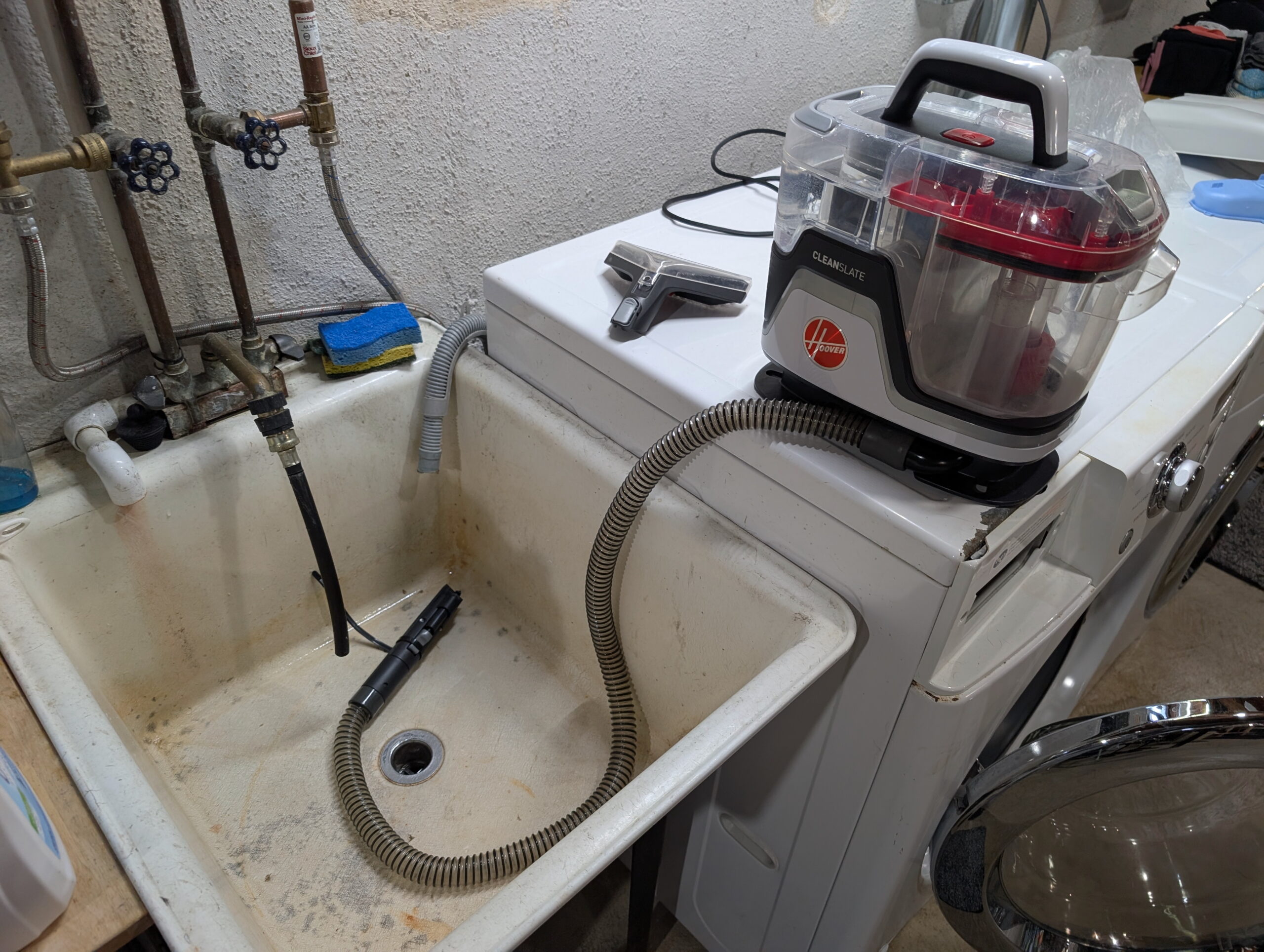
Hoover CleanSlate sprayer being primed after it’d dried out.
We have a Hoover CleanSlate portable vacuum thing and it’s incredibly useful for cleaning up small spills / stains / cat vomit / etc. This morning when I wanted to use it the sprayer was no longer working.
It had worked last time, and I’m judicious about letting it dry out between uses (because I don’t like mold), and it turned out this dried out the pump which in turn meant it needed some time to self-prime before it’d spray.
The solution was simple: put a releasable cable tie around the sprayer handle, put that in the laundry tub, and let the unit run for a few minutes. After this it was spraying fine and all was good. (Yes, you could hold down the trigger, but I’m lazy. And I wanted to make a cup of tea.)
(This is part of my neo-Luddite series where I document things in writing. Because I find a watching a multi-minute YouTube video to access info that can be acquired via a few paragraphs of text to be maddening.)
Solar radiation (sun) shield mounted to the chain link fence.
I have temperature/humidity sensors in the back yard, both for Home Assistant and a La Crosse “atomic clock” on the wall of my office. These had been mounted nicely in the shade on a north-facing post on our old wooden fence, but after the fence was replaced I needed to find somewhere else to put them. The first place I tried, the back side of a utility pole, was too close to the fence and they’d read overly-warm in the evenings as the sun was hitting it. (And had the legal issues around mounting things on a utility pole.)
There are myriad different “solar radiation shields” available either for purchase or 3D printing, but they are generally designed to hold one sensor and be mounted on a pole, get held together with bolts, or just aren’t a great design.
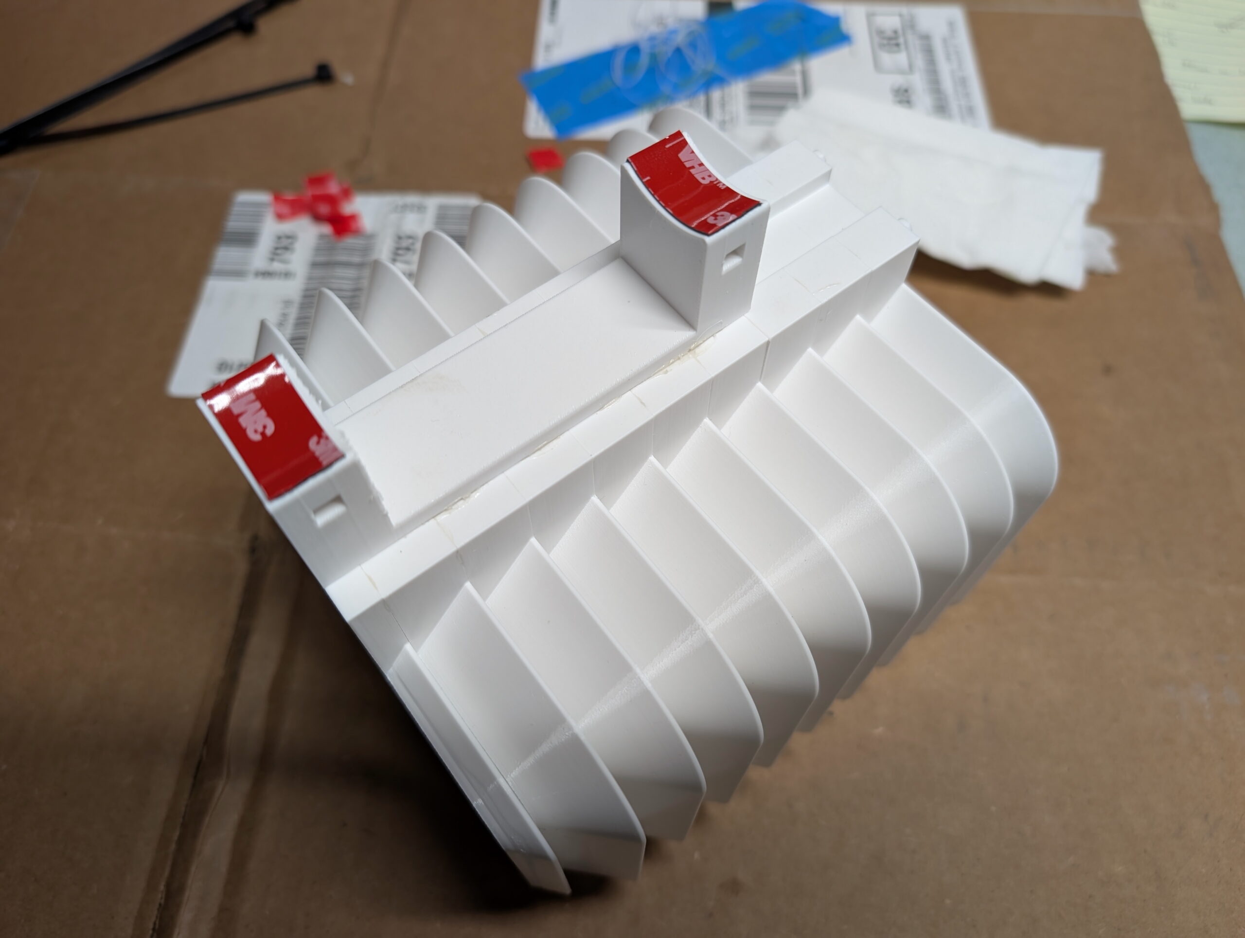
I’m really happy with how it came out. In the end it’s a simple two-piece (plus mount) design, with one being the roof and the other a body piece. Each body piece is 15mm tall so I printed off the requisite number to hold my sensors (nine), one roof, and stuck it all together with J-B Weld PlasticBonder epoxy. Pegs and holes align the pieces and make it easy to glue together.
The vents offer shade all the way to horizontal while still having massive openings, so I think it’ll work well. The roof is a bit more translucent than I cared for, but by lining it with some foil tape it’s now nicely opaque. I’m not concerned about the transparency of the vent slots, but may add tape later or re-print with a different filament if it seems to be a problem.
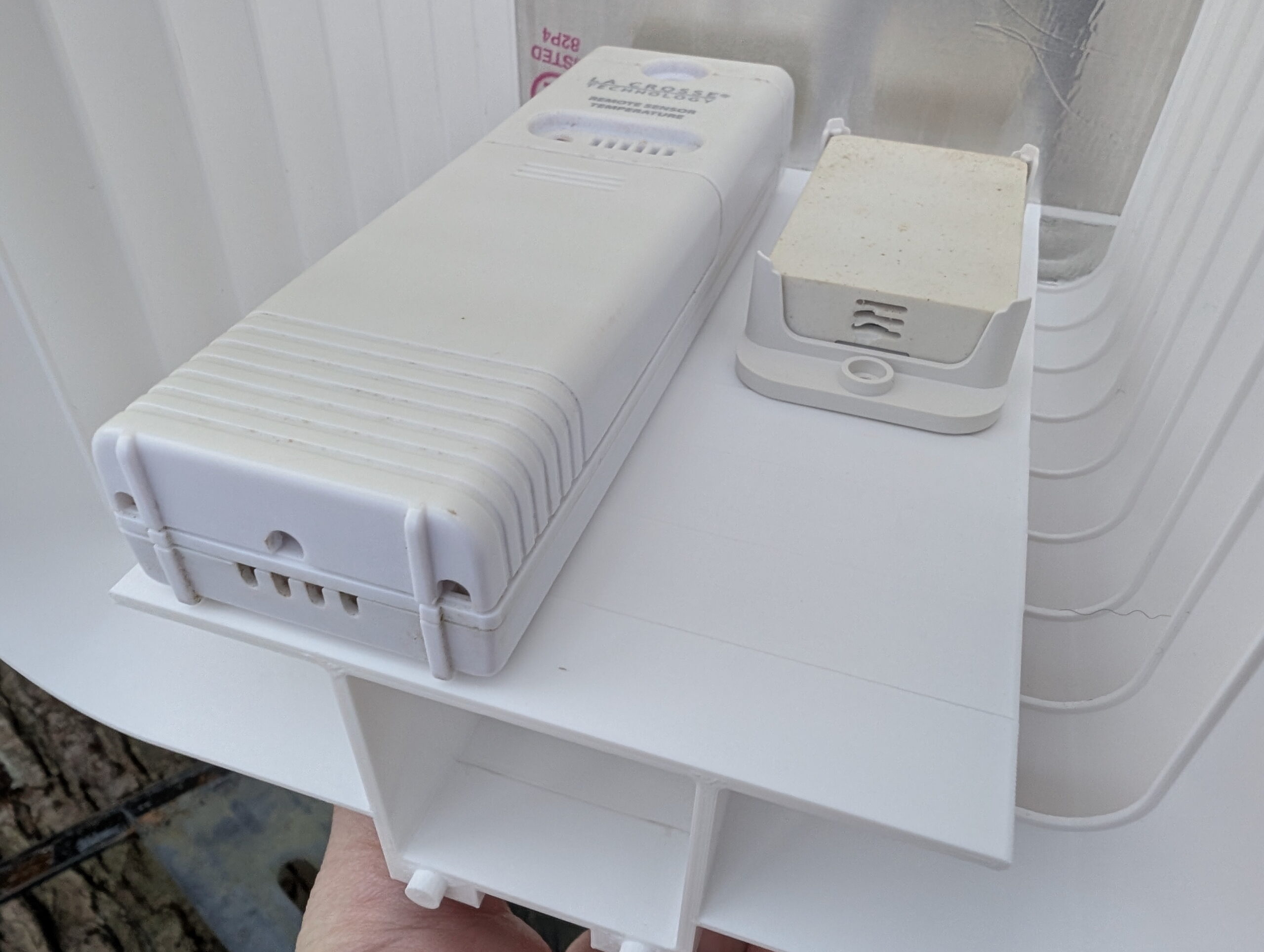
Currently I have La Crosse TX141-BV4 and ZOOZ ZSE44 sensors installed, but may add others as I want to replace the ZSE44 with something that reads negative values. The sensors are held in place using 3M VHB 4910, which is easy to remove (by sawing through with dental floss then rolling off with a finger) but otherwise holds very firmly, especially against shear loads. It’s also thick enough to fit between the ribs on the back of the ZSE44 mount. And I had it on hand.
Chain link fence post mount, with VHB 5925 for additional support.
I initially designed this to use QUEEN SIZE BrickClip fasteners and hang it off the north-facing side of the chimney. Due to the weight of the assembled unit with sensors (~350g) and wanting to keep it away from the house’s thermal mass, I designed a chain link fence post mount. This allowed me to place it quite close to where the sensors previously had been, a nicely shaded yet breezy location. The designed-in slot (originally for BrickClips) just happened to allow easy addition of other mounts.
The entire unit was attached to a chain link fence post using black UV-resistant cable ties and with 3M VHB 5925 tape for a bit of additional stability. This tape works well but also was chosen because I had it on hand and it’s nice and thin. While this is a strong adhesive it’s really only needed for a bit of friction to keep the mount from twisting on the pole if bumped.
So how does this one differ from the other designs I came across? Or, differently stated, why did I bother making my own?
Sensor-Agnostic: Flat platform allows any sensor to be stuck in place. Most designs are for a single sensor type.
Larger: Most other designs only hold one sensor. I wanted to hold two or three.
No hardware: Many other designs are held together with bolts. I’m fine with gluing it together as this makes everything else simpler.
Flexible Mounting: A simple 15mm x 5mm notch in the back both allows BrickClip fasteners to be used while also a simple platform for integrating other mounts (such as the chain link fence mount).
Full Body Support / No Arm: Many other mounts replicate the shield-on-an-arm design of commercial pole mounts. I am concerned about FDM printed thermoplastic sagging, so either this needed to be metal, or the support done differently. I also had no need for a pole mount.
I’ve been using, and liking the ZSE44 Temperature | Humidity XS Sensor, with one in the attic and another in the back yard. It seems to work well, has a long battery life, and works great at pretty-far distances. But today I ran into an interesting quirk: it will not report negative numbers.
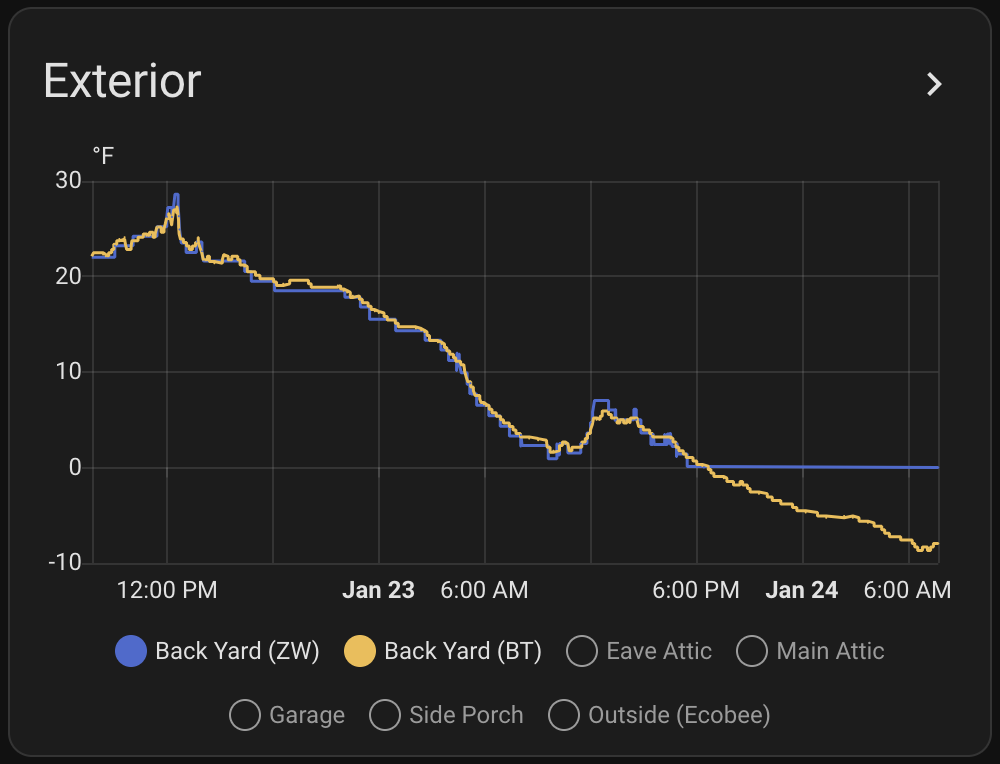
We’ve had a hefty cold snap here in Southeast Michigan, and last night the lows were well below 0°F, but I noticed that Home Assistant (see screenshot above) flatlined at 0°F for the back yard temperature.
I ended up asking ZOOZ customer service about this, and I was told it’s not designed for freezing temperatures, and thus won’t report negative numbers. So even though it’s working well at quite-below freezing temps, has been for the last week, and is even working fine now at ~4°F (reporting strong battery and active communication), a firmware limitation keeps it from telling me the actual temperature.
So, regardless of whether you have it set to Celsius or Fahrenheit, 0° in that scale is the lowest it reports. If you are using one of these in Celsius mode, you can get a bit more range by setting it to Fahrenheit and converting the value, but it only goes so far. (And yes, I tested the inverse by switching the ZSE44 to Celsius mode and saw that Home Assistant wouldn’t show below the converted 32°F.)
I’m a little irritated by this, but as it’s rarely this cold here, and the sensor otherwise works fine, I’m not planning to replace it. It’d just be nice to know the actual temperature outside via this sensor. The technical specs say it only works for 40°F to 90°F, but with it in the shade on our back fence or in the attic I’ve seen accurate values well beyond that.
The ZSE44 uses a SHTC3 [link mine] digital humidity and temperature sensor. The sensor covers a humidity measurement range of 0 to 100% RH and temperature measurements range of -40 C to 125 C.
While emailing back and forth with ZOOZ support, and their support person claiming the limit is because of the components, and they aren’t open to changing the firmware because that’d put it outside of specs, I did some digging to validate their claims. It turns out:
So between the range for the sensor, the suggested batteries, and the Z-Wave chip, a range of -40°C to +60°C would be fully within spec for all components.
Thus, the currently stated limitation for the ZSE44 of 40°F to 90°F (~4°C to ~32°C) is radically narrower than what any of the individual components, including the Z-Wave chip and battery) are spec’d to operate at. And I’ve demonstrated that all the components work at a much wider range: typical lower Michigan weather.
This make me a bit more irked at the limitations of the firmware, but thankfully after a bit of email discussion this information was sent to their development team, so I’m hopeful they’ll recognize the disparity and correct things.
But for now, at least now I know what’s going on.
(I could probably go to a different temperature sensor type, but all the really wide range ones, such as are meant for monitoring chest freezers, aren’t Zigbee or Zwave, and I don’t really want to add another protocol to my Home Assistant setup… Maybe that’ll be a project for this summer. Maybe…)