Press "Enter" to skip to content

Category: electronics

Ivan’s P3 is Finally Done

Screenshot of MIDI-OX displaying sync data from Ivan's P3 sent via the SYNC port.

That right there is a screenshot of MIDI-OX displaying data coming into a MIDI port, including a START and STOP message. This wouldn’t be anything too special, except for that it’s coming out of the SYNC port of Ivan’s P3, which means that the MIDI Sync issue which I’d previously mentioned is now resolved.

It turns out the problem was related to some changes which Colin had made in order to eliminate unintended triggering of the PICs inputs. It appears that this new code was mostly a backport of the firmware for the v1.6 boards (these are v1.5) which included the function for DIN SYNC passthrough, but doesn’t seem to default to having MIDI sync on.

The solution is to boot the P3 while holding down the 1 key. It will then tell the PIC to flip into MIDI mode, the PIC will write 00 to the first byte of its EEPROM (so it always goes into MIDI mode in the future), and then as soon as it first receives a RUN command it’ll start spraying out the clock / start / stop commands seen above.

I guess if I had been better (or more thorough) at reading disassembled PIC code I could have seen it doing all of this, but I’m not really that familiar with it yet, and I didn’t want to spend six hours looking up opcodes I didn’t understand and what each register written to was. Ah well, at least it’s working and I know what happened. Now I just have to pack it up and get it back to Ivan.

Leave a Comment

Playing with the PIC12F629

Tonight I did some more digging into the problems I’ve been having getting the MIDI sync working in Ivan’s P3. I had been sent some new firmware to try, and while that (in the disassembler) appears to deal with the right pins (GP0 as output, GP5:GP4 as input), it didn’t work. Tonight I did a good bit more digging and eventually ended up writing this program as a test.

Based on my understanding of how the PIC in the P3 with v1.5 PCB works, this program does the following: GP0 is set to low, then whenever GP4 changes state GP0 is changed as well, but only if GP5 is high. The end result is that on the output pin of the PIC, which connects through to the SYNC output, I basically see a mirror of the inputted sync signal whenever the sequencer is running.

I don’t think that it would be a huge stretch to write my own version of the software that is supposed to be in this PIC, but I haven’t gone that far. As far as I’m aware all I’d need to do is have each sync pulse received cause a MIDI Clock message to be sent out of GP0, and whenever GP5 goes high or low send a respective MIDI Start or Stop. That said, this P3 should really be running its official software, not my replacement stuff.

Hopefully I’ll receive some new firmware for it soon, and hopefully that firmware will do what it needs to. If I’m bored enough tonight maybe I’ll try and follow the flow through the entire program in the disassembler and figure out where it’s going wrong.

Leave a Comment

P3 v1.5 MIDI Sync Issue

Looking inside of Ivan's P3 while the micro grabbers are connected to ground, sync in (to the PIC on GP4), and what should be MIDI out (from the PIC on GP0).

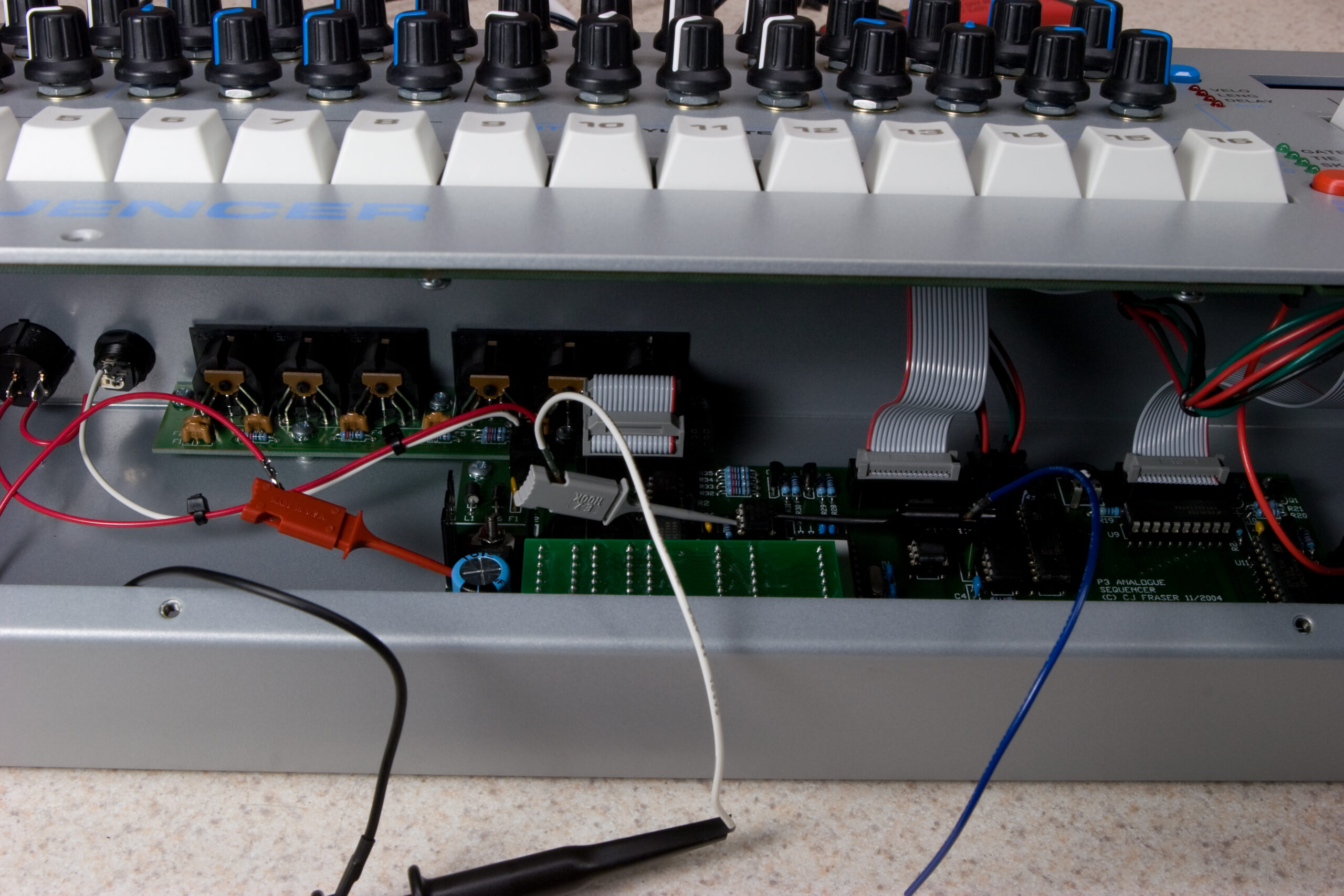
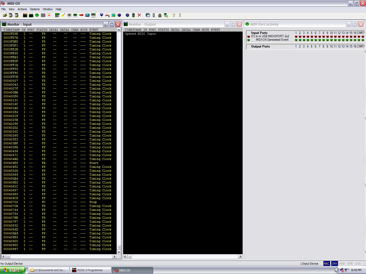
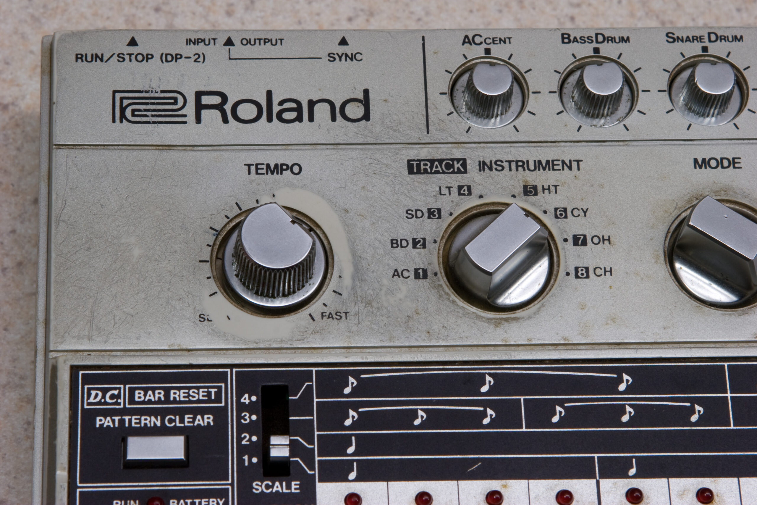
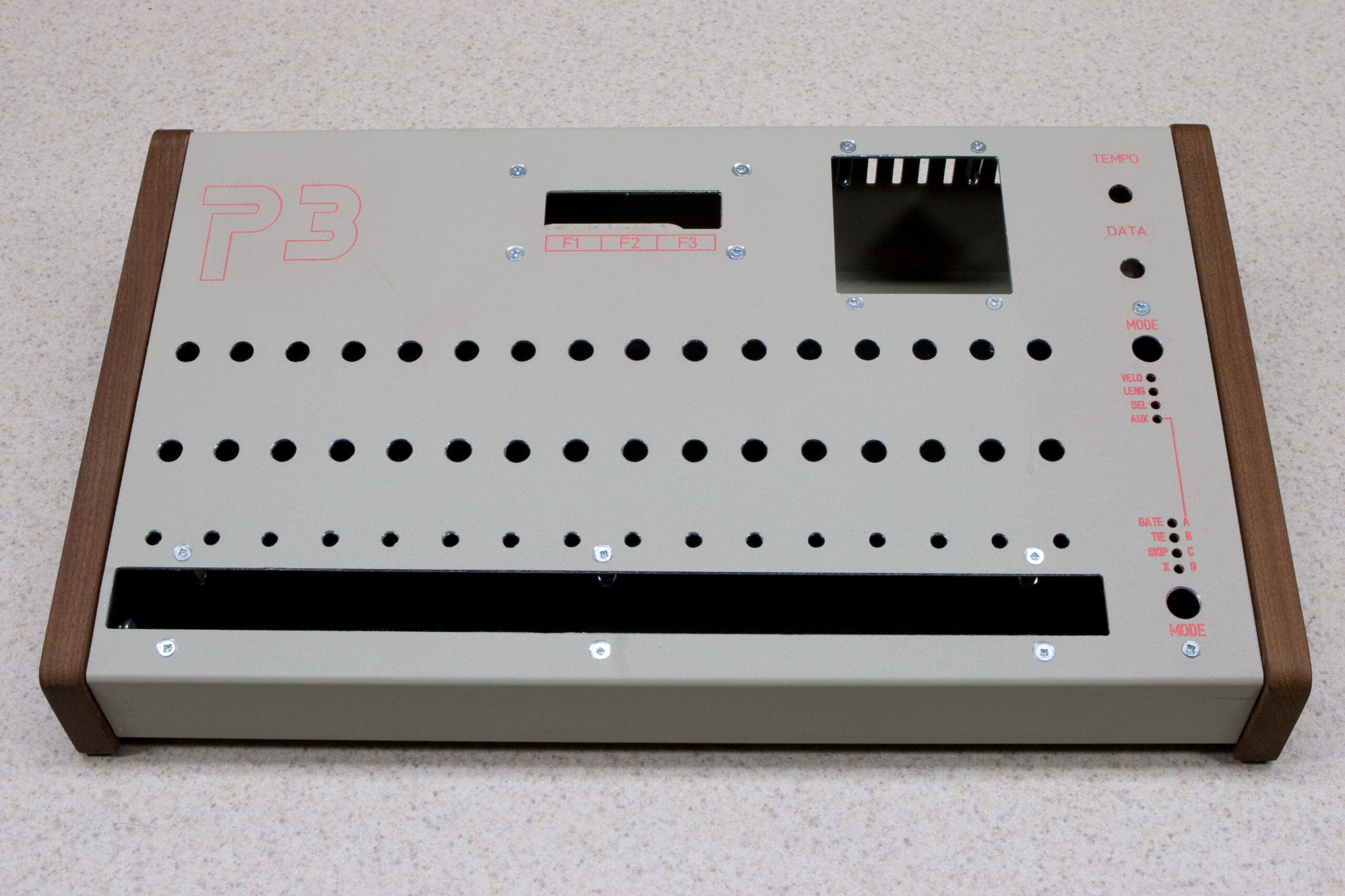
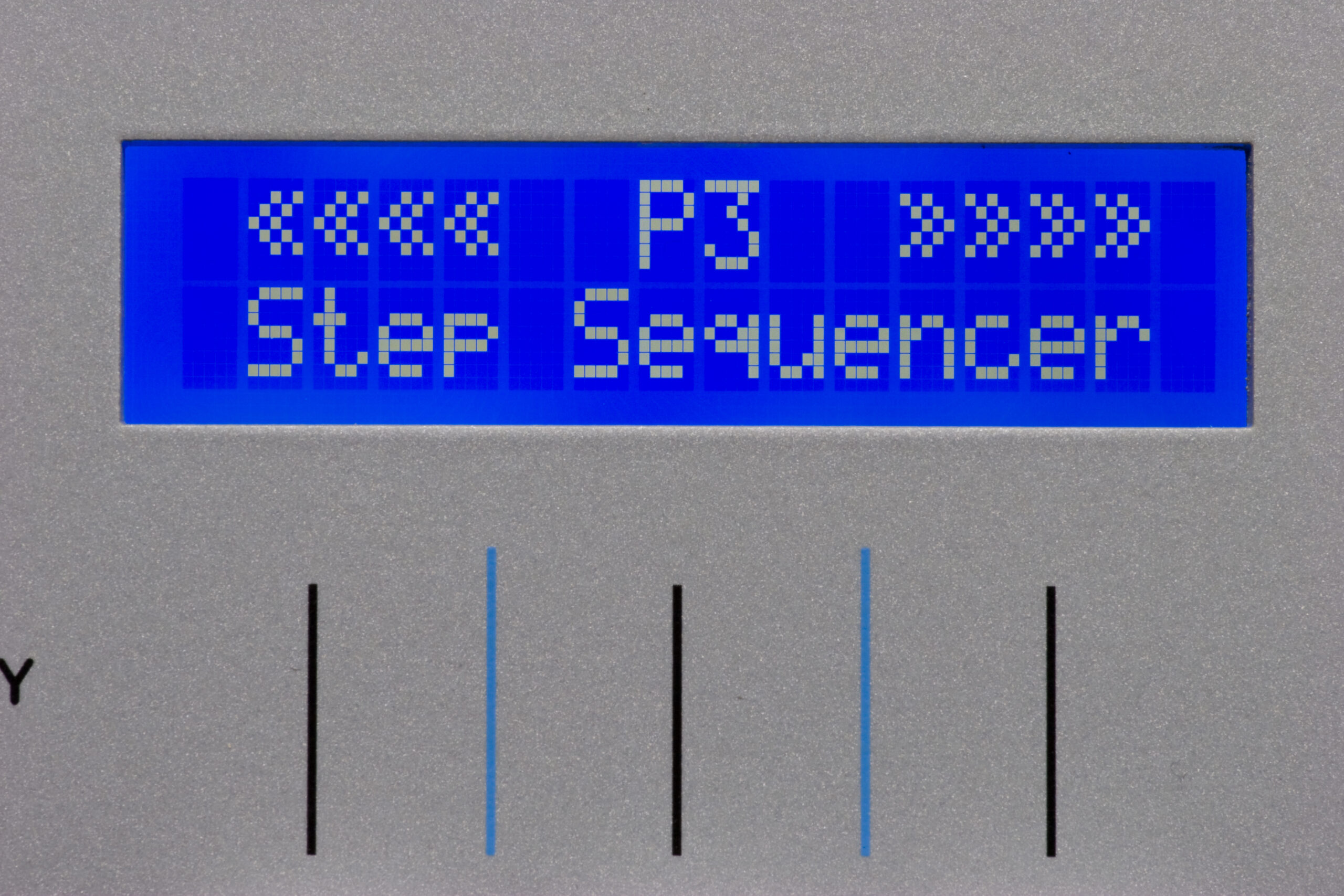
So, in wrapping up the testing of Ivan’s P3 I found one more problem: MIDI Sync output isn’t working. I think I’ve narrowed the issue down to the software running on the PIC which handles this. Here’s what I know as of last night:

· U1, the main CPU on the P3, has two lines coming out of it which either connect directly to the DIN sync port or to U19 used for conversion to MIDI sync.
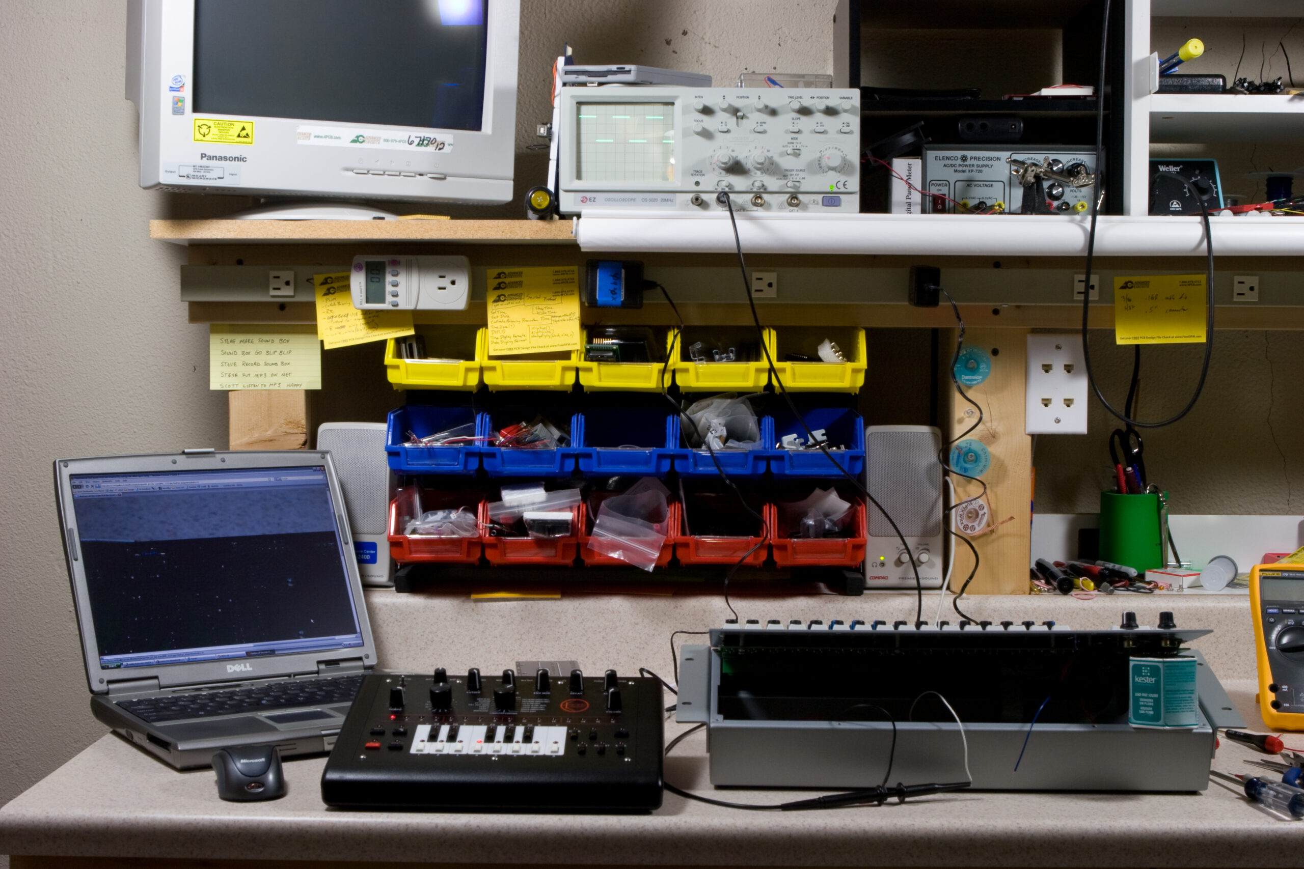
· I am seeing nice square waves on the PIC’s GP4, and these pulses change width with tempo change.
· The line running from U1 to the PIC’s GP5 goes high when the sequencer is running, then low when it isn’t.
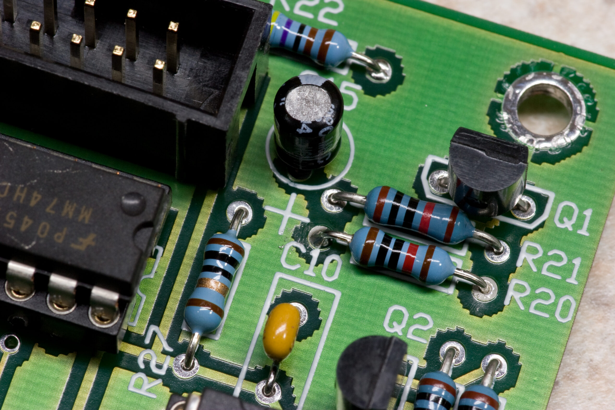
· I don’t see any data coming out of the PIC on GP0, which is what connects through a 220Ω resistor eventually through to the MIDI port.
· There are no shorts on any of the lines.

In troubleshooting the PIC itself I have:
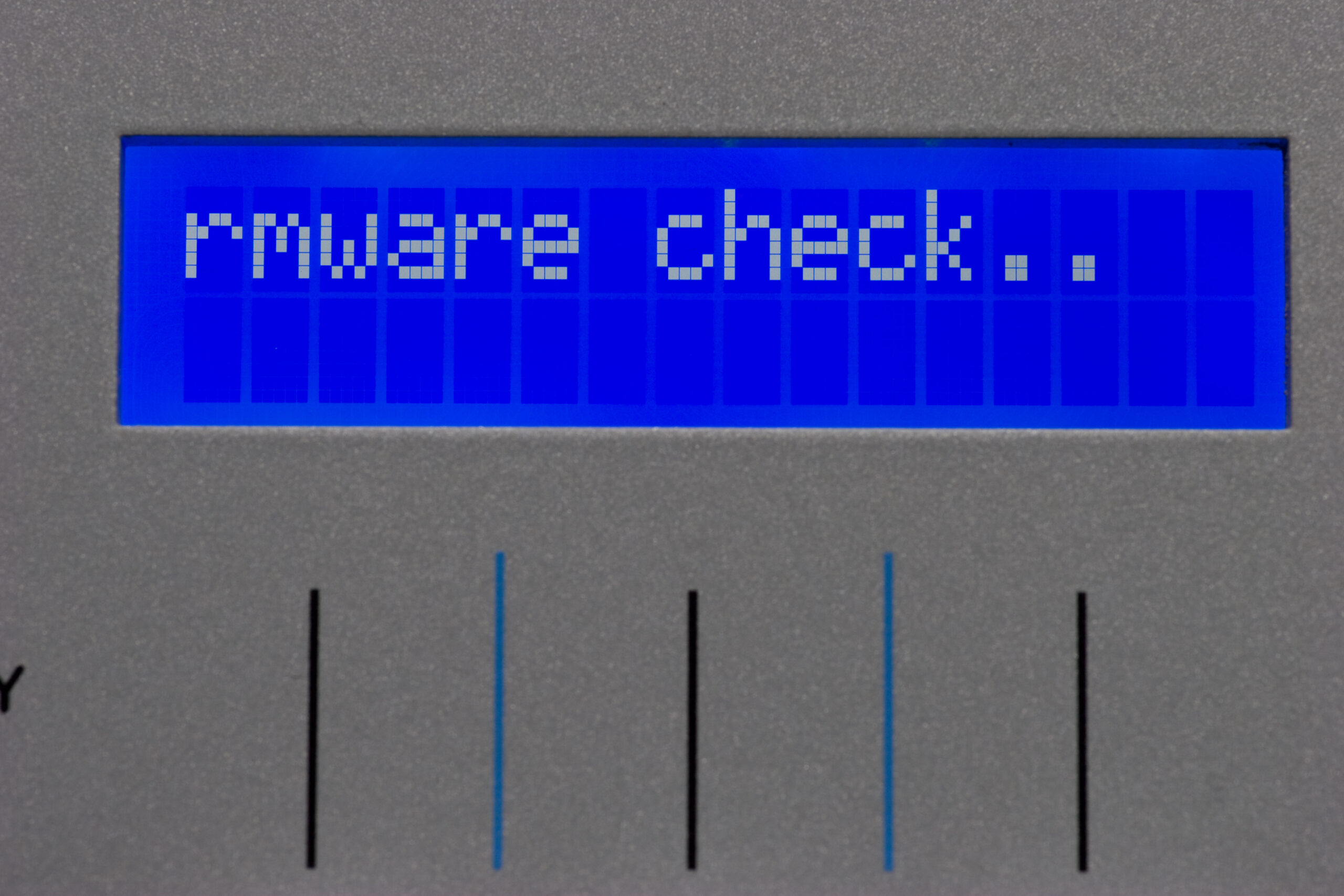
· Read out the firmware from the PIC, and received new firmware from Colin (the designer) for the PIC. These did not match, and the new firmware did not resolve the issue.
· Tried a spare PIC which I had sitting around in my parts pile.
· Wrote a test program to blink all GPIO lines on and off and successfully ran it on both PICs.
· Confirmed that the PIC is connected to power and ground and other lines, as expected.

After this, I pretty much have run out of ideas. This morning I threw the firmware Colin had sent me into a disassembler, and while I’m not very good at reading assembly, I think I’m that GP0 and GP1 are used as inputs and GP2, GP4, and GP5 are outputs, confirming that the firmware I was sent is for the v1.6 PCB. There is lots of BTFSS GPIO,0 and BTFSC GPIO,1 which are used for reading pins, and lots of BCF and BSF on GPIO,2, GPIO,4, and GPIO,5. GP2 (GPIO,2) seems to be used the most in the program, so I think it’s the MIDI port, and this would match what I see in my old photos of the v1.6 board, as GP2 connects through a 220Ω resistor to the pin header. GP4 and GP5 probably mirror the input received on GP0 and GP1, but I’m having difficulties confirming which pins are sync and which are enable.

I just pulled apart the older file which I had read out of the PIC previously and it seems to read from GP4 and GP5, with MIDI data going out of GP0. These port uses match my observations of the pinning of the v1.5 board, so I think that the older firmware looks somewhat right. That said, it clearly wasn’t working, otherwise I wouldn’t be posting this.

I think tonight I’ll try to write the originally-read firmware back into one of my new PICs, then I’ll drop it back in the P3, just to see what happens.

Oh, and for what it’s worth, this is my understanding of what the PIC12F629 on the P3, U19, does (or is supposed to do) on the the v1.5 boards: It watches for when GP5 goes high (an indication that the sequencer is running) and when it does, it sends out a MIDI clock message with each pulse it sees on GP4 (not sure if this is done at the rising or falling edge). It then stops sending these clock messages when GP5 goes low. On the v1.6 boards it seems to do something similar, but since it has three outputs I believe it also sends the DIN sync output as well.

There are also more photos of last night’s work at the bottom of this page in the last two rows.

UPDATE: One thing I didn’t test was input on the pins and the internal oscillator. I make a quick change to the blinky LED program to run from the internal oscillator and another version which I can use to test if all the inputs work. I’ll try that tonight. At this point it’s almost not enough for me to fix the problem, I want to know what wasn’t right.

Leave a Comment

Colin Fraser Saves The Day

R20 replaced with a 10K part, per Colin Fraser's suggestion, in an attempt to alleviate the issues with the LCD.

When I woke this morning I had received a response from Colin Fraser in regards to the problem mentioned in this post. He mentioned two things: the issue isn’t likely to be caused by timing because he specifically checks for the LCD to be available before writing to it, and that he has seen an issue where the transistor which enables the R/W line of the LCD doesn’t have enough gain. To increase this gain he suggested replacing the 22K resistor at R20 with a 10K part.

I did so as can be seen above and this is the result: a P3 displaying things properly. Thanks, Colin!

Now I just have to do a little bit more testing (I’m paranoid about these things), then I can pack up the P3 and send it back to Ivan. Of course, that will come after dinner. Danielle is in the kitchen with where they are making making naan and Mattar Paneer with this recipe from Manjula’s Kitchen. I’m looking forward to a very tasty dinner.

Leave a Comment

Odd LCD Problems in Ivan’s P3

For some reason, when booting the P3, it drops the first two letters of the 'Firmware check..' message. I'm not sure if this is the P3 mainboard booting faster than the LCD, or what.

Upon arriving home from work today I found a white box in the mail from Scotland indicating that the new LCD for Ivan’s P3 had arrived. This is the replacement that Colin (the Sequentix guy) offered to people as a replacement for PLEDs which had failed. After eating a bit of dinner I set to installing it.

Because of the spacing of the LCD and function switch board I had to file away a bit of the PCB in order to make it fit nicely. Thankfully Sequentix’s page on the replacement LCDs had mentioned this, so I was expecting to do it.

All in all, it went well. After getting the LCD working I installed the v4 firmware and MemX board, getting the machine wholly up to date.

I’m running into a bit of weirdness with the LCD, though. As can be seen on this page of photos, the display seems to be cutting off some characters during boot, corrupting others, and occasionally causing weirdness. I’ve tried making a new cable and replacing the IC directly connected to the LCD, but that hasn’t been successful. I’m really afraid that the controller on the LCD may be messed up. Hopefully tomorrow I’ll be able to use one of Ivan’s spare LCDs which he was sent (by way of me) by Crystalfontz as replacements for his failed PLEDs.

UPDATE: I just emailed Colin, the Sequentix guy, and asked for suggestions. After talking with a few people I’m starting to feel certain that the problem may simply be that the LCD doesn’t start up fast enough for the P3. It seems that with the HD44780 protocol the LCD talks the user can set up custom characters in the CGRAM (character generator RAM). While I may be way off base, I’m thinking that the P3 sets up the special characters it needs on boot, then tries to display stuff. I think that if the LCD isn’t running stable yet then these characters, along with data written to the display controller itself, could become corrupt or lost, displaying the symptoms like what I’m seeing. Hopefully I’ll find out for sure soon. If this is the problem then a fix would simply require the P3 to wait for another 250ms (or so) at power-on.

Leave a Comment

Roland TR-606 for Jan

Detail of the area around the tempo knob on the TR-606 showing that it's worn down to the paint.

Today after getting home from work I ate some carrots and hummus and hopped on my bike, intending just to run up to the bank and go to the ATM. Instead I ended up going to the ATM, then winding my way through industrial parks up to 24 Mile and M-53, where I turned around under the bridge after coming across this amusingly broken set of toy guns. I then wound my way home, taking time to ride through every industrial road / park I came across, racking up a total of 15 miles.

Yesterday I received this box in the mail, and tonight I opened it and grabbed some pictures. See, a guy by the name of Jan Czmok, who is the only person (that I know of) besides me to build a complete MIDIbox SID-NUXX (you can see his photos of his here) wanted to buy a for-repair TR-606 on eBay, but the seller would only ship to the US, so I’m relaying it for him. Here is a mirror of the auction, if you’d like to see it. For reference, the auction closed for $255.

I wish him luck in fixing it up because it’s not in particularly good shape. While it doesn’t seem to have a smell, the damage to it makes me think that it was either left in a garage for a few years, that it survived a flood, or maybe that it was just left at the bottom of a septic tank full of angry lobsters.

If you would like to see the full photos of the TR-606, click on this link.

2 Comments

Trail at River Bends

Riding from my house to the trail at River Bends Park, out to Ryan Rd, around the old Nike site, and back home.

I actually managed to leave work early enough today that I was able to go for a nice bike ride after work. It was only 1:16 and just over 16 miles long, but it felt good. I made my way from home over to River Bends Park in Shelby Township, then headed down the foot / bike trail through the woods. This is a 2.5 mile winding trail with some nice hills, sharp turns, and interesting things to look at. I found that the tires I have are pretty okay for this sort of trail riding, except on parts of the path. Oh, and I also found that moving quickly through a swarm of bugs while breathing heavily through one’s mouth is not particularly pleasant.

Since I’m uncomfortably stinky, and because I finally stopped at Trader Joe’s on the way home and purchased more deodorant (I’ve been out for a week), I think I’ll go shower. Oh, and my new server was actually delivered today, so I think I’ll unpack it and grab photos of it post shower. I also might try a new (to me) Southern Tier beer called Back Burner, but I’m not sure… Maybe I’ll just let that wait for tomorrow. I’ve already got enough things I still want to get done tonight.

Oh, want the KMZ of today’s ride? It’s here: 24-Apr-2008.kmz, and here it is in Google Maps. Please excuse the two tracks. Google Earth can’t merge tracks (I imagine there is a good reason for this), my GPS decreased the resolution when saving the current log to a file, and it seems that multiple Active Logs had to be created to deal with the number of points I was generating today. Oh, yeah, I decided to try doing one-per-second points which, as you can see, has resulted in a much smoother route plot. It’s too bad this relatively short ride filled 49% of the memory on the GPS. Maybe I really do need an SD based GPS data logger…

Leave a Comment

Failing PLED?

Two lines of display on the failing PLED during bootloader update. Note that the second line is more faint than the first, pixels are smaller than expected, and there is distinct fading around the edges of the display.

Last night I made quite a bit of progress on Ivan’s P3, getting it up and running, but I did run into a few problems. First, as can be seen above, the PLED which came with the enclosure seems to be failing. It will either display no text, one line of text, or (rarely) both lines, and every time pixels seem small and dim, with the edges of the display fading to nothing. Only a power cycle of the P3 seems to (re-)activate non-working parts of the display. As the P3 still functions even when nothing appears on the display, I believe that it’s actually the display elements of the PLED which is failing.

Here is the PLED in my P3 from 2006, and when it is compared with these two images (1, 2) of the PLED from Ivan’s P3, it seems pretty obvious that something is wrong.

Thankfully there was a spare PLED in the package of parts I received, so tonight I’m going to try that one instead.

Second, I’m not happy with the cables I made for connecting the tempo and data pots to the mainboard, so I’m going to remake them. The tempo pot connection seems to be a bit flaky, so I’m not sure the pins are properly seated in the connector. The cables are also short enough that they are difficult to connect, so I’ll probably redo them with braided 24 gauge hookup wire or something like that.

Finally, the v1.5 mainboard construction notes indicate that when the P3 is being set up for MIDI sync, D2 and D3 should be replaced with 220pF caps in order to add a bit of extra capacitance to the lines to work around false triggers. I didn’t have any 220pF parts, and none came with the kit, so I instead used 330pF parts. I don’t believe this will be a problem, but I made a post to the analogue-sequencer group asking for confirmation.

Beyond those three problems, the build is going quite well. I’m very happy with how both the step board and keypad came out. The IDC ribbon cables, their connection, and power input stuff also worked out great.

I was also able to get the latest bootloader and v3 firmware on the P3, which means that as soon as the other issues are sorted out I can get the MemX and latest v4 beta installed. After that it’ll just be time to install the knobs, test it out, and ship it back to Ivan.

Leave a Comment

Good Progress on Ivan’s P3

Detail of the bank of 12 resistors in the lower right corner of the mainboard PCB. I like how these look once fitted.

Today I made a bunch of progress on the Sequentix P3 I’m currently building. Before today I’d only checked out the parts to be sure most of them were there, looked over everything, and did some general setup to be sure assembly could progress. Today I started fitting pieces, and I’m definitely more than half done at this point.

Because this P3 uses a slightly older board set (v1.5) I had to use this set of older DIY Sequentix P3 directions, but this didn’t prove to be too difficult. While I was able to complete the mainboard, I had to make some slight modifications. It seems that the v1.5 P3 board set only supports MIDI sync or DIN sync. One must read carefully through the main board and IO board pages to figure out what extra components to add, which to leave out, and what to do differently. In short, I had to leave out some parts from the mainboard and fit two capacitors where diodes once went and add in an extra pullup resistor on the bottom of the board.

The two capacitors on the top of the board are intended to add a bit of capacitance to the input lines of the PIC which handles MIDI sync. It is suggested that 220 pF parts be used, but as I didn’t have any of them I fitted some spare 330 pF parts. I don’t think this will cause any problems, and hopefully it won’t. The extra resistor on the bottom of the board is to help work around slow rise times on the MIDI output caused by additional capacitance brought about by the inclusion of RFI filters on the IO board.

I’m hoping to be able to power it up for the first time either tomorrow or Tuesday. How late I get home from work will determine how much I’m able to get done each night.

Here’s a few more photos of parts from tonight:

· Completed Mainboard w/o ICs: Top / Bottom
· Completed upper and lower pot boards.
· Pots for the P3, plus spares, with lugs removed and thick 1/4″ washers fitted for spacing.
· Completed IO board, set up for MIDI sync.
· Completed function switch board.
· Twelve resistors.
· Incomplete keypad board with 1N4148 diodes fitted.

Leave a Comment

GPS Logger and Bike Riding

As shown earlier and resulting some KMZ files, I will frequently clamp my GPS to the handlebar of my bike and log where I’ve ridden. The problem I’m finding is batteries… The older Garmin eTrex Legend that I have will chew through a pair of disposable AA in an hour and a half, and good rechargables don’t last beyond three. This is short enough that it’s starting to become a hassle to use the thing. On top of that, dumping the data into a computer sucks down even more battery.

I’m thinking that my next electronics project should be a low power GPS logger that either writes to some local flash, or to a microSD (or whatnot) card. I think that one of the random modules from SparkFun, a PIC, a off the shelf FAT library, a FT232R could make it all work nicely. It could recharge via USB and have a couple basic buttons and LEDs for resetting saved logs or whatnot. All I’d need to do is ensure that it’s in a standard format (shouldn’t be hard) and GPSBabel will be able to make it anything else I’d want.

Now, since I just rode ~21 miles, I’m going to go shower then get back to work on Ivan’s P3.

Oh, and look at this: FTDI’s USB to USB null modem cable (PDF Flyer). I could really use one of those too.

Leave a Comment