Sequentix P3 #008 Continues
Last night I did a bunch more work on the Sequentix P3 that I’m building for Mark Pulver (photo gallery retired). Unfortunately last night was the time where I started to see issues with the project. In short, I now understand why Colin moved away from not very many people used this case design for the P3†. On top of the poor button / pot / LCD layout, the tolerances on the case just aren’t very good.
Here’s a rundown of the problems:
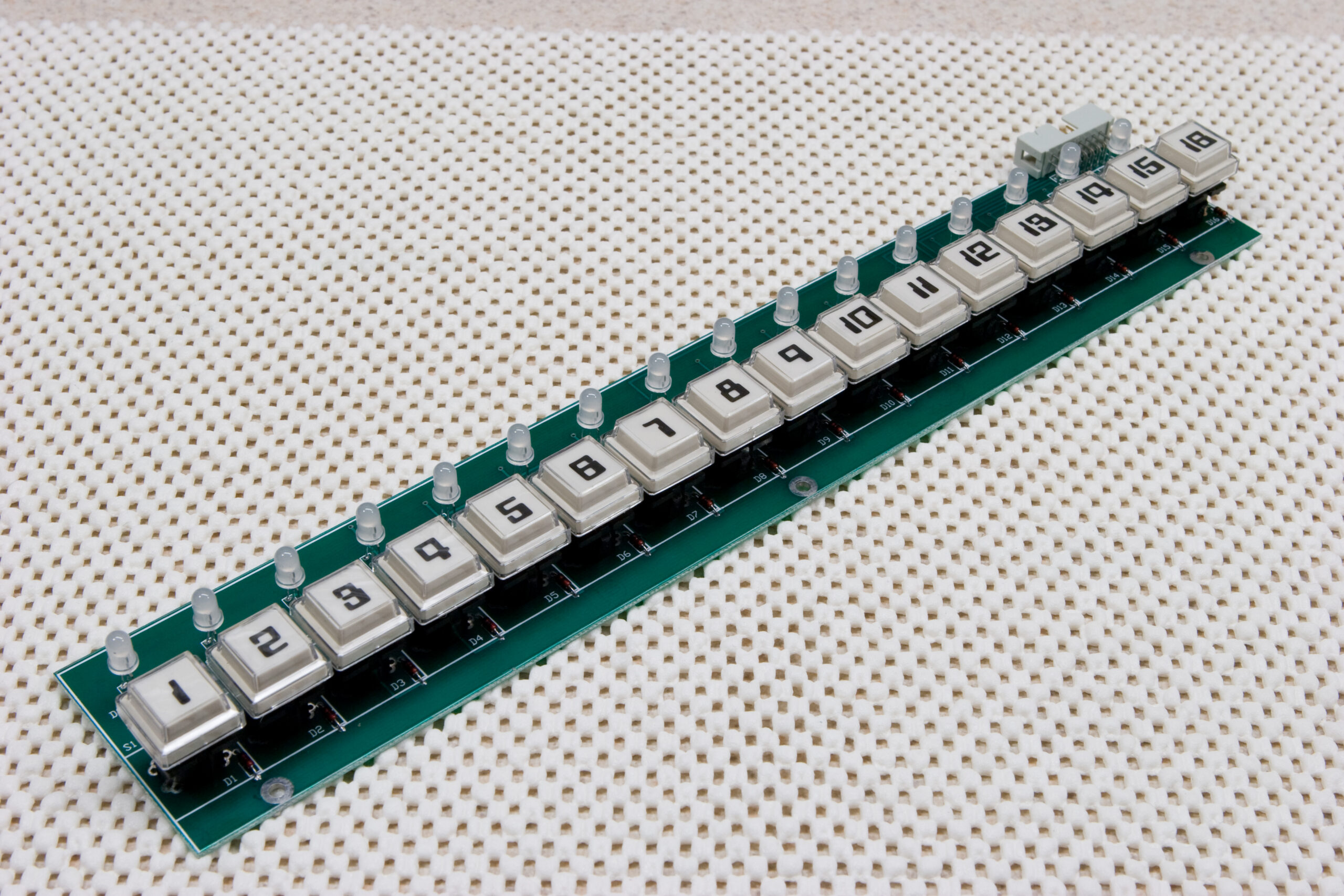
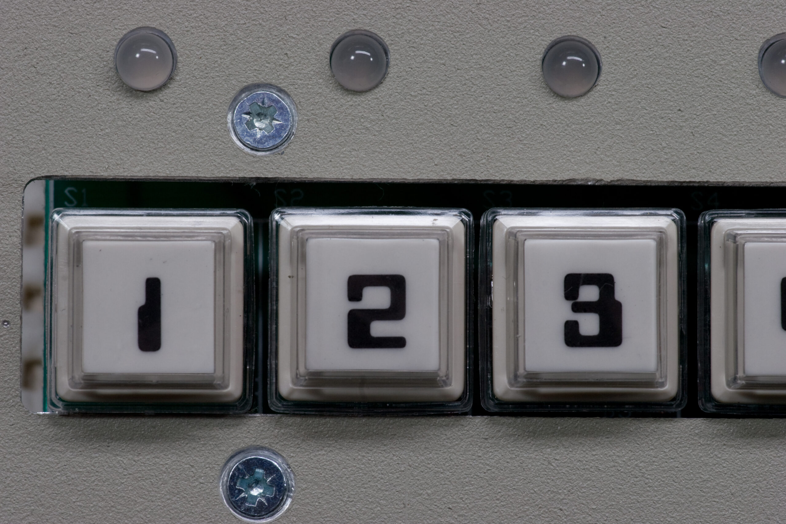
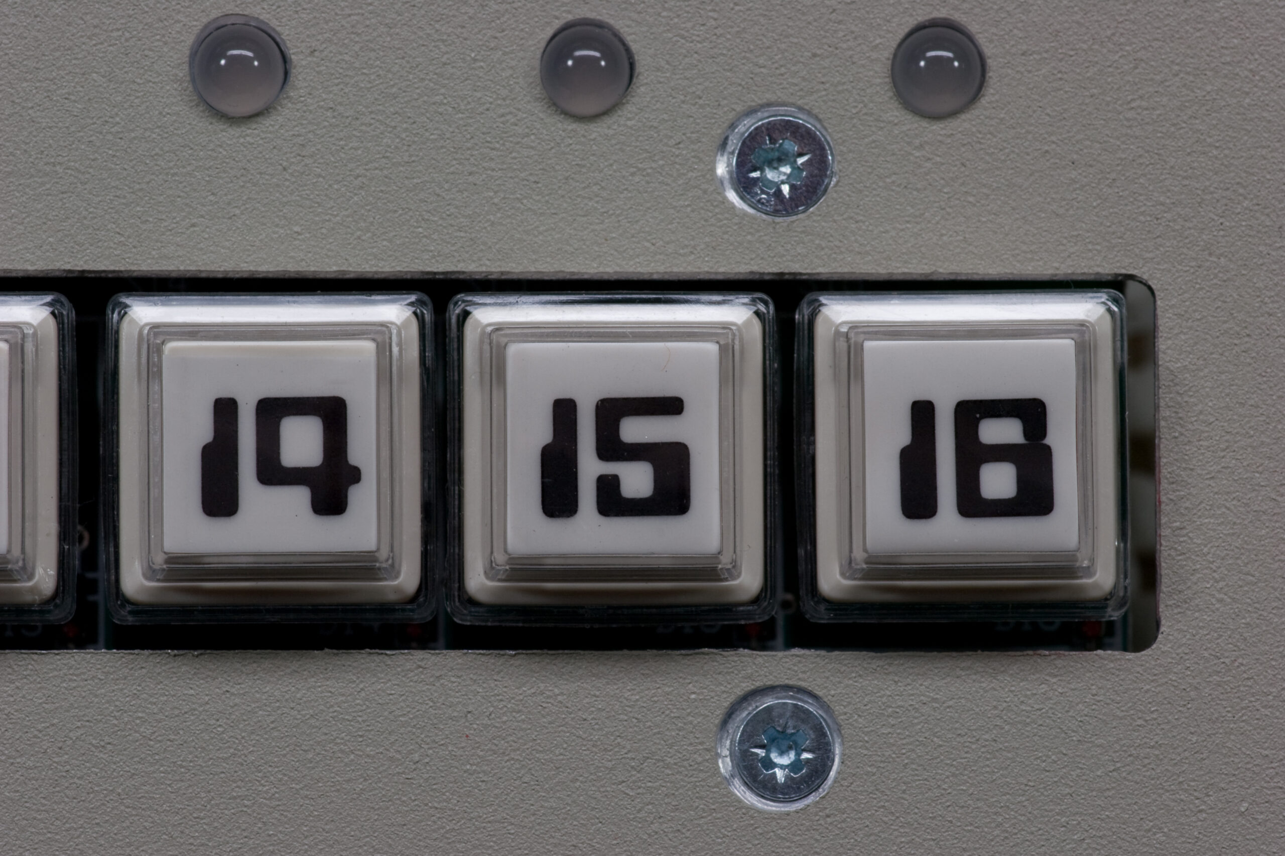
Step Switches: I fashioned a jig to hold the 1-16 buttons in place on the step switch / LED board, and that worked rather well for aligning all the buttons in a nice row, and they automatically lined themselves up with the holes in the PCB. Unfortunately, the screw holes for mounting the PCB aren’t perfectly in line with the slot cut out for the buttons themselves. The end result is that on the left side of that row the buttons are about 1mm lower than on the right side. The buttons all work fine, but they just look a little off.
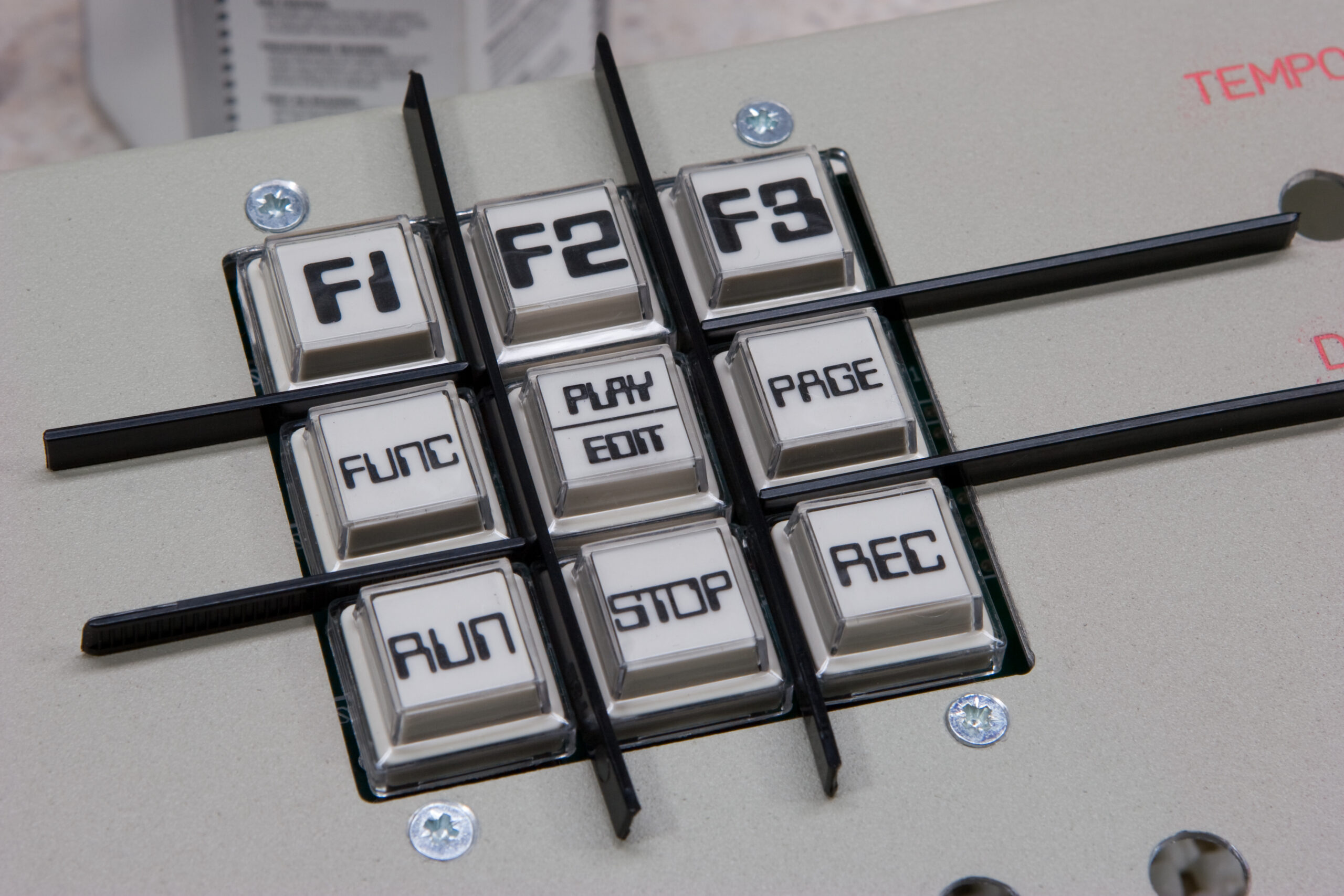
Function Switches: The way the holes are drilled for the function switches, along with the alignment of the screw holes, the red (key function) button rubbed a bit in the hole. A little bit of filing cleared this up.
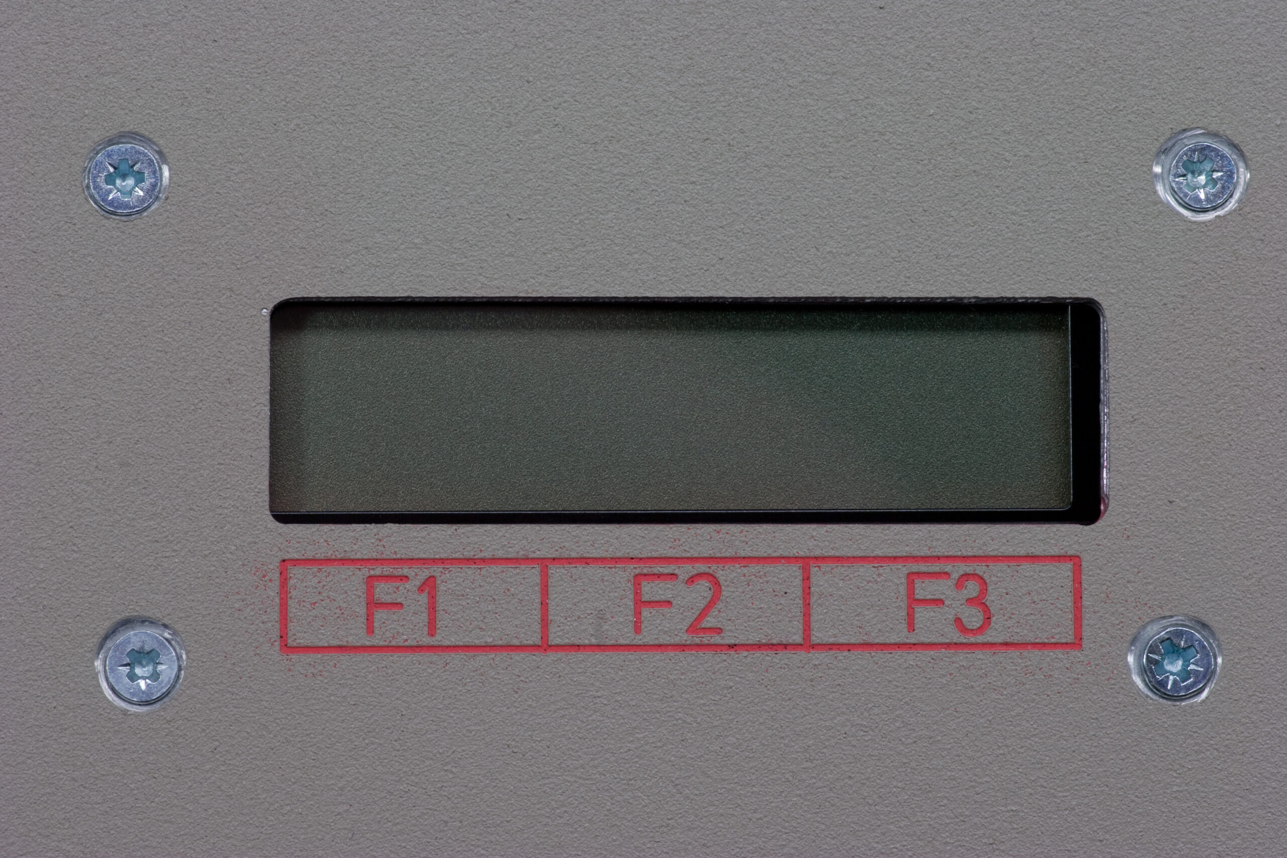
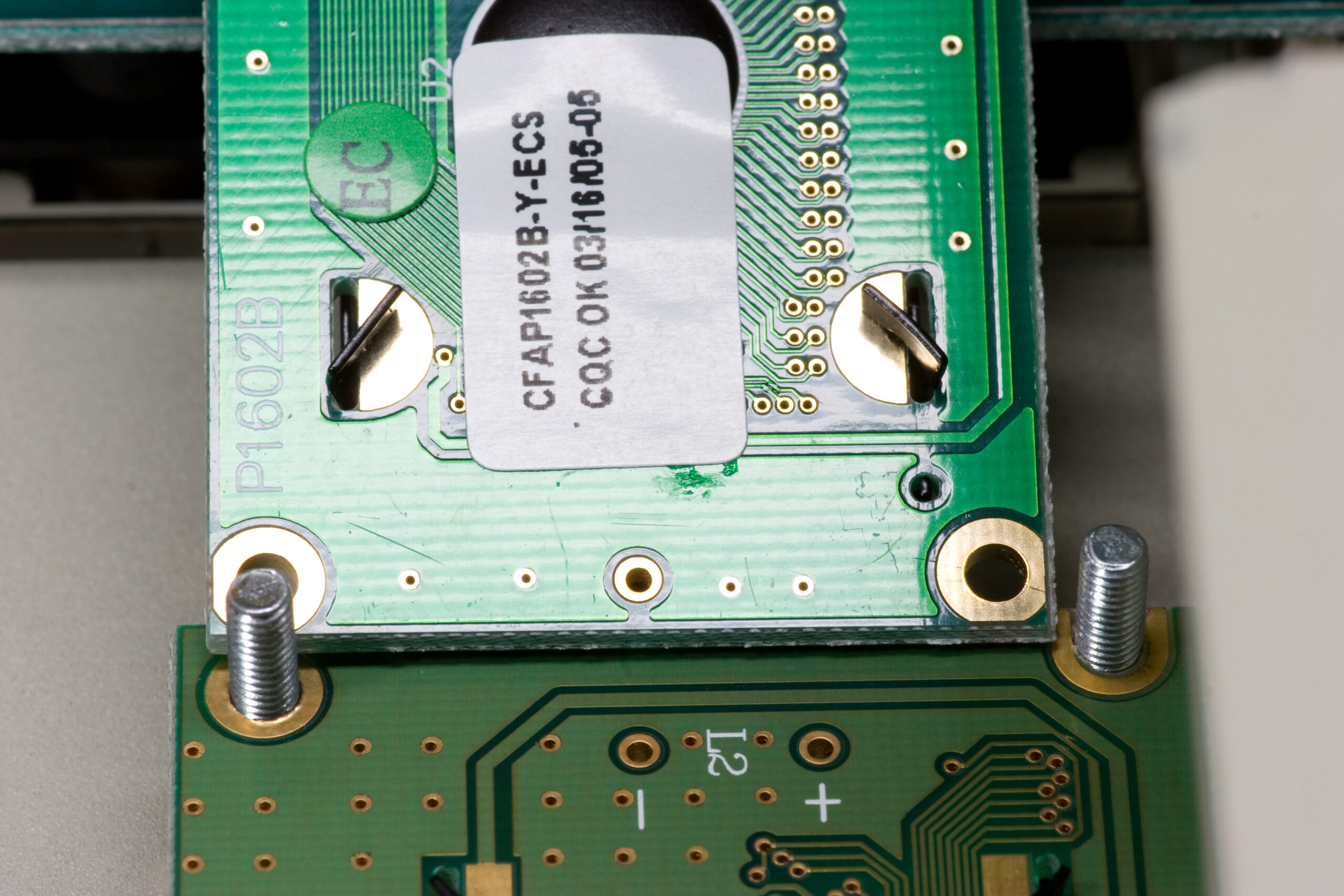
LCD Alignment: With the stock LCD for this original P3 enclosure fitted, it doesn’t quite line up with the hole cut for it, leaving the bottom and left side of its bezel visible. This may not be an issues as the actual displayed data will likely be centered, but it doesn’t look as good as it could. Additionally, the mounting holes are not physically compatible with one of the PLEDs used in later P3s. It may be possible to get the PLED to fit, but this would require a bit rigging, possibly involving cutting the corners out of the PCB and fashioning some sort of mount.
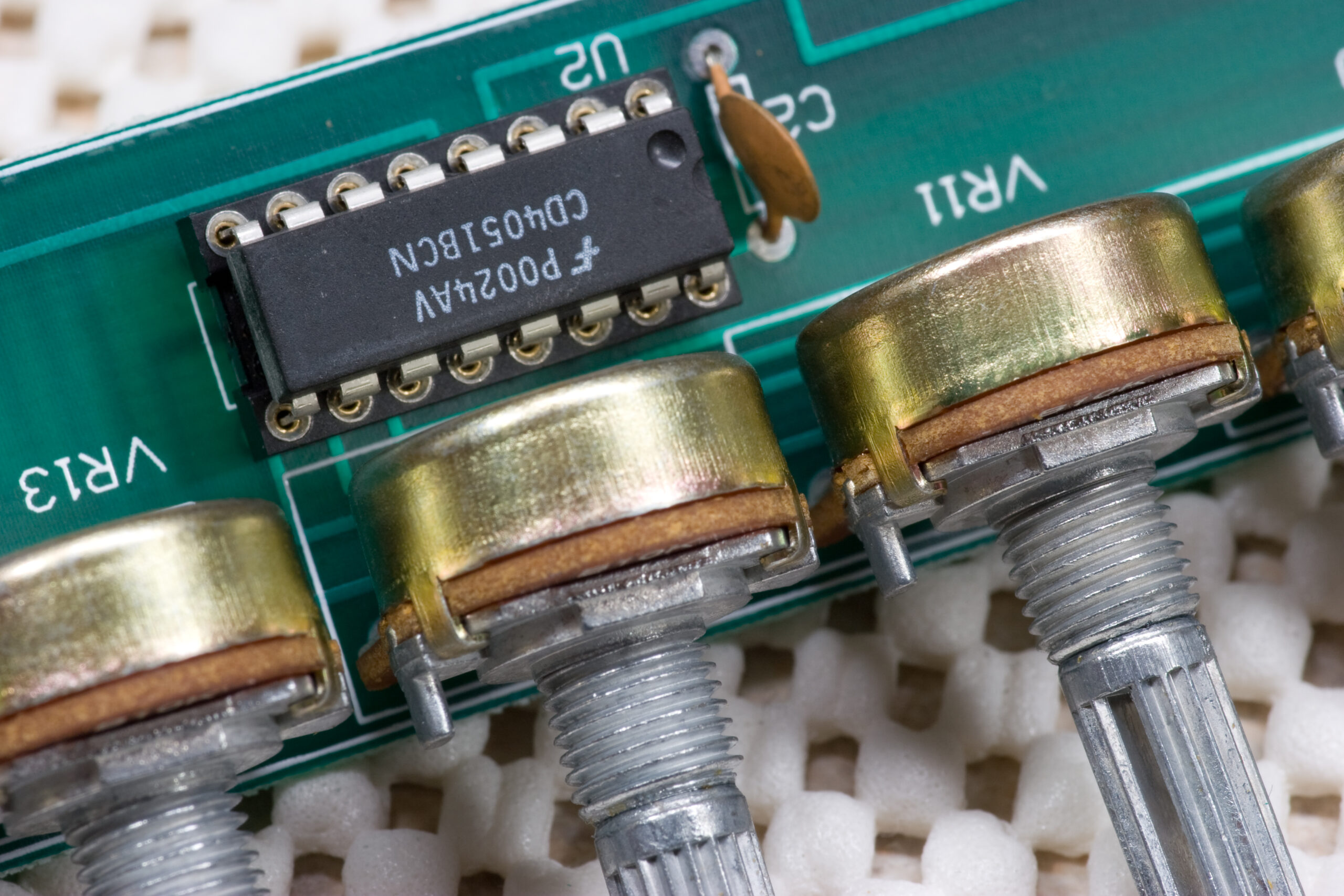
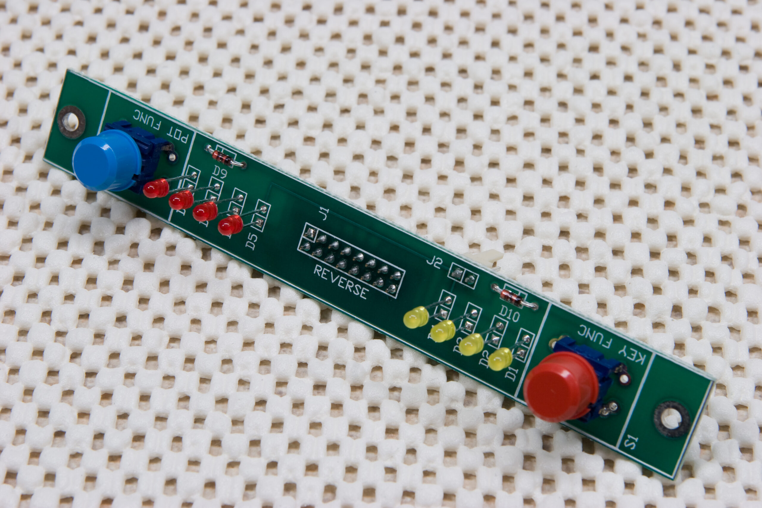
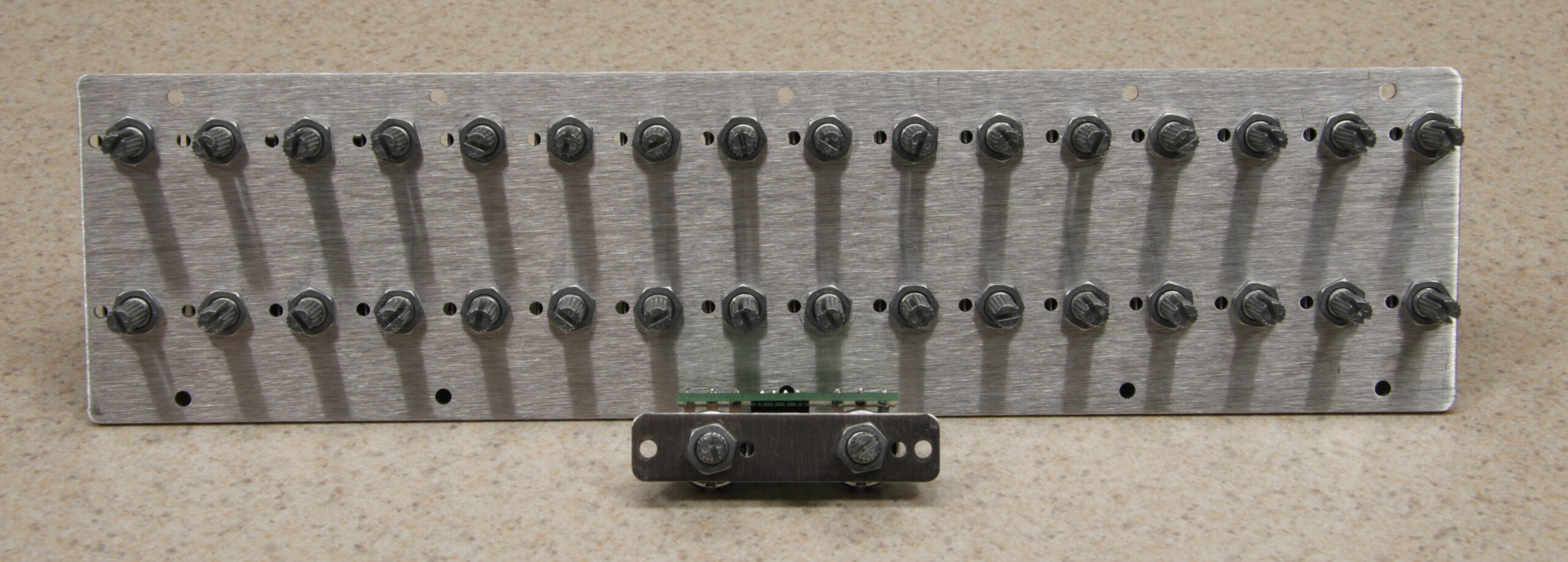
Potentiometers: The P3 uses analog pots for a number of inputs. This works very well, except pots (as seen above or here) have small tabs sticking off of them. These tabs are normally fitted into drilled holes and they keep the pots from rotating during assembly or use. The subpanels for the newer P3 enclosure have holes for these tabs, but the original enclosure on Mark’s P3 doesn’t. Because of this, if I were to tighten down the pots they would be bent to the side. To work around this I’ll just snap off tabs (a trivial process, really) and then stack some washers between the panel and pot body to space things as nicely as possible. This will allow the mounting hardware on the pots to be properly tightened.
Now, that out of the way, the good things: I had no problem getting all the LEDs fitted / mounted / nicely aligned in the panel. These are all soldered into place and the PCBs holding them can pretty much be removed at will. All ICs have been fitted into their sockets, and things are progressing quickly towards the ever-so-scary first powerup.
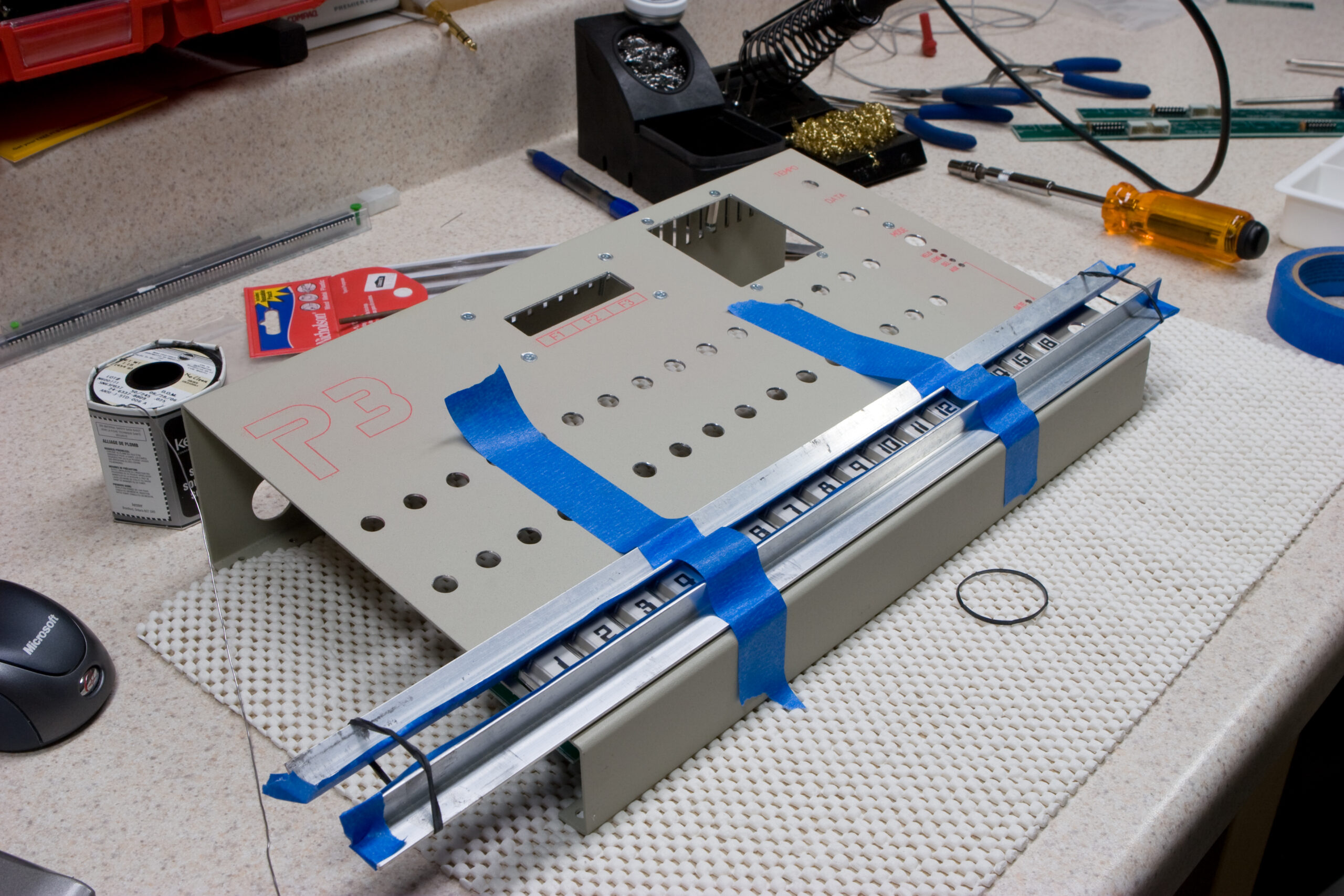
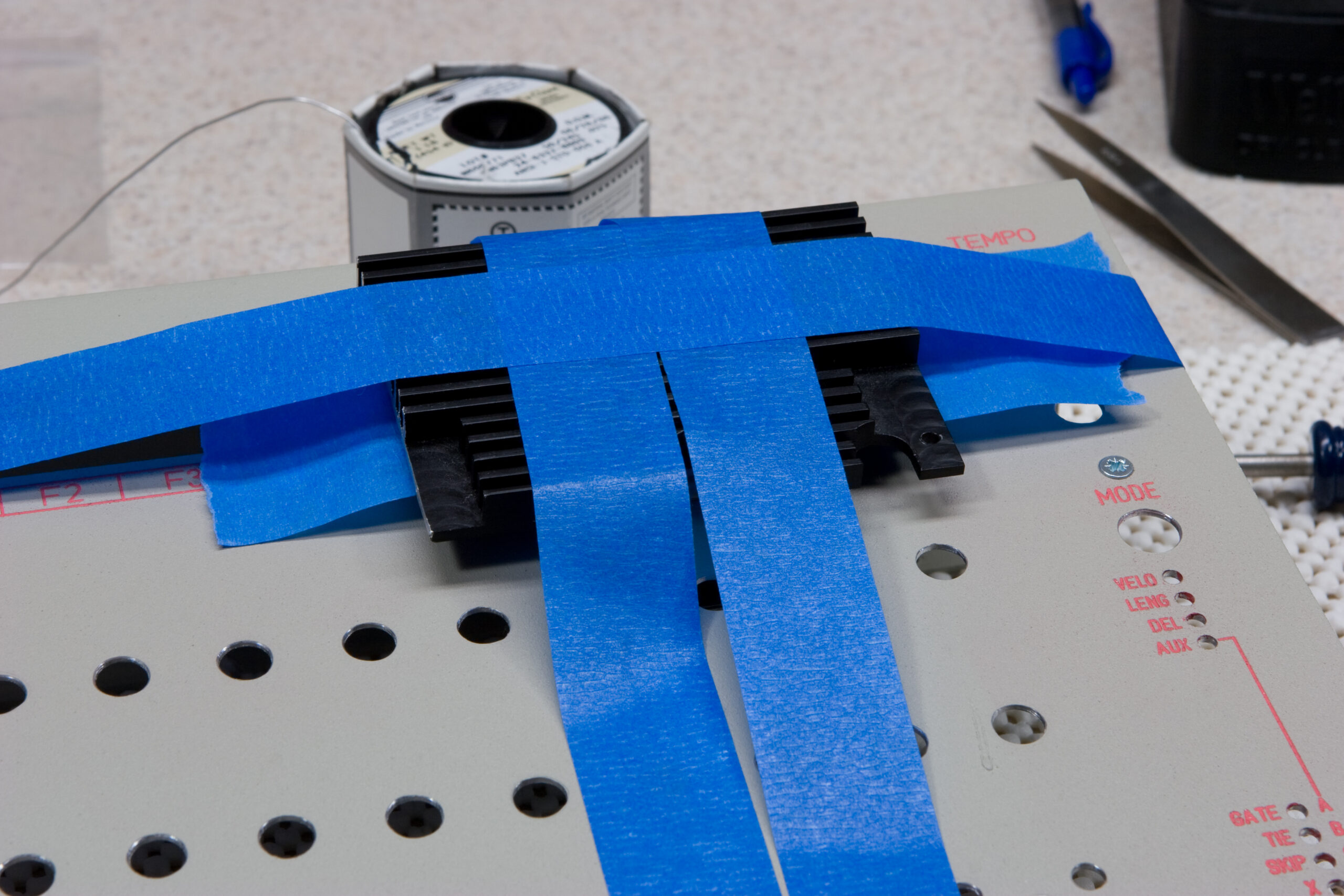
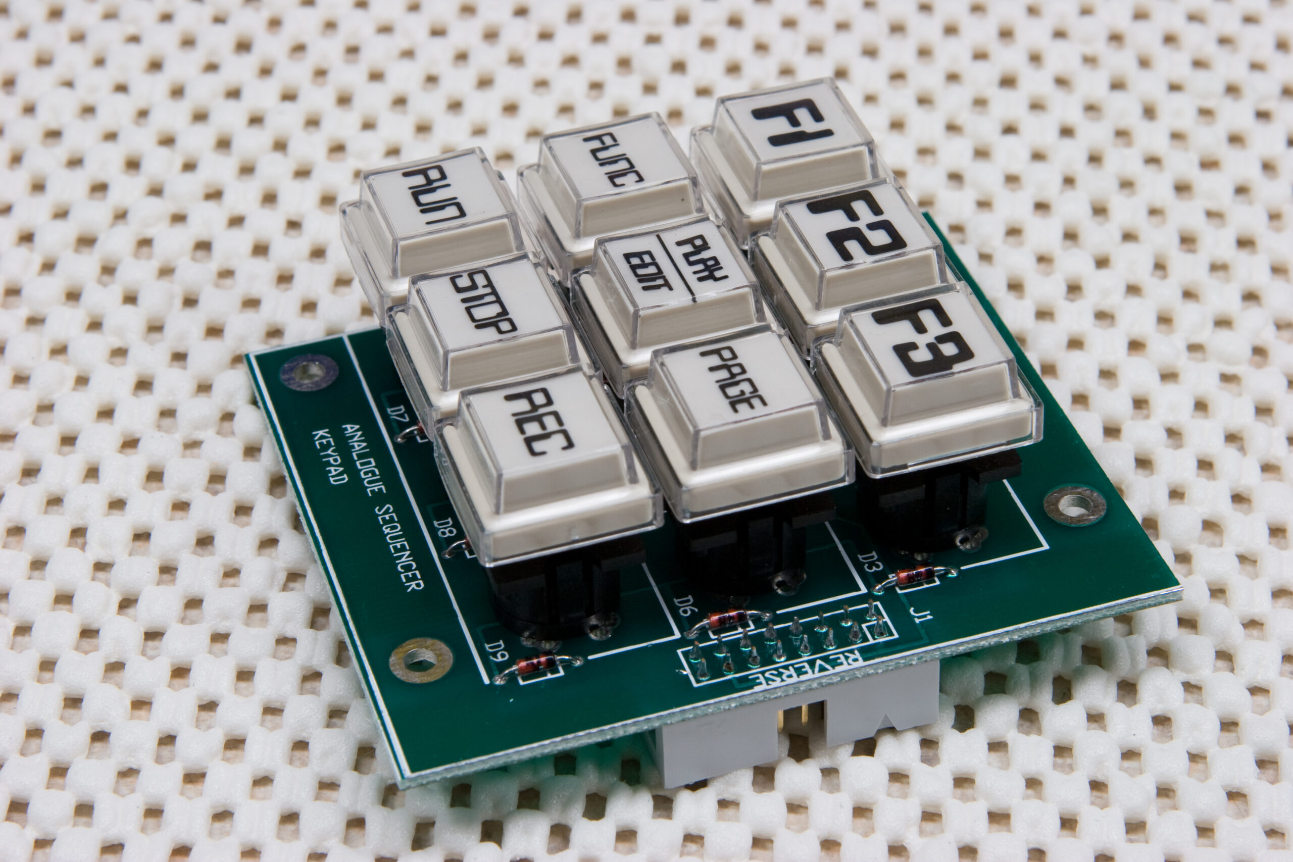
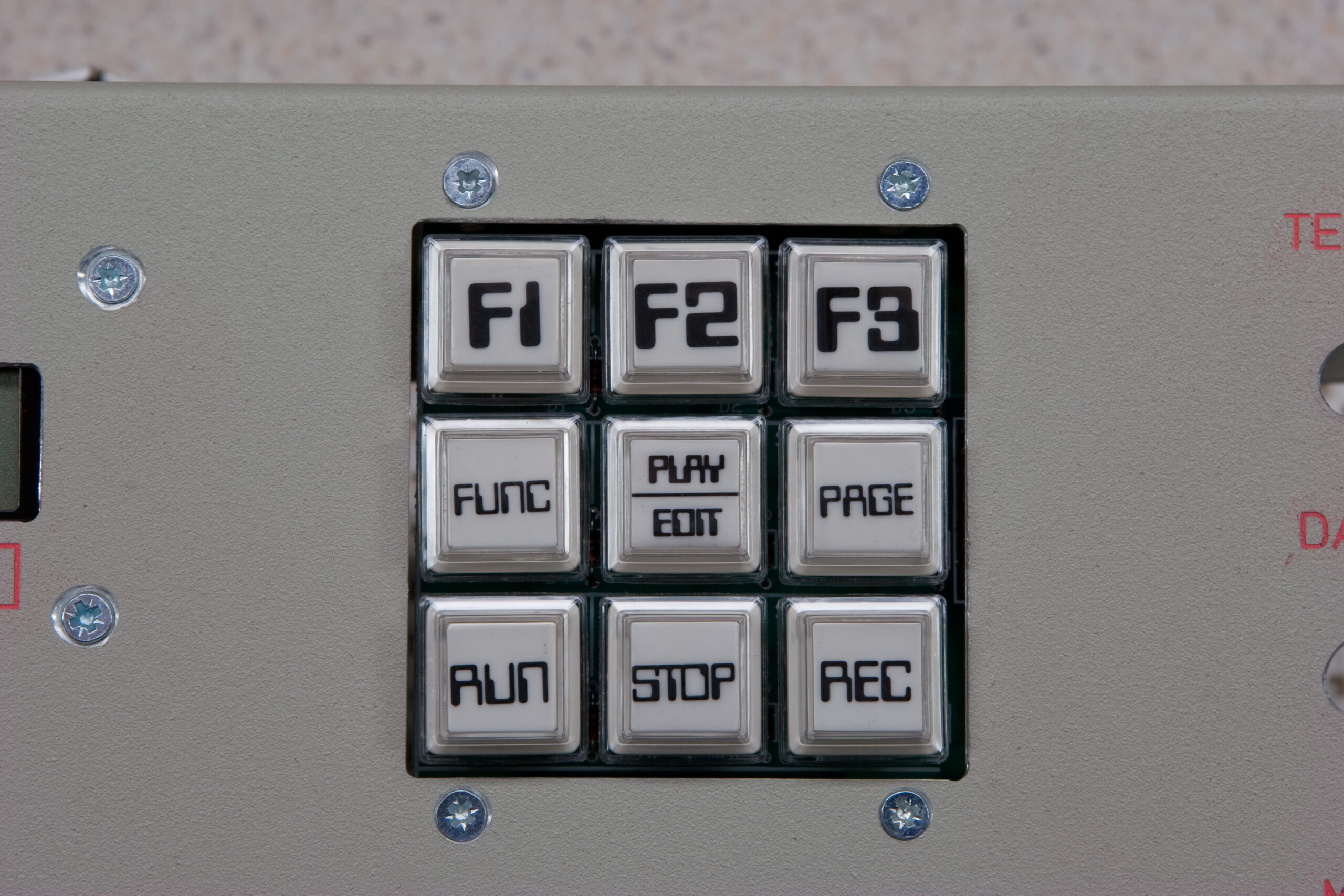
Oh, I also had no problems making a jig out of cable ties and an old heatsink and blue masking tape to handle alignment of the keypad. I’m really happy with how it came out, and thankfully its mounting is not misaligned in the front panel like the other keys.
Next, and hopefully tonight, comes the boards and pots and switches and such together, finalizing mounting of the pot boards, and hopefully getting it running for the first time.
† After making this post, Colin Fraser corrected me with regards to the case design. This case is actually the Maddox design. The original Sequentix P3, of which only four exist, can be seen here.