Sequentix P3 #008 Is Working
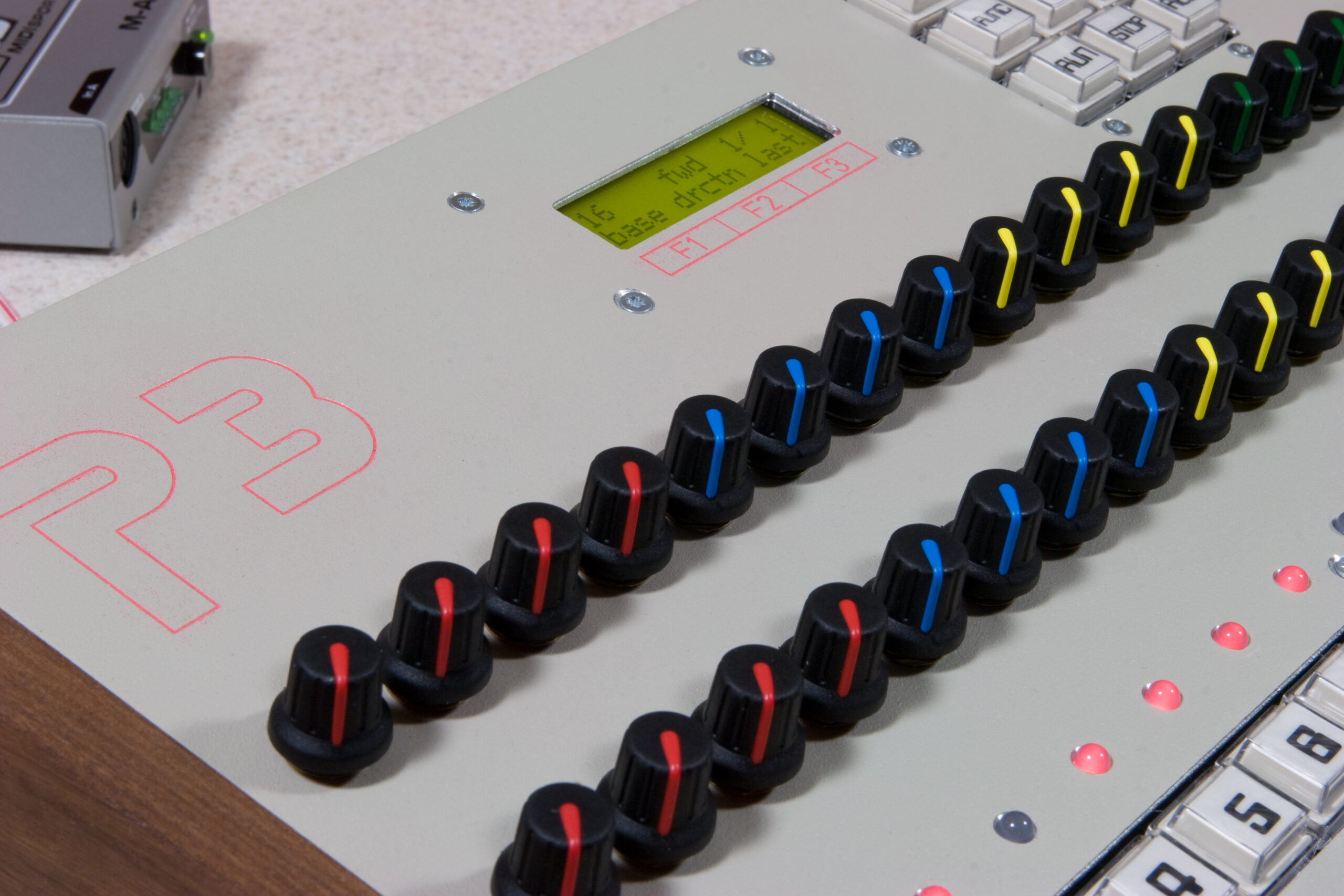
It works, it’s running with one of the v4.00 beta OS’, and it’s almost done.
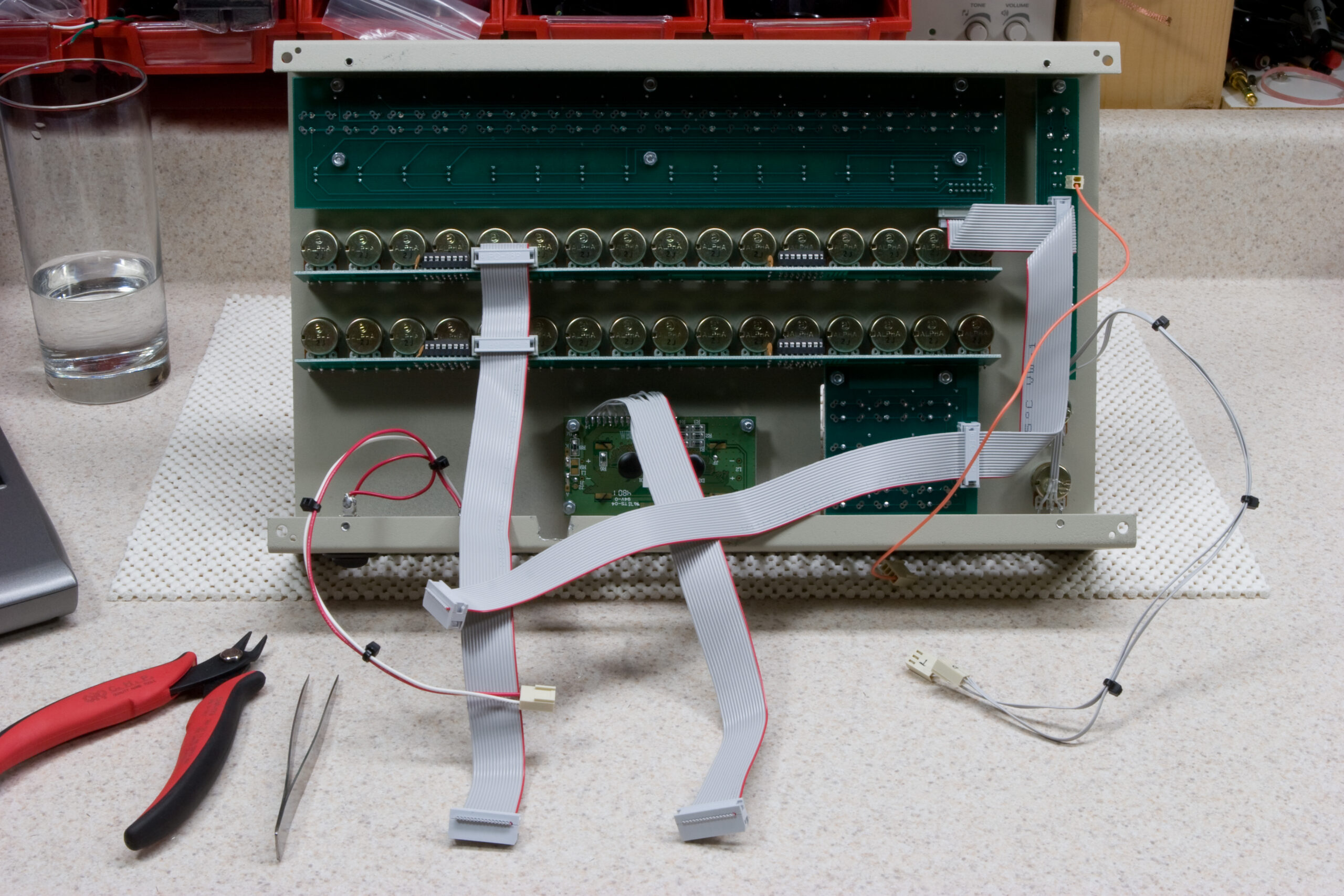
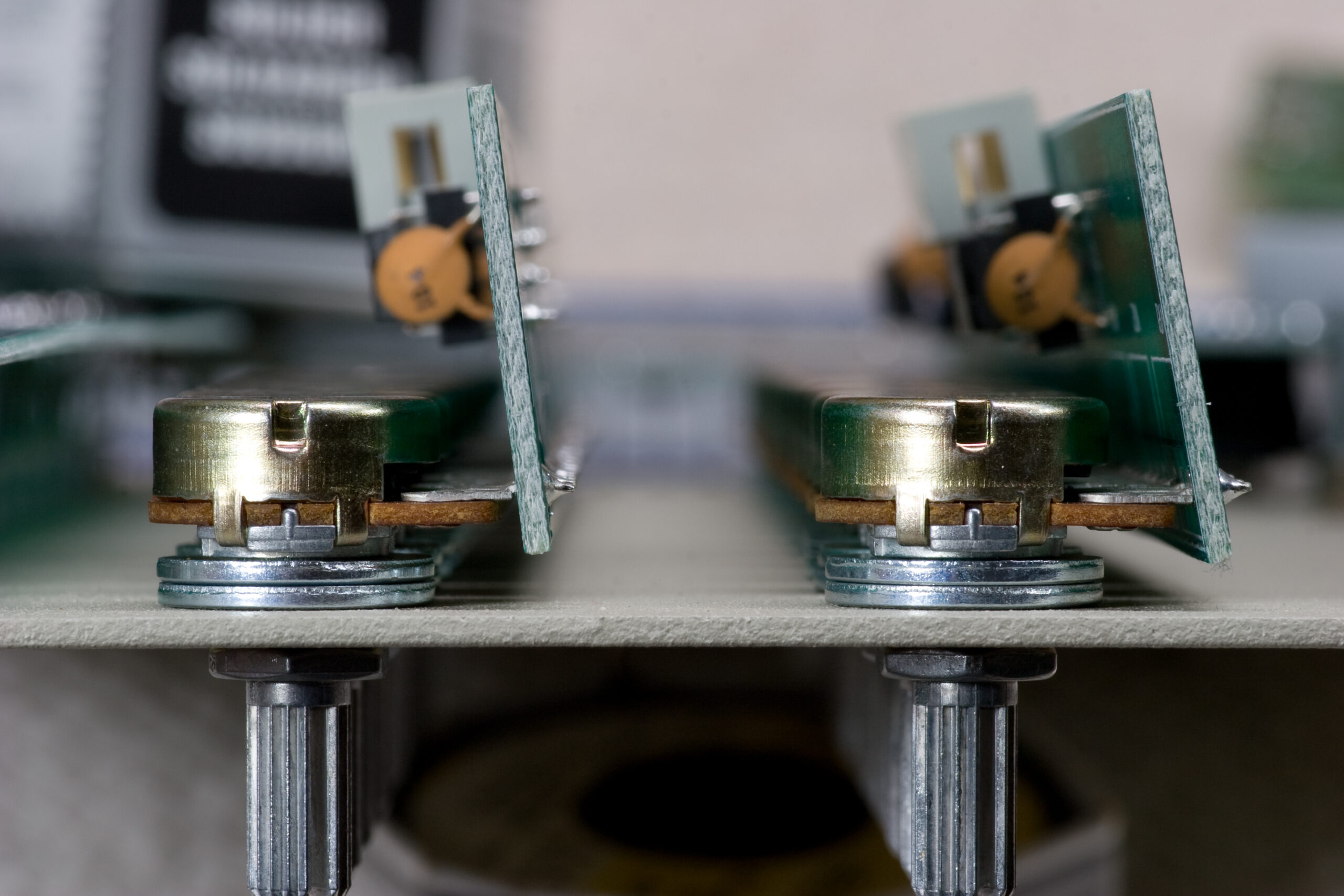
Tonight I did most of the final work on Mark Pulver’s Sequentix P3 (photo gallery retired). This included making the cables, connecting the display, mounting the pots (complete with washers for support as mentioned yesterday, hooking everything up, and fixing any mistakes.
It turns out that I had two small errors which caused me some stress and parts of the P3 to not work, but they were easily sorted out. The first problem was an unsoldered pin 1 (OE) on one of the 74HC573 ICs. This made the whole thing act quirky, almost as if buttons were randomly being pressed. There was even odd garbage appearing on the LCD.
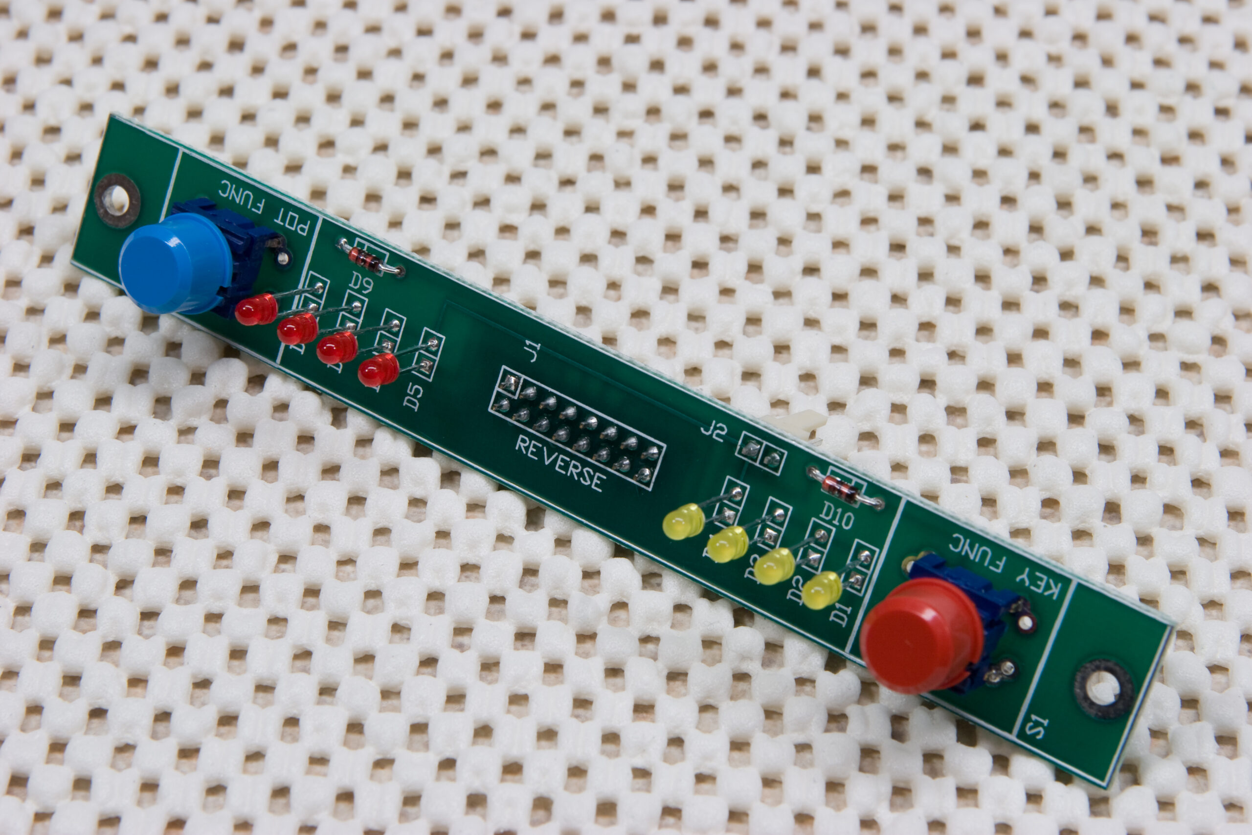
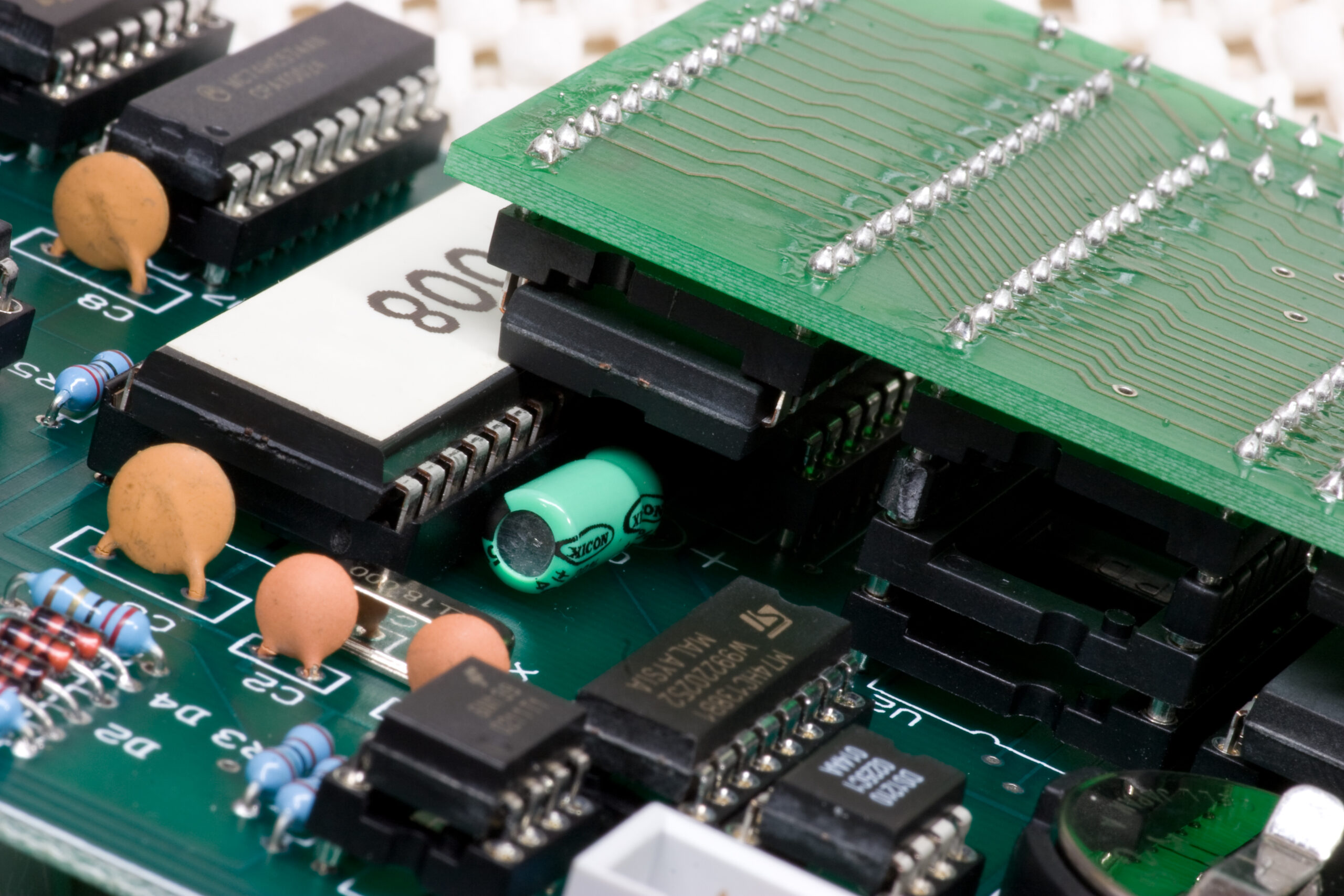
The second problem was that I put the 1N4148 diode on the pot function switch backwards. You can see the error here. The misplaced part is D9. This caused the button not to work and was real easy to troubleshoot.
I also found that the DIN5 MIDI ports on the back of the enclosure sit too low, making plugging and unplugging cables difficult, if they can even reach. Putting an extra M4 nut on each post beneath the PCB raises it up enough, but shorts me on M4 nuts. I’ll see if I can get some more tomorrow.
Upgrading the firmware to the v4.00 beta 26 to support the MemX memory expansion module was a bit of a hassle, simply because I kept receiving a BAD DATA error every time I tried. I originally thought the problem was due to some MIDI routing weirdness caused by new MIDISPORT drivers or MIDIOX, but in the end it was simply a firmware version compatability issue. This was resolved by using a bootloader update found in the analogue-sequencer file section.
After getting to the v4 firmware I ran into two other problems. First, capacitor C3 was tall enough and located in such a place on this old version of the PCB that the MemX board simply wouldn’t plug in. This was resolved by replacing C3 with a new 10μF 25V electrolytic cap, but mounting it on its side to be lower profile.
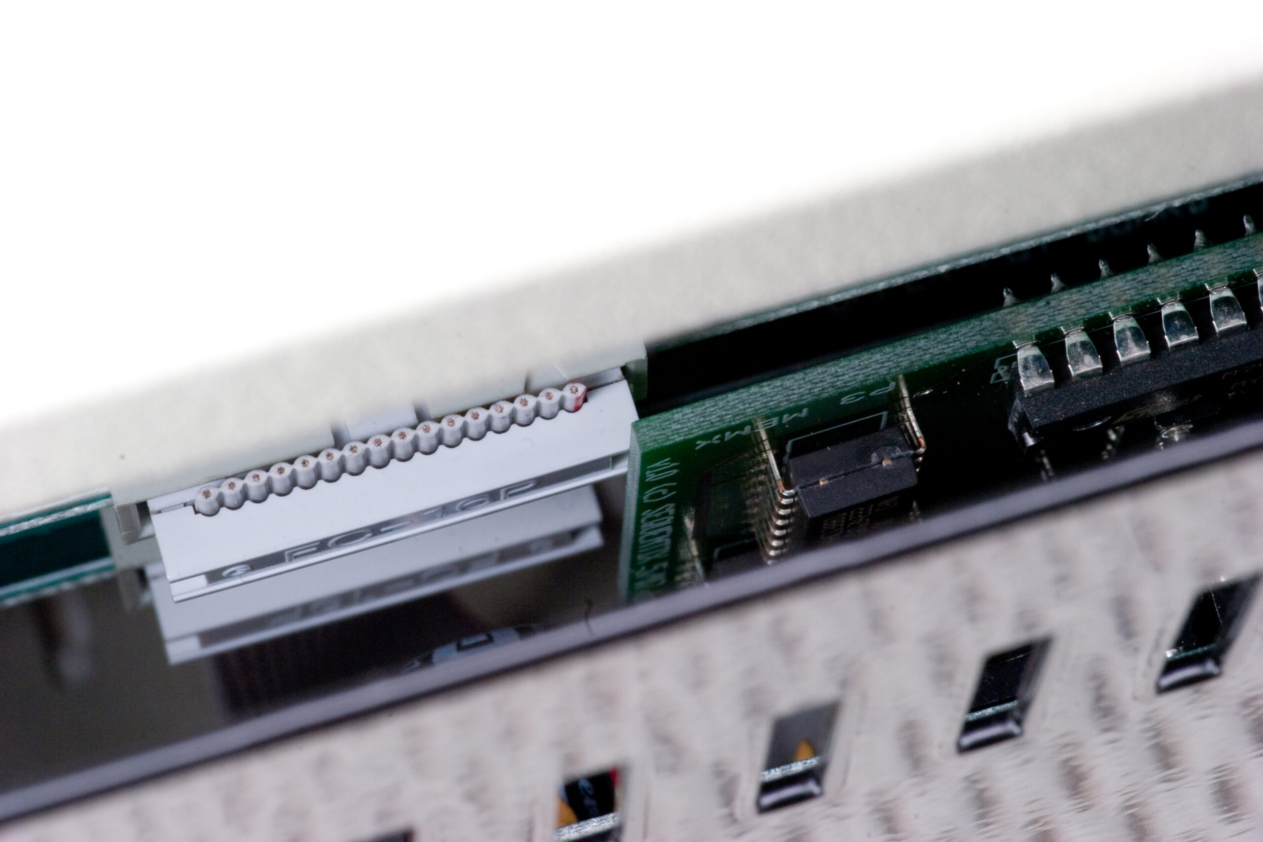
Then, while putting it all back together, I ran into what’s probably the biggest actual problem of the whole assembly: the case won’t close with the MemX board fitted. The place where the MemX board sits in the enclosure just happens to be directly below an IDC connector and the pot board. With the MemX fitted the case stays open about 1.5cm. With this large of a gap I can’t move the board sideways to avoid the connector because then it’d just hit another PCB.
As you can see above I was able to finish up the knobs and get the case mostly complete. As soon as I talk with Mark and figure out what he’d like to do with the MemX board (leave it out and sell it, or see if I can find another way to fit it in, which may not be possible) I’ll be ready to finish up testing and ship it out. All the buttons and pots work as expected. The display does its thing, and MIDI in works. I just need to test MIDI out and maybe sequence a couple things with it just to be sure it’s working and it’ll be done and on its way back to Mark.
Per usual, there’s a bunch more photos to look at. The ones taken tonight start on page 3 (photo gallery retired), so help yourself if you’d like to see them.