nuxx.net
Making, baking, and (un-)breaking things in Southeast Michigan.

Category electronics

Yay!

My legs and ass are sore from sitting on a stool for the last five or six hours, but I’ve finished assembling the first batch of the RS232 to Eaton Leonard Level Shifter parts. They still have to be washed and tested, but they look good. Now to go wash the soapy rosin-based flux off my hands and go to sleep. I have a meeting in seven hours.

electronicsmaking thingsmoved from livejournal

Parts! Parts! Parts!

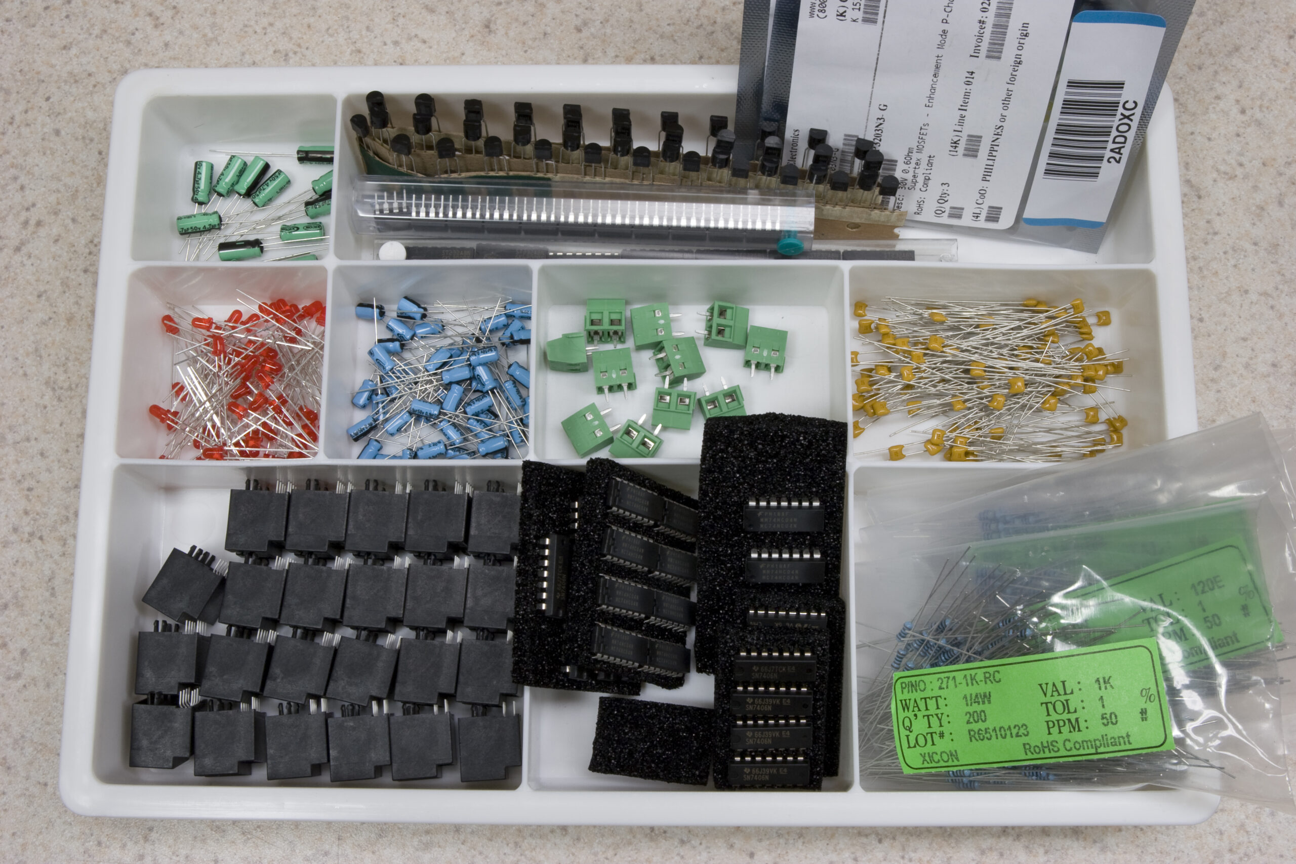
All parts for the assembly of 11 RS232 to Eaton Leonard Level Shifters.
(Click for huuuuge….)

Well, with the Mouser order arriving, I have all the parts for the boards. The Phoenix-branded screw terminals seem to fit the footprint I drew for them, which is a good thing. Now I just need to wait for the boards to arrive. Part of me thinks that I should have spent the extra $30 or so on overnight shipping, but I don’t really think that waiting until Wednesday (when they are slated to arrive) will be a huge deal.

I’m really anxious about it, somewhat worrying that I screwed up something else in the design and that it won’t work. <frets>

We’ll see. :)

electronicsmaking thingsmoved from livejournal

Eagle3D

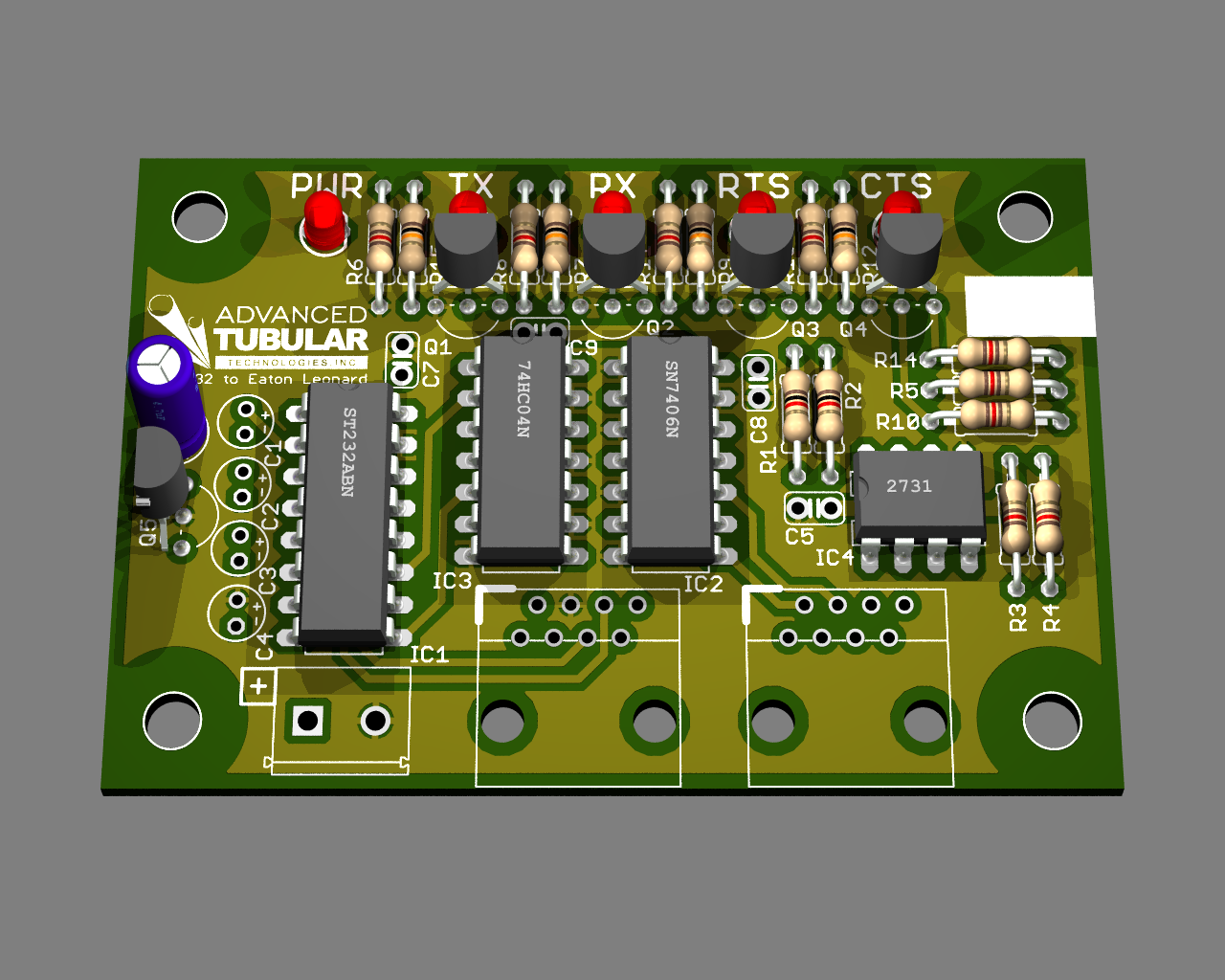
Second-Try Render from Eagle3D

A bit bored at work today I’m poking around with Eagle3D which generates POVray files from CadSoft Eagle .brd files. The ceramic disc caps up there are wrong caps are mostly missing, the TO-92 parts are misaligned, and the screw terminals and RJ45 connectors are missing, but I think it looks pretty nifty.

At this point I’m going to stop messing with it and get some lunch. I don’t need an accurate rendering of the board for anything, I just thought it was nifty to mess with. Now to figure out some lunch… I’m not sure what I’m going to have, but it’ll probably be something low cost.

computerselectronicsmoved from livejournal

RoHS, here we come!

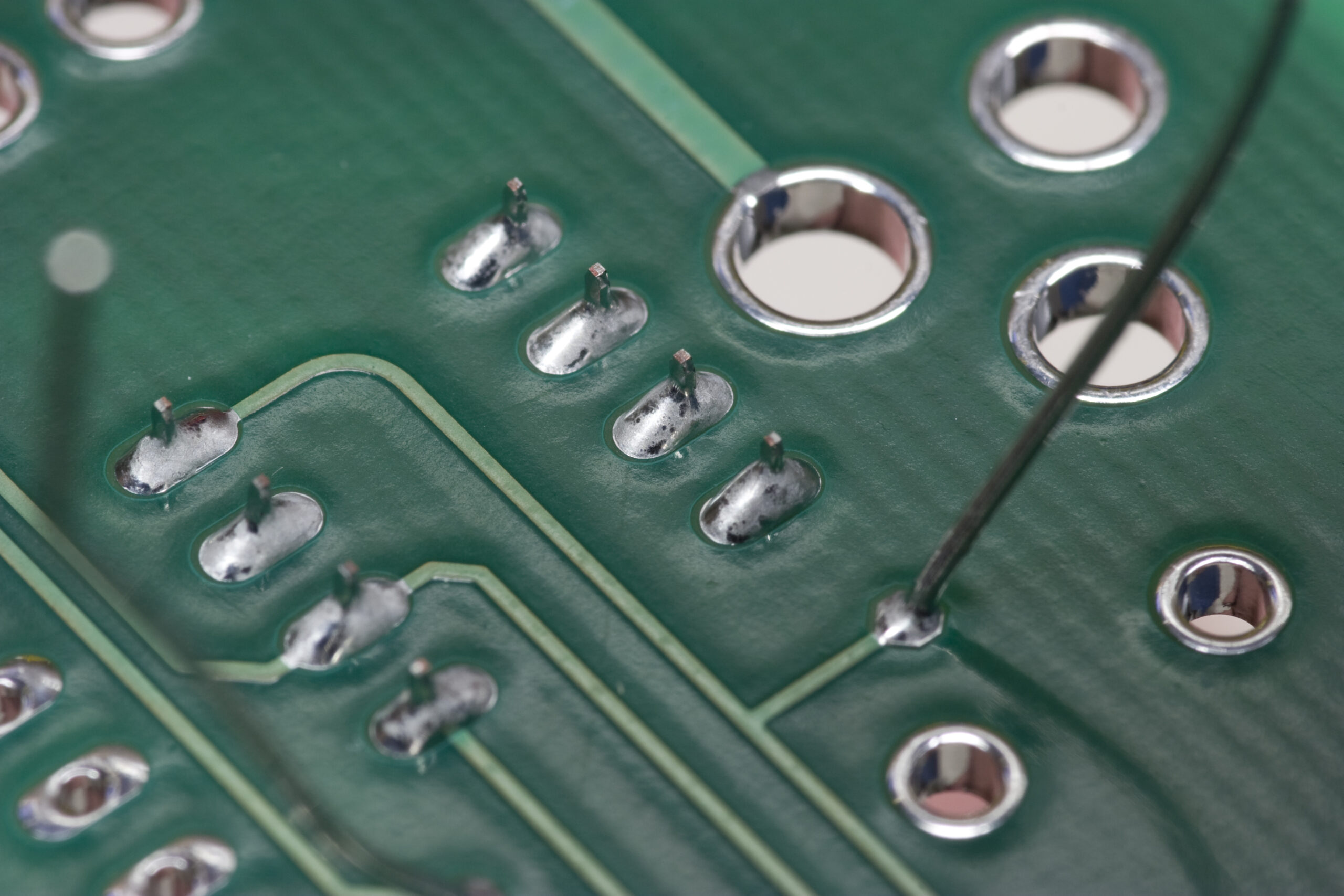
Lead-Free test of 555 Timer and Resistor
(Click for full res…)

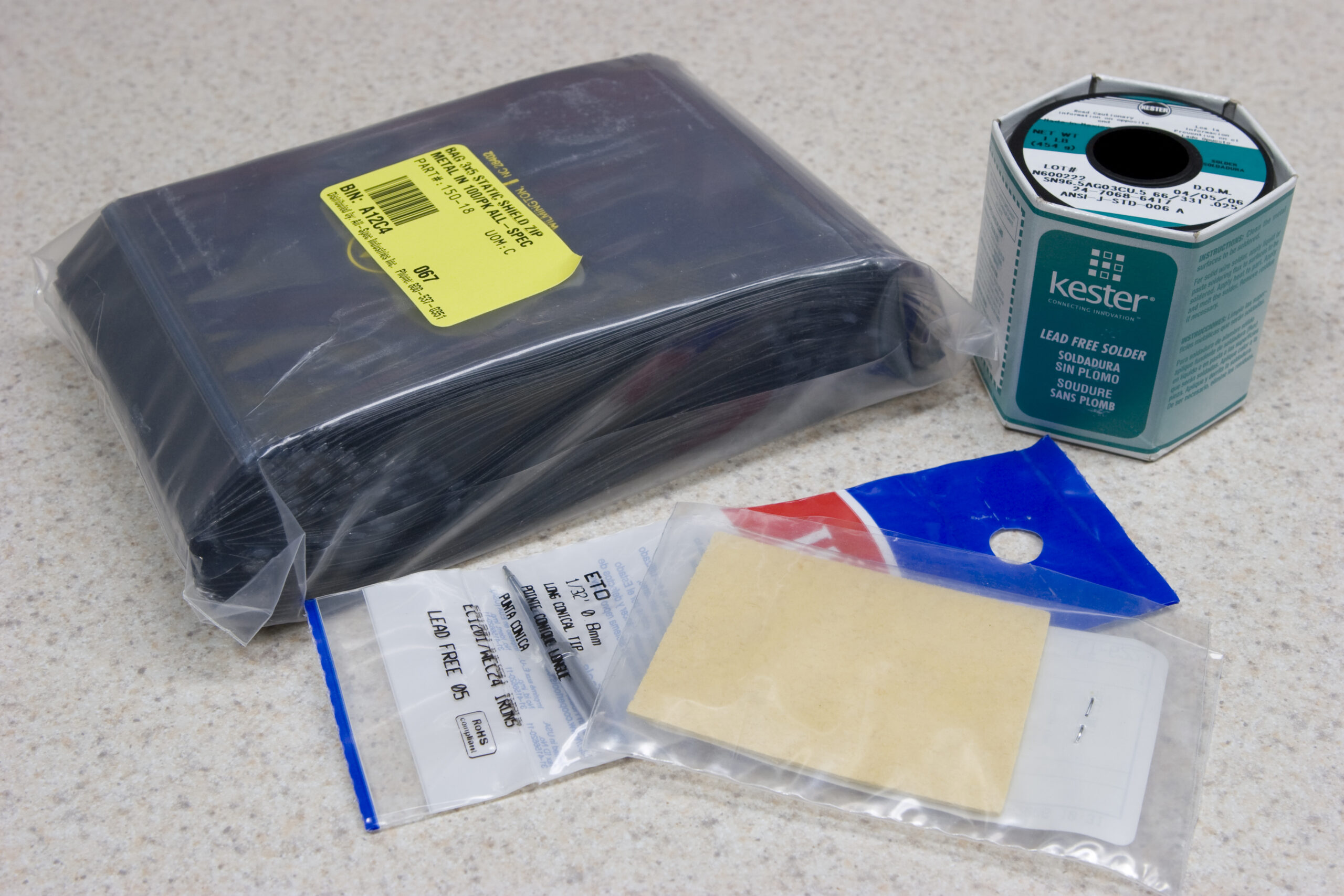
Today my order of lead-free solder and anti-static bags arrived. That meant that was finally able to stick the new ETO tip on my iron, get out the new sponge, and set everything up for trying out lead-free (SAC: 96.5% Tin, 3% Silver, 0.5% Copper) soldering. To get started I acquired a spool of 0.025″ Kester SAC solder with 331 (water soluable) flux.

I must say, this is quite different… First off, I had to turn the temperature up to 750°F. Then, after that, it was rather like soldering with the low-flux no-clean lead solder. The joints don’t wet as much, flux still flows but it doesn’t seem to help as much, and the resulting joints just aren’t shiny. All of this is in line with what I’d read about lead free solder, so that’s at least good.

The flux came off nicely with a toothbrush and hot tap water (my normal process, followed by a rinse in distilled water and drying with an air compressor) so I’m quite happy with that.

After reading this article from Kester (PDF) I may give an 800°F tip a try next time, but for now I’m pretty happy with how things were coming out.

A few more photos of test joints, both before and after flux removal, are available here (photo gallery retired).

electronicsmaking thingsmoved from livejournal

Boards Ordered, etc.


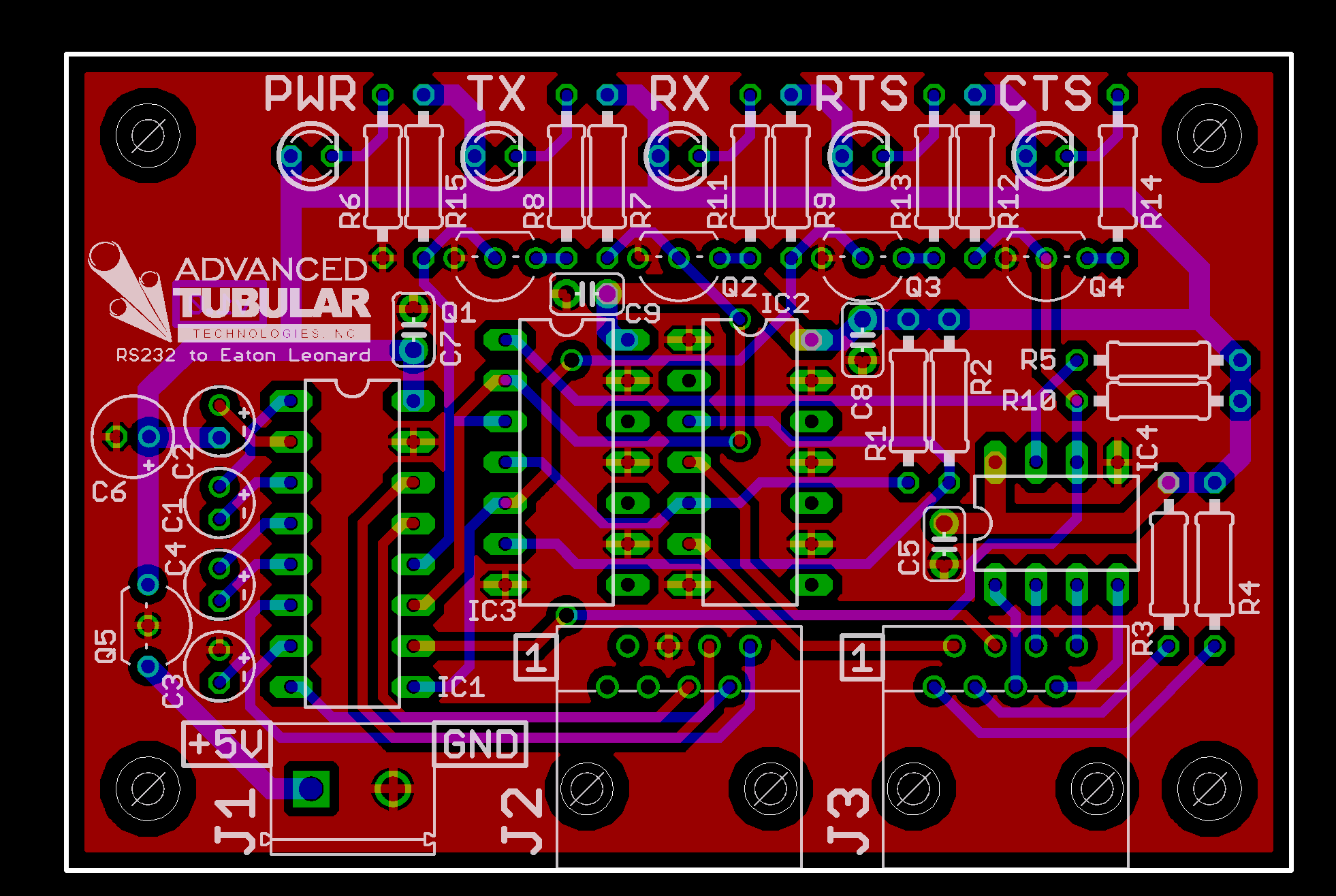
Final v1.0 Board
(Click for 600dpi version…)

Well, it’s done. I’ve ordered the first run of boards, all the parts needed to make 11 pieces, lead-free solder, static shielding bags, etc.

The biggest difference between the previously posted version and this one is I had to squeeze in four more resistors (pull-ups for the lines going to and from the MAX232), but that wasn’t too difficult to do.

Now it’s time for Danielle and I to go get food and see a movie.

electronicsmoved from livejournalwork

RS232 to Eaton Leonard Interface Final?


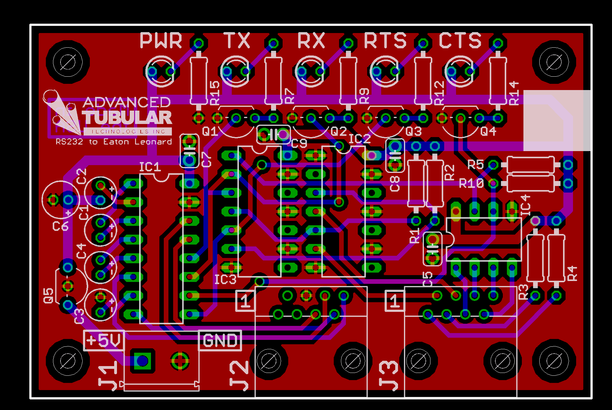
Third Draft of RS232 to Eaton Leonard Layout
(Click for 600dpi version…)

Well, I think it is done. As long as the schematic passes the final validation (which I’ll do tomorrow) that up there will be the final version of the RS232 to Eaton Leonard level shifter board I’ve been working on for ‘ company. It’s only 2″ x 3″, down from the original 4″ x 4.5″ part.

I’ve also made the following changes from the original design:

· RJ45 connectors for RS232 and the connection to the machine itself.
· +5V supply, as opposed to the original board needing +15/-15/+5.
· Greatly decreased size.
· RoHS compliance.
· Protection against power being connected backwards.
· Power / TX / RX / RTS / CTS LEDs.
· Greatly decreased cost.
· Branded.

Hopefully I’ll order the boards and all other parts I need for the initial production run either tomorrow or Monday. I just need to catalog the parts I have, order the rest of the parts, order the boards, order the lead-free solder, packaging materials, etc.

Now, off to National Coney Island, REI, and the Apple store with Danielle.

electronicsmoved from livejournalwork

Electrical Design Complete

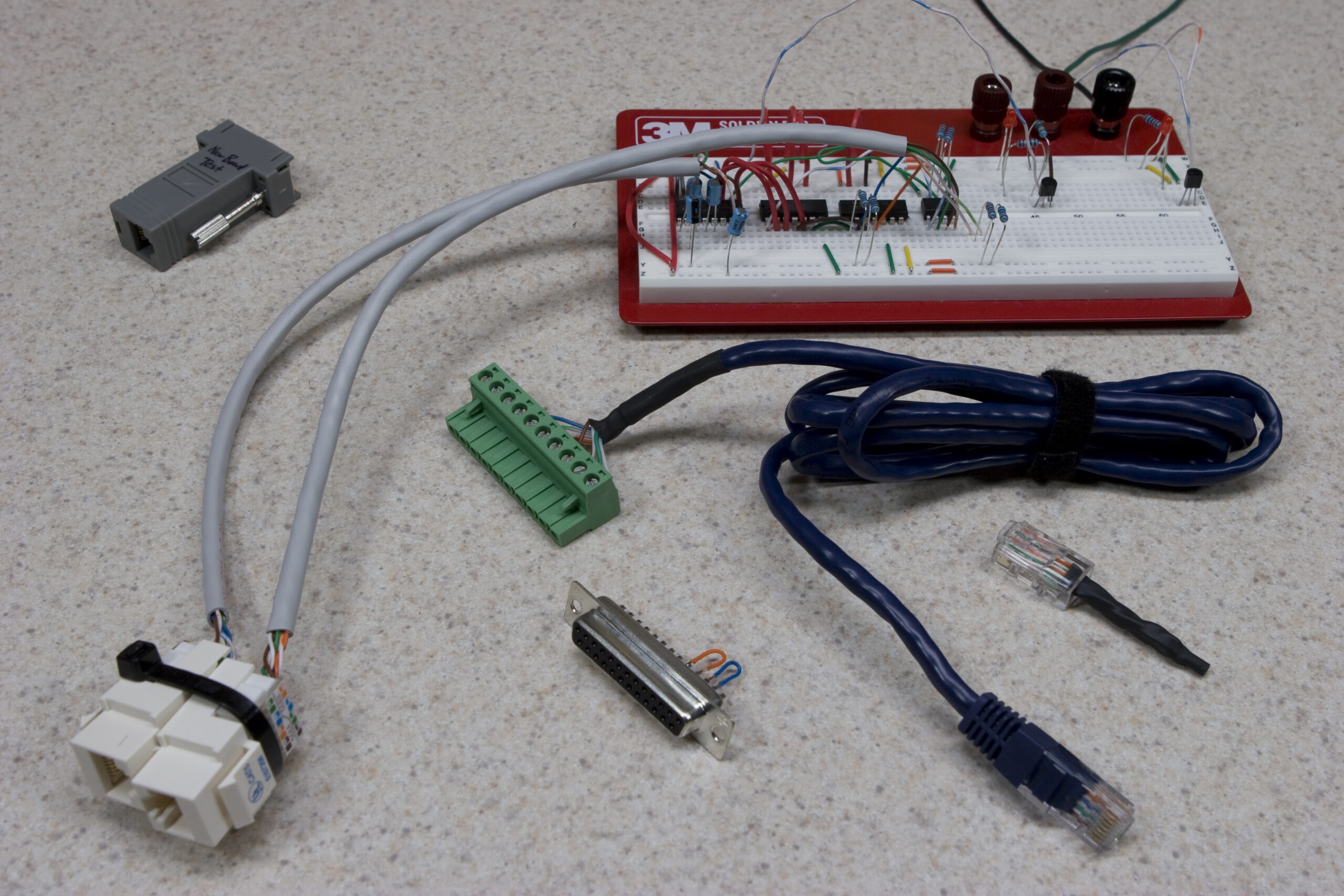
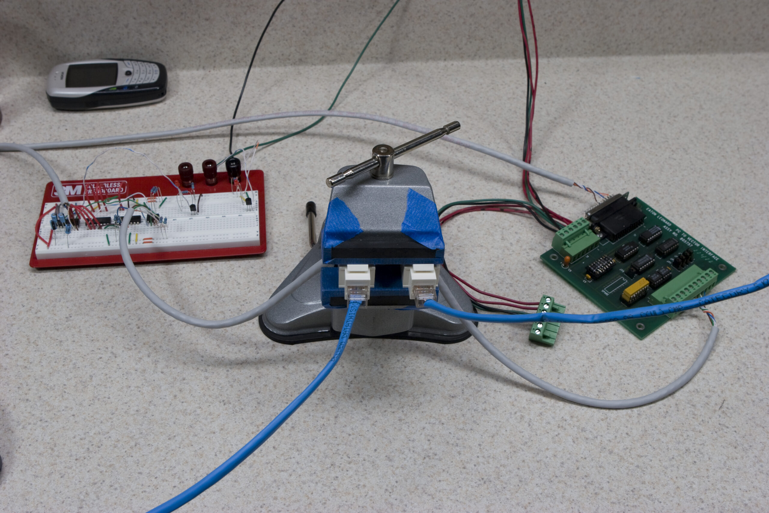
Breadboard circuit and some adapters.
(Click for more photos of this project (photo gallery retired)…)

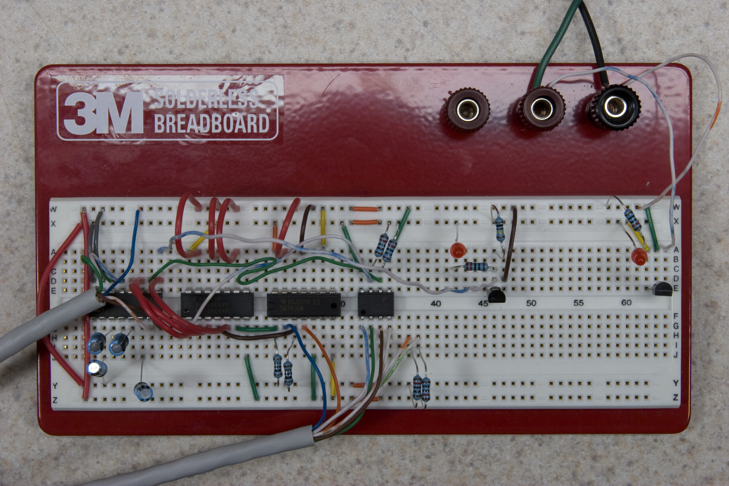
Well, there it is. The final breadboarding of the RS232 to Eaton Leonard Level Shifter that I’ve been working on. On the breadboard there is the complete circuit, including current reversal protection, but with only one of the indicator LEDs. I ended up changing to using BC557 transistors for turning the LEDs on and off, because the FETs I was originally looking at were leaking current through even when off. I only had one BC557 here, so I just put together one of the circuits and then tried it on each of the lines. It seems to work fine, blinking with data, etc. Its activity should match that which one would see on a PC if using software TX/RX/RTS/CTS activity indicators.

I also played around with sending data through my board to an original Eaton Leonard one, and over a short cable run I had no retries when sending a DOS 6.22 install floppy image at 19.2k via ZMODEM between two HyperTerminal sessions. Since the actual device in production will run somewhere around 3100 baud, this should be good.

I made adapters so that I can easily plug a piece of CAT5 of arbitrary length between the two boards, so I can try to intentionally create unfavorable conditions. Some initial testing stringing an old piece of CAT5 around three fluorescent lamps didn’t show any immediate errors. I’ll do more in-depth testing with this setup over the weekend.

Finally, here is a photo of the stuffed breadboard itself, as I tested it. Now all I have to do is verify the footprints of all the parts I’m using and lay out the PCB. Doing that is fun, and kinda easy. Then it’ll be production time.

electronicsmaking thingsmoved from livejournal

Good Things

The following things are good:

· My board works, sending and receiving data. The problem was some stupidness, easily corrected on the breadboard.
· Tobi is, thus far, being a joy to have around. She likes playing both with her reflection in the doorwall and a Kong.
· Celebratory Kentucky Breakfast Stout
· The circuit to keep things from being fried of current is hooked up backwards works great. The FET only causes a 0.010V (measured) loss.

Tomorrow I will add the LEDs which indicate the activity of each line and be sure they work. I’ll also incorporate the current reversal bits to see how it all plays together. Then I’ll try sending large quantities of data through at high speeds (115,200), possibly even across a lengthy run of CAT5 in a noisy environment. I’ve already done short bursts of characters, but I’ll try sending 10s of MBs of files or something.

If that all works, I will begin designing the final PCB over the weekend. Yay!

electronicsfamilymoved from livejournal

Worky worky worky…

After feeling kinda crappy about my current project last night I ended up going to bed and laying there for a while thinking about things. As a result of talking to a friend online about some electronics stuffs, I decided this is what I need to do:

Breadboard the whole damn thing, so that changes and new features are easy to implement, and I can work around the inverted data problem more easily. It really is the “proper” way, as opposed to what I did before: come up with what I think should work and spend time hand-etching a PCB.

So, today I went ahead and ordered a batch of new parts, including some I’ll need for assembling the final boards, some I want to try (different FETs, dual optoisolator) instead of the current design, and a few other things. When the parts arrive I’ll breadboard it all, get it working, ensure that my schematic matches, then order the prototype boards.

That same friend also helped me out a bit with the use of FETs for current reversal protection, triggering LEDs, and a few other things. That was really, really helpful.

Advanced Circuits credits one back the price of bare-bones prototype PCBs (no soldermask or silkscreen) when production boards are ordered, so this should work out well. I also won’t have to deal with etching a board by hand.

electronicsmaking thingsmoved from livejournal

Making Stuff

I’m feeling amazingly frustrated with the project I’m working on.

I think I know why the data coming in isn’t working, but the data going out has suddenly stopped working coming out corrupt (test is received as QsT.), and I really don’t know why.

I’m considering taking a bit of a break from it, or maybe stepping way back and taking a wholly different look at it, what it does, and how I could do it better, end to end.

The problems all seem to stem from what a hack the board itself is that I’m trying to clone. Maybe I shouldn’t try to keep approximately one half of it original.

electronicsmoved from livejournalwork