nuxx.net
Making, baking, and (un-)breaking things in Southeast Michigan.

Category: making things

iPod in 2006 Civic Update, Part: Whatever


Finished custom Aux In connector. (Click for more…)

Well, a bit more progress was made on the iPod connection for my car. Today I soldered up the Aux In connector, potted it in epoxy for strength, shrink tubed it, soldered a 3.5mm (1/8″) connector on the other end for testing purposes, and tested it out. And guess what? It works just as designed.

The connector fits into the factory connector perfectly, tells the Navigation Unit (head unit) that there is something connected to Aux In, and accepts audio in phase on the proper channels.

Also, while cutting the black TuneDok stem to fit, it seems that I squeezed everything so hard that it caused oil to be squeezed out of the vinyl. Wow.

So, yeah. Both the spacer and heads of the bolts are painted, and I’m just waiting for the aluminum plates to dry so I can photograph them. I did get this really nifty photo of wet paint on one of the aluminum washers which I think could do nicely as a flyer photo or something. Well, provided the flyer was printed fairly nicely.

Now all I need to do is order the rest of the parts I need. These should include a cast aluminum project box, PCB etching kit, tin coating kit, and a few other odds and ends which I need to finish everything up. I’ll go order those now, I think.

automotiveelectronicsmaking thingsmoved from livejournal

Honda ‘Auxiliary Jack Assembly’ Connector


Connector for ‘Auxiliary Jack Assembly’ on Honda Wiring Harness
(Click for more…)

Ahh, I think I finally figured out exactly how I would make the connector for inside the dashboard of my car for inputting audio into the connector which originally plugged into the rear of the Aux In connector on my dashboard.

What I ended up doing was taking a PCB salvaged from a 2x CD-R and an old CD-ROM drive controller and pulling the long pins off of the CD-R’s PCB and the plastic .100″ spacer from the CD-ROM controller. I then straightened the pins and assembled the pins into the connector, first bridging pins 1 and 2. (This indicated to the head unit on Honda cars that there is something connected to the auxiliary input.)

I then fit everything into a random (probably the VESA connector) header on an old video card and ensured that there is 3/8″ of pin hanging out the non-wiring side of the spacer. After getting everything aligned, I applied a bit of epoxy to the back (wire) side of the spacer to hold the pins in place.

So, tomorrow, likely after the epoxy has cured, I’m going to cannibalize another MIDI cable for it’s nicely made wire assembly, and I’ll use the red / white / green wires and connect them to the left / right / return (ground) pins on the newly made connector. Then I’m going to attempt to pot the entire solder/wire portion of assembly in epoxy. This will provide a nice bunch of strain relief along with ensuring that nothing in this connector shorts out.

Even though I only need three pins, I think I’ll use a DB9 connector for the other end, the one which will connect to the junction box. It’ll be shielded, easy to solder, unlikely to fall out (screws on the connector), and quite solid.

So, yeah… It’s shaping up nicely thus far. Now it’s bed time or something.

automotiveelectronicsmaking thingsmoved from livejournal

Working With Metal


Metal Plates for the iPod Holder
(Click for more…)

Well, I’m getting rather excited about the iPod mount / adapter which I am fitting into my car. did me a huge favor and had some metal parts made up for me. All they needed was a little bit of work and they were ready to use. I simply had to grind out the underside of the top-most ring-shaped piece (can be seen above), drill appropriate holes, file everything smooth, clean it all up with a wire wheel, and it was ready for test fitting.

Well, if you compare today’s test fitting to the Jenga-like one from earlier in the week it’s pretty obvious that this new solution with the aluminum plates are a great deal better. Sunday or Monday I’ll finish it up by trimming the dark gray stem from the black TuneDok, taking it all apart, and painting the plates, spacers, and bolt headers. Hopefully that’ll go well, too.

automotivemaking thingsmoved from livejournal

Second Version of iPod Connection in 2006 Honda Civic EX


Click for more…

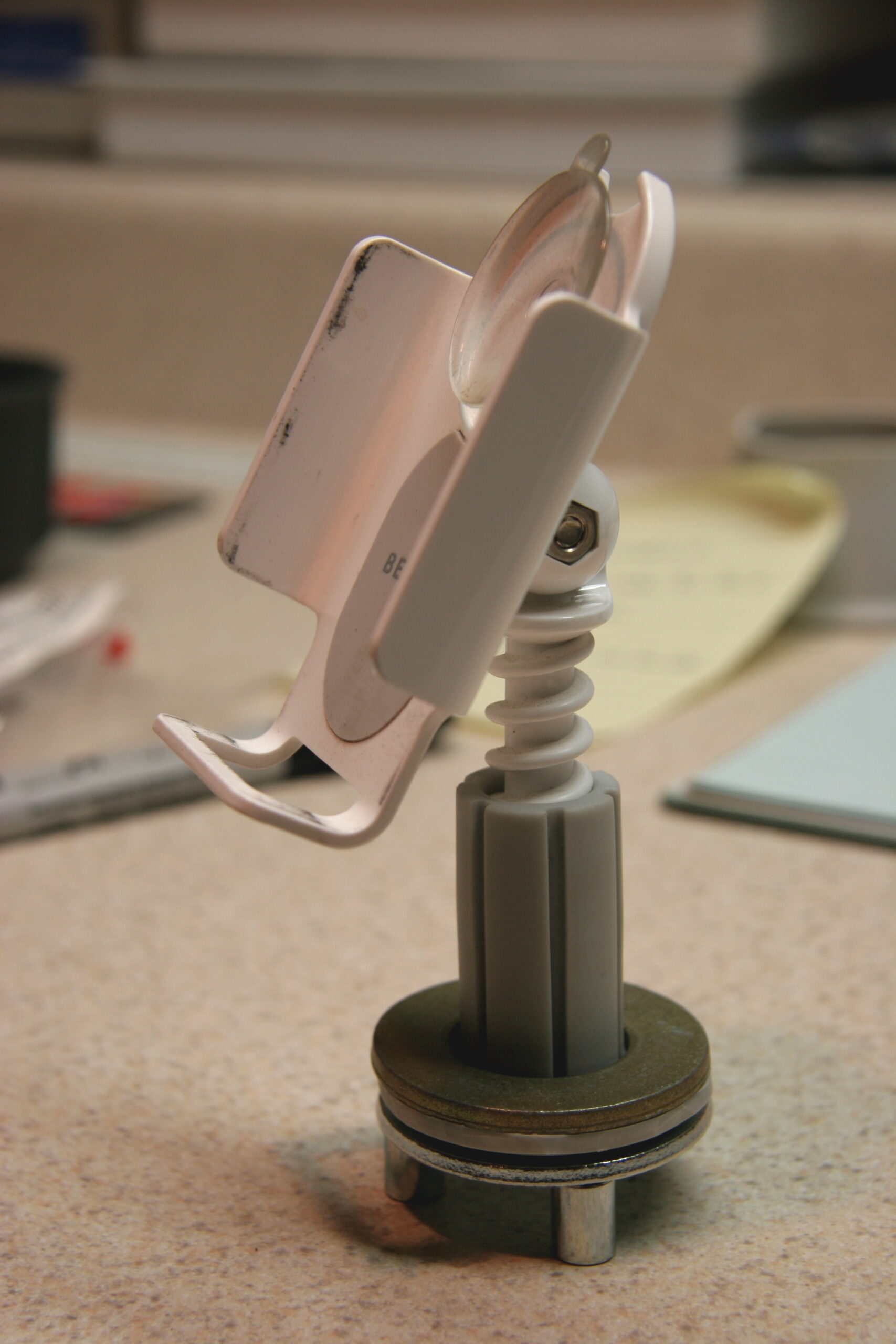
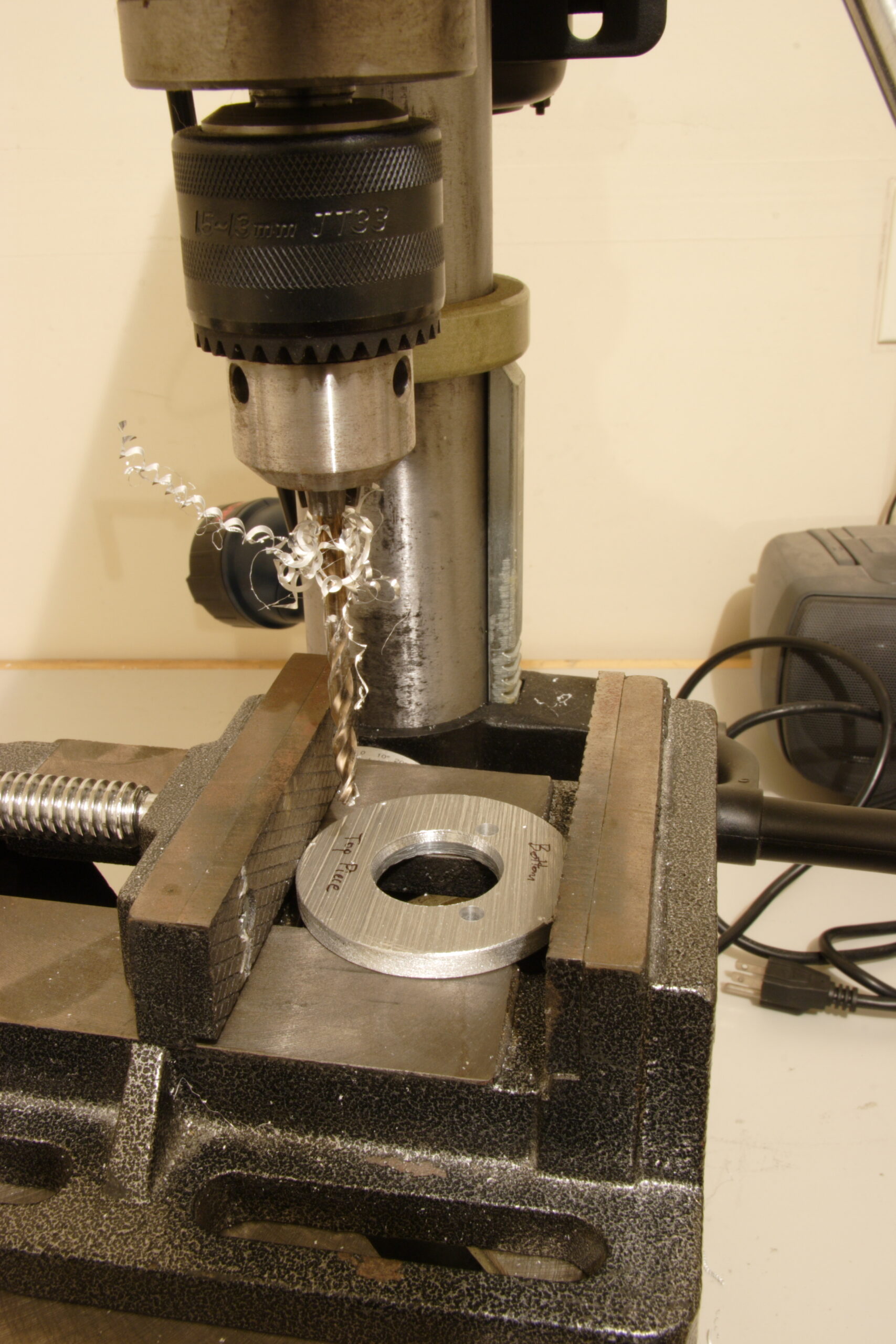
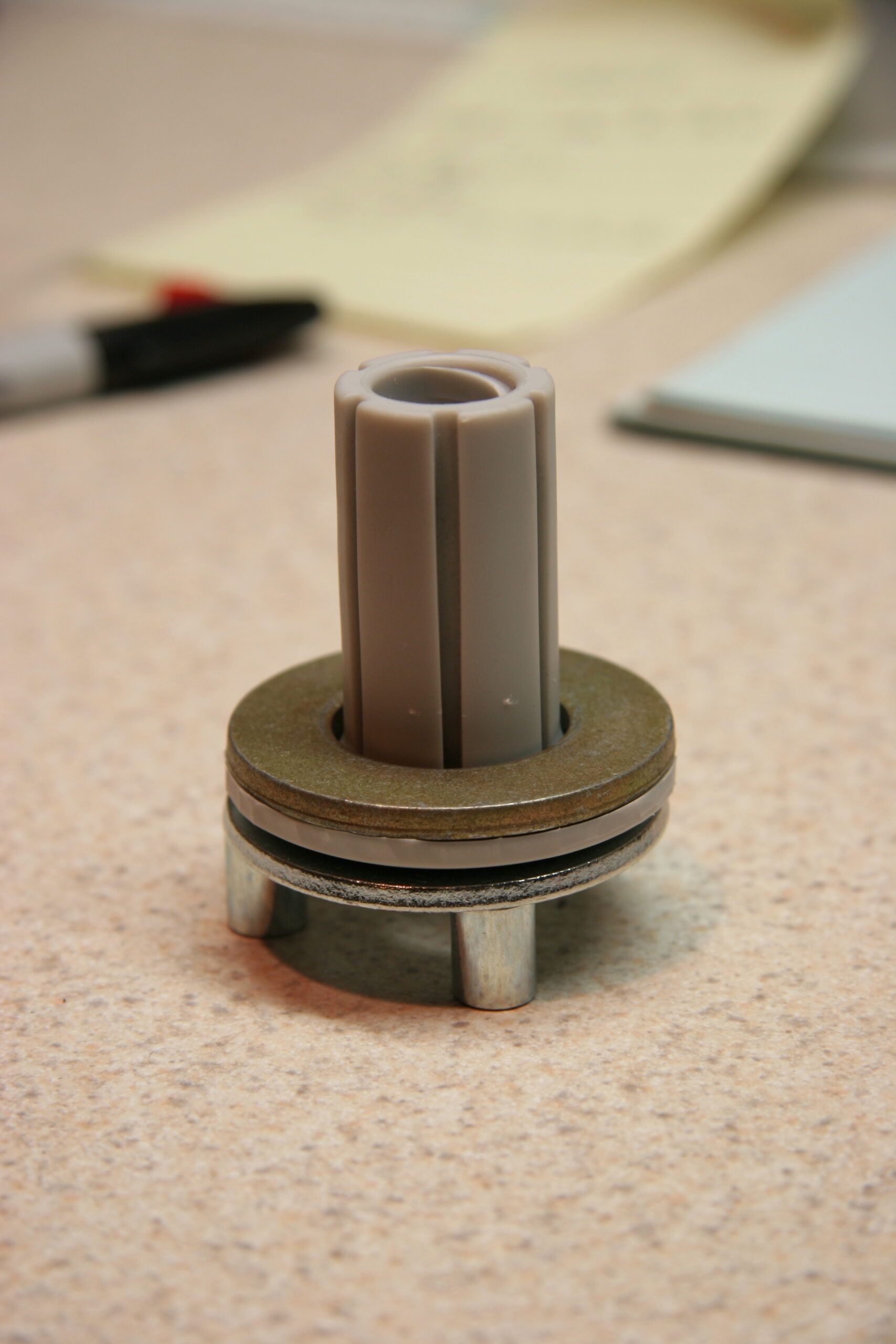
Up there is some of the test pieces I stuck together in order to see if I like how I’m going to mount my iPod in my car.

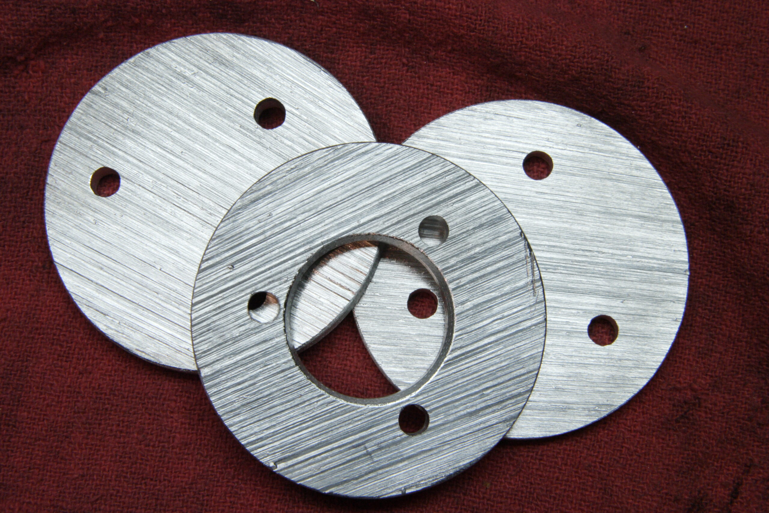
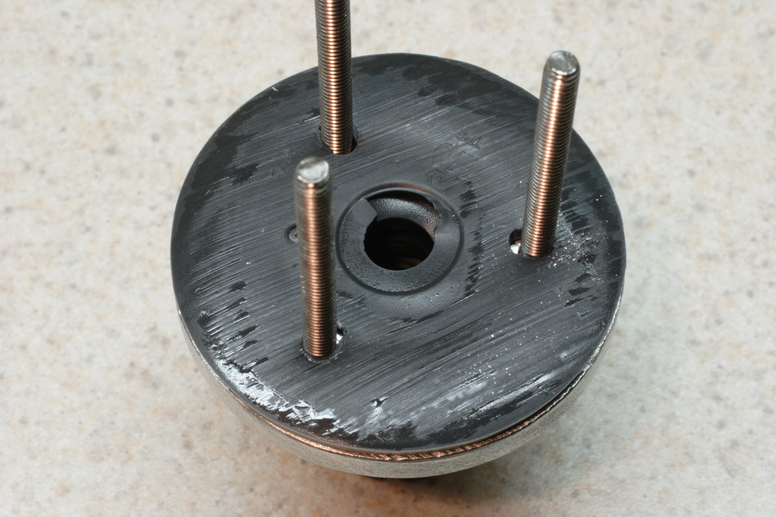
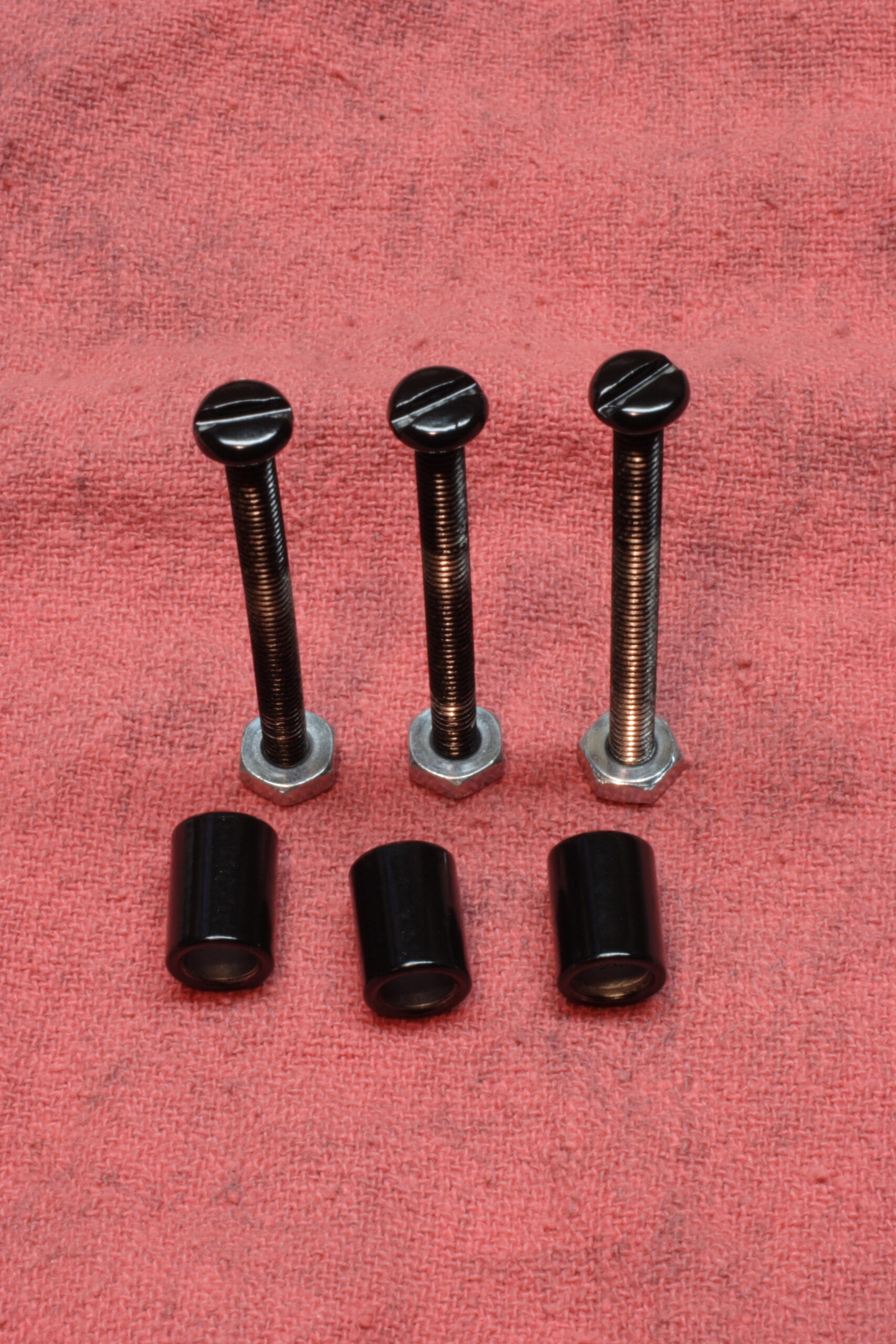
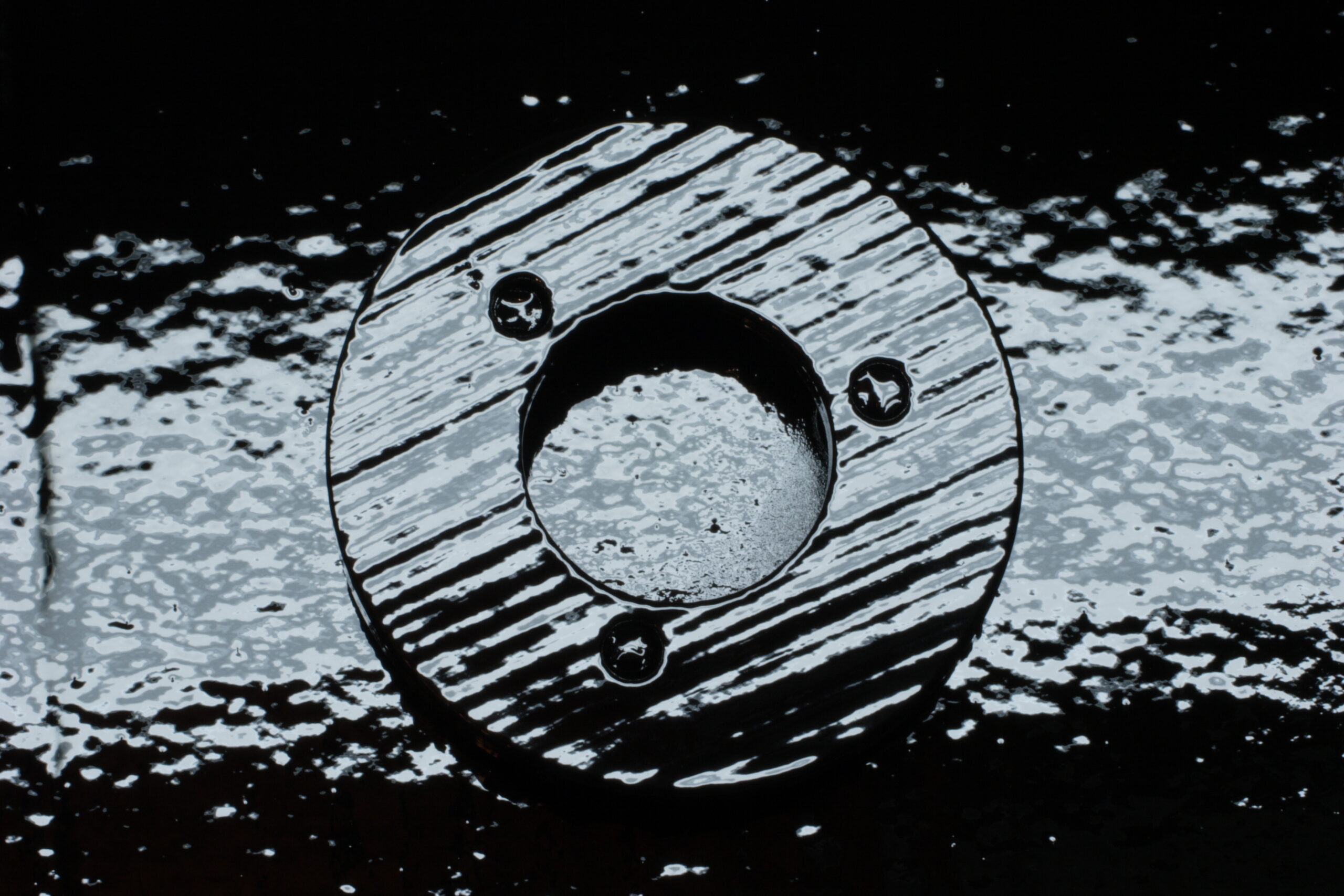
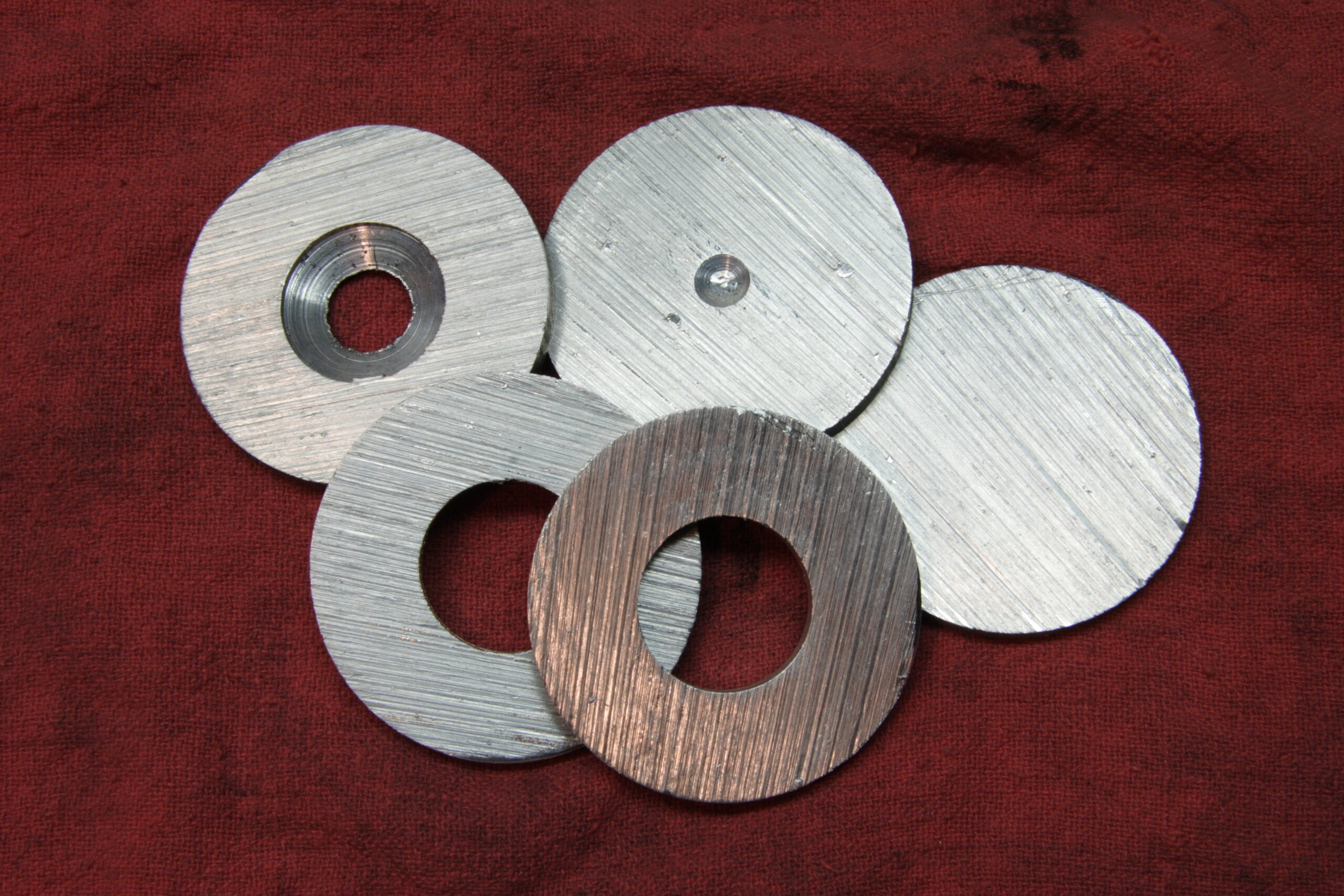
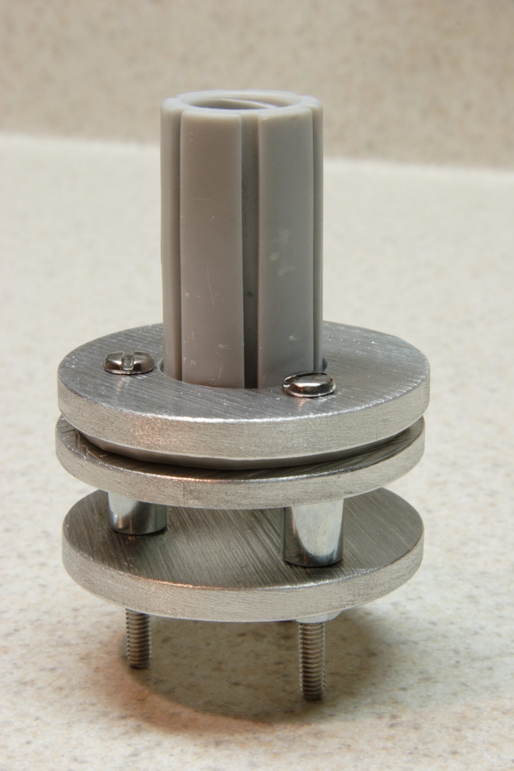
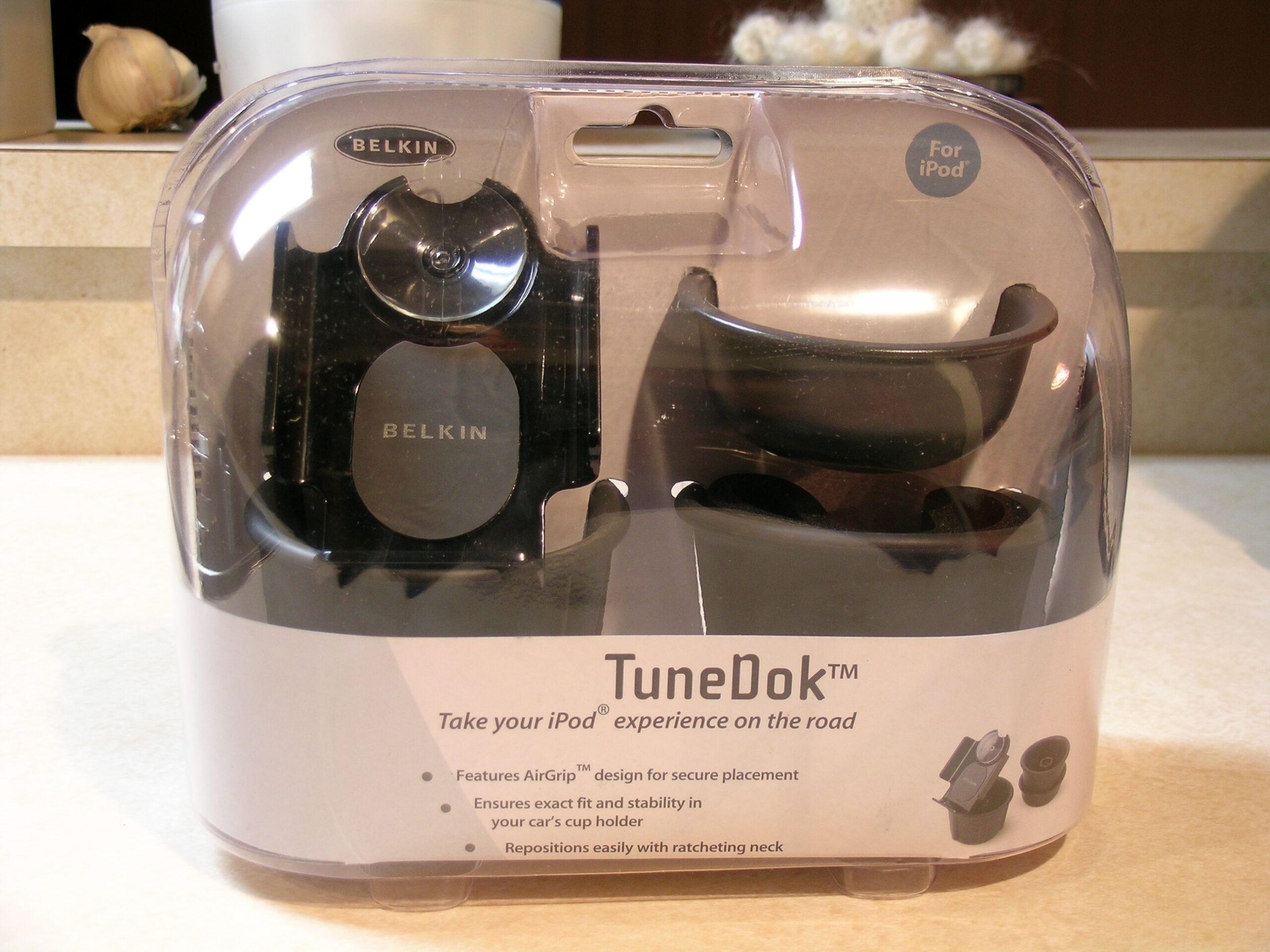
That photo shows a the original grey and white Belkin TuneDok from my Grand Am with most of the cupholder-supporting bits removed. The remaining vinyl bits into which the iPod holder portion threads is sandwiched between two metal plates and set on three spaces. In the final version the plates will (hopefully) be aluminum, there will be a plate on the bottom of the assembly, and that all will be bolted into the very front of the center console of my car, in front of the gear select area, set so the driver can clearly see it between the gear select lever and the accessory power outlet, and located within arm’s reach.

In the finally mounted version I will have most of the bits of a black Belkin TuneDok there instead of the dirty, old white one which is pictured. This will be mounted by running three bolts vertically through all three plates, the vinyl piece (it’ll be a darker grey), and the spacers, then bolting through the plastic tray in the front of the center console, with a washer, a lock washer, and a nut on the underside. I’m also hoping to give all metal pieces (except for maybe the screw heads) a light coating of black paint to help hide it all. If I’m thinking right, it’ll provide a nice, solid physical mounting point for my iPod.

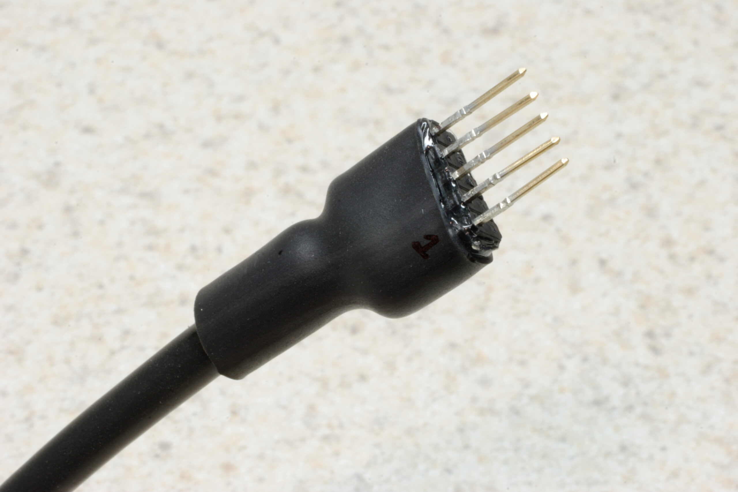
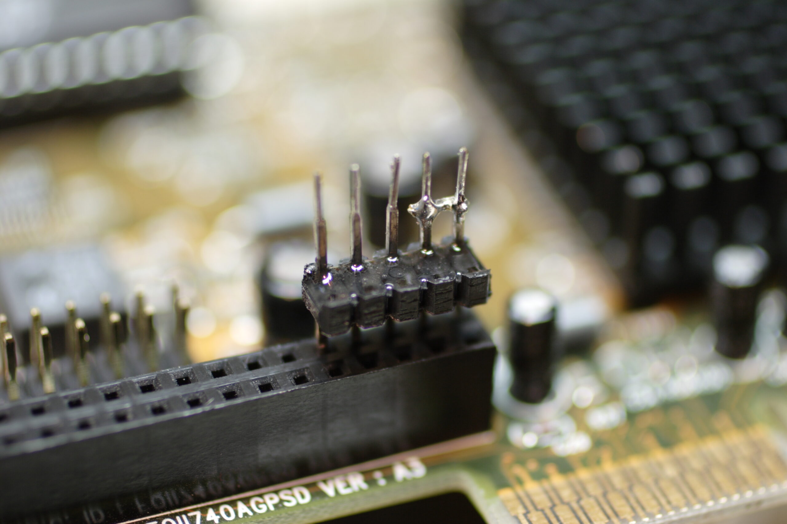
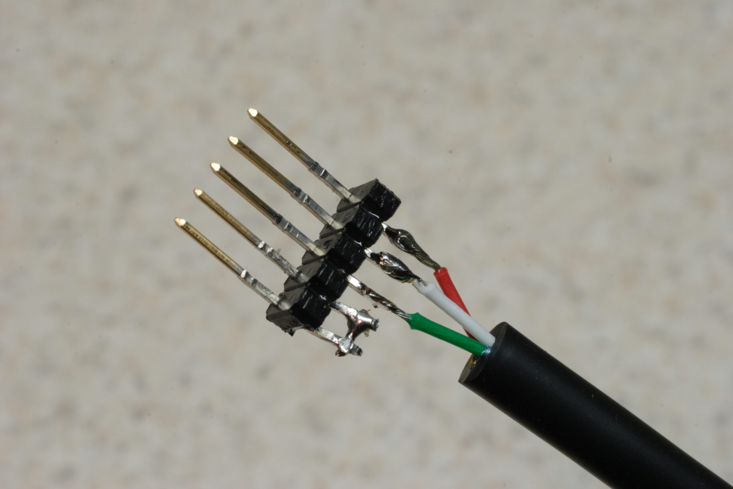
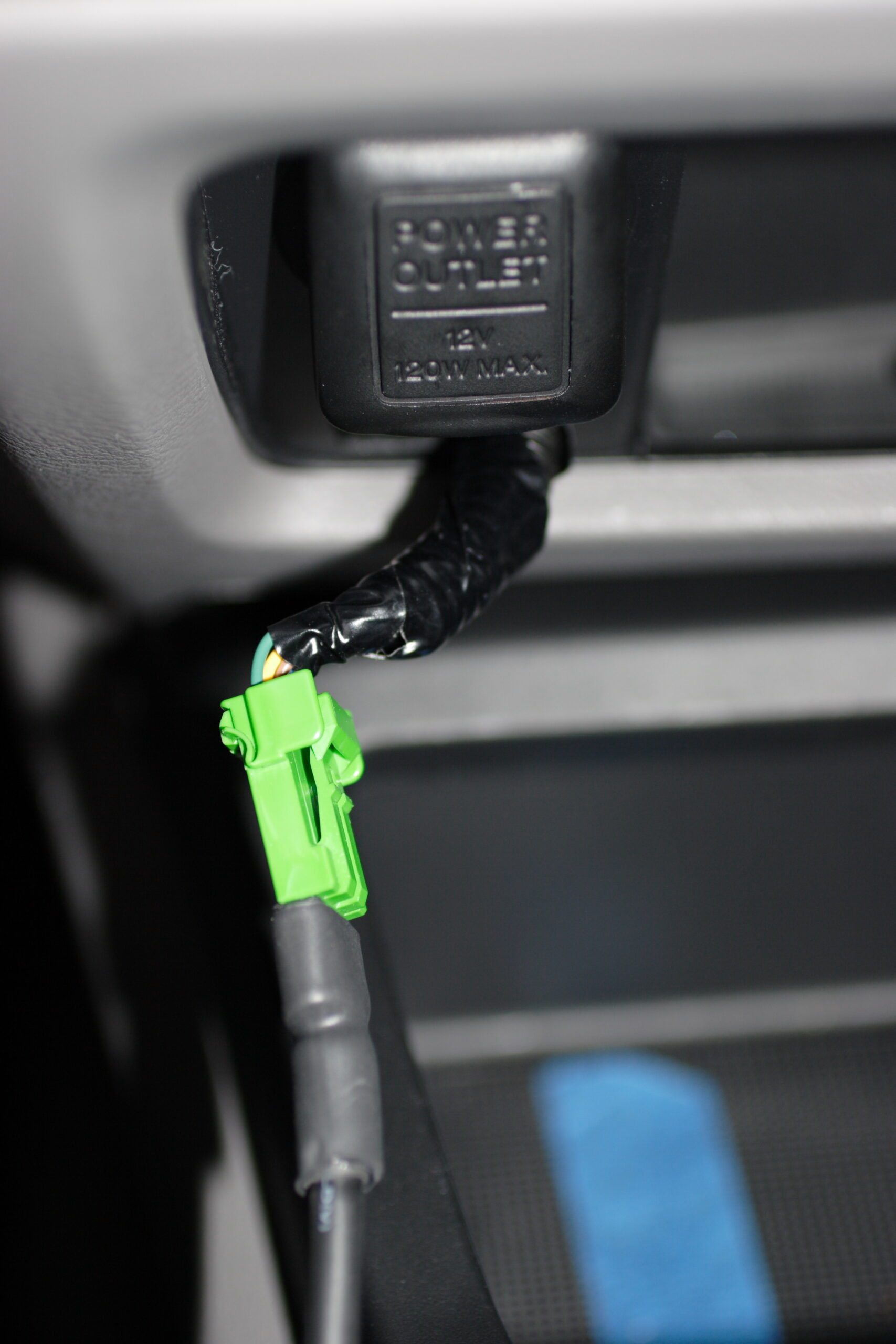
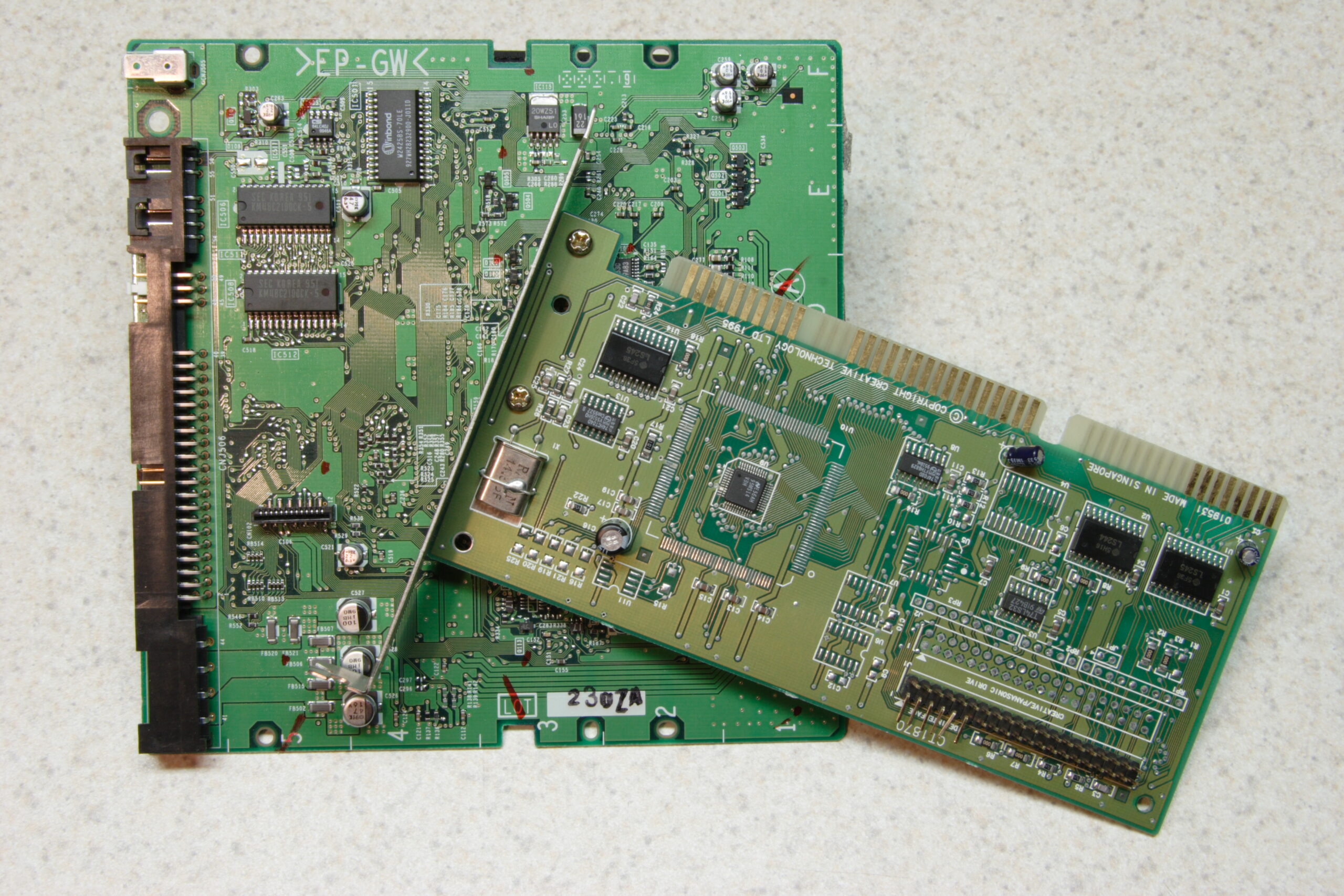
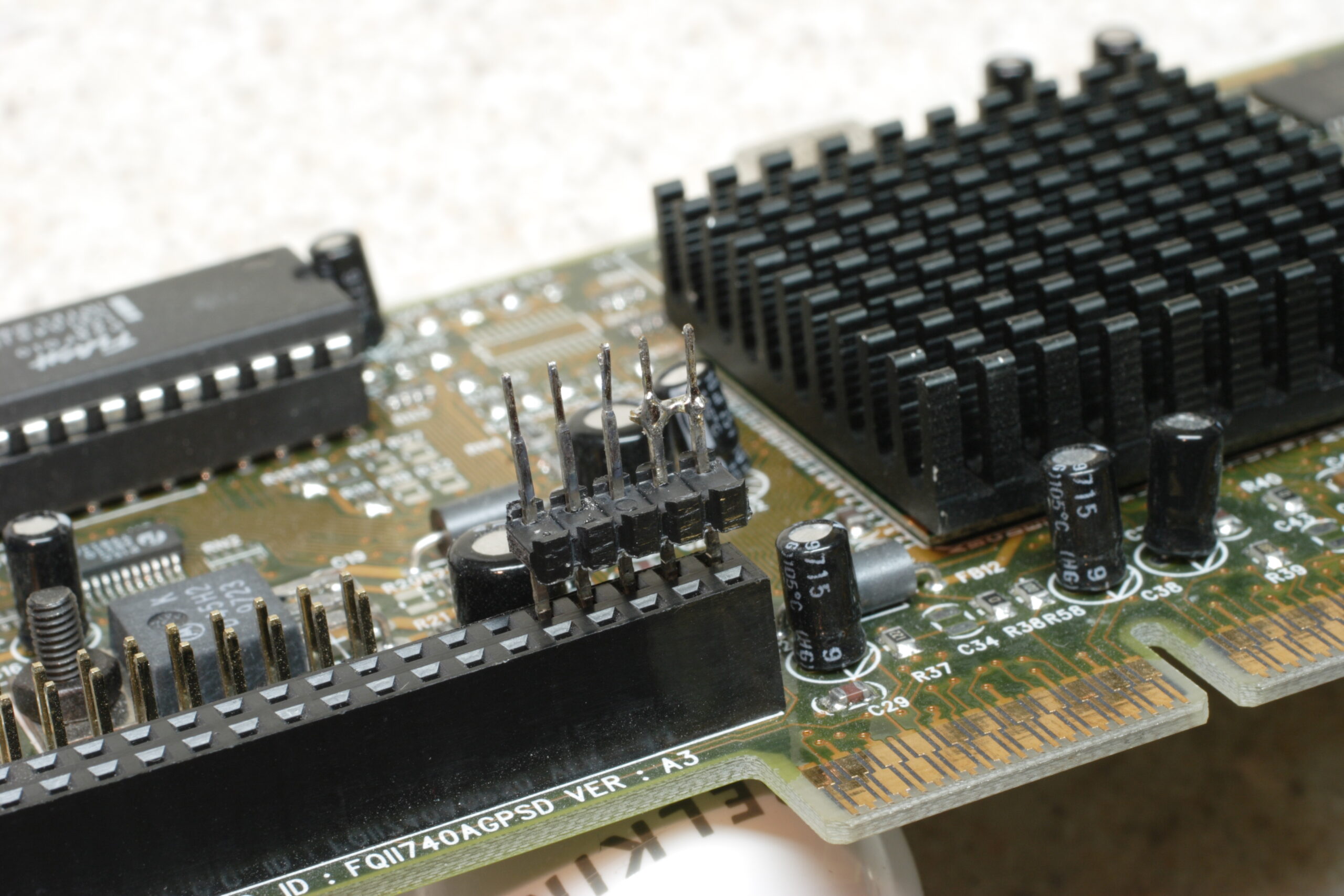
The other half of the problem to solve is that of the electrical connections. Those were mentioned previously, and the only thing I have left to do is find +12v in the audio bus (or whatever it is called) connector on the back of the head unit (I really hope there is a full +12v here) and get access to that. Then I have to somehow safely (and without changing any factory wiring) get to the back of the in-dash Auxiliary Audio Input and get some use out of this. In this I wish to close the switch which indicates if something is hooked up to the Aux In, then run the iPod’s audio into the Left / Right / Common lines.

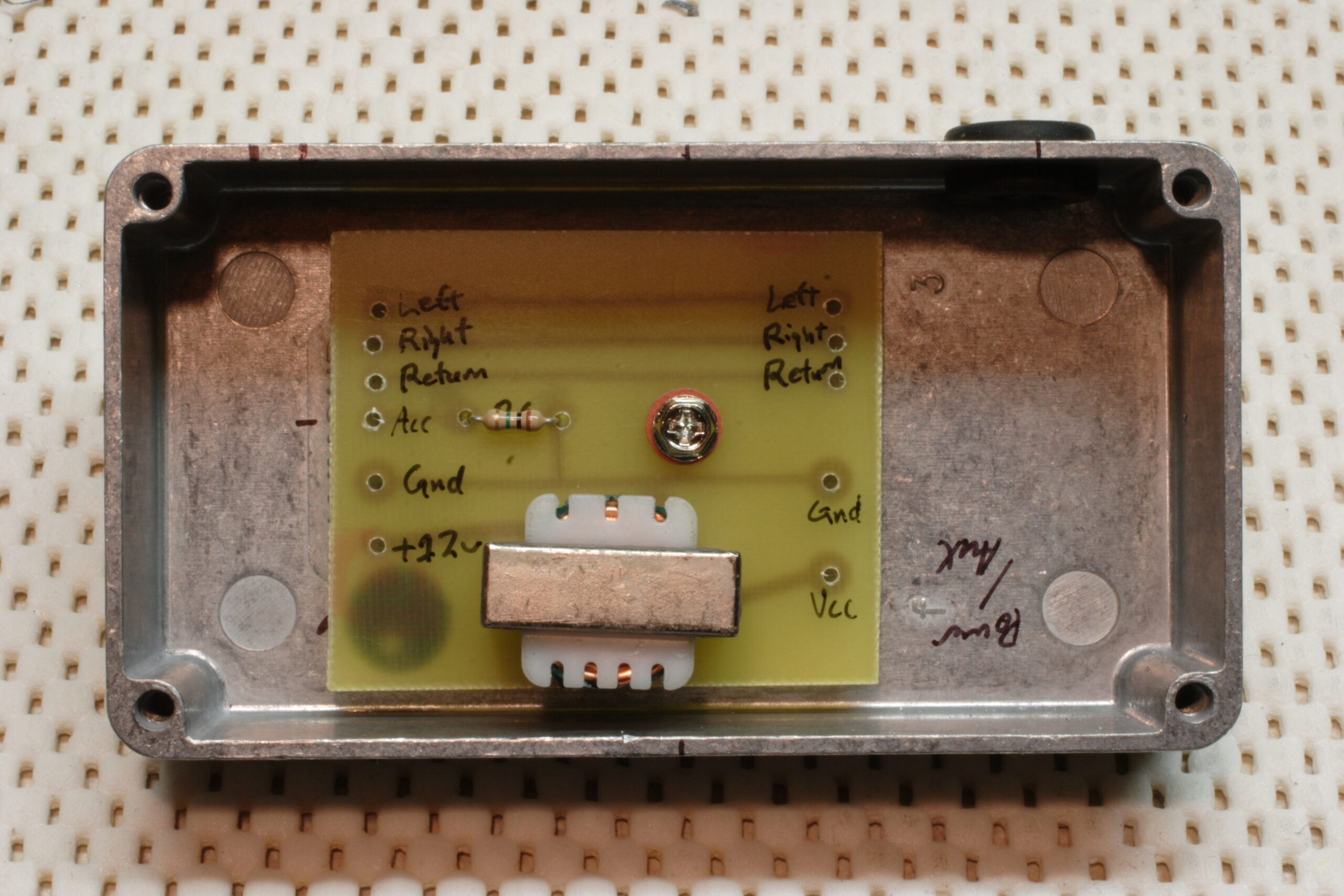
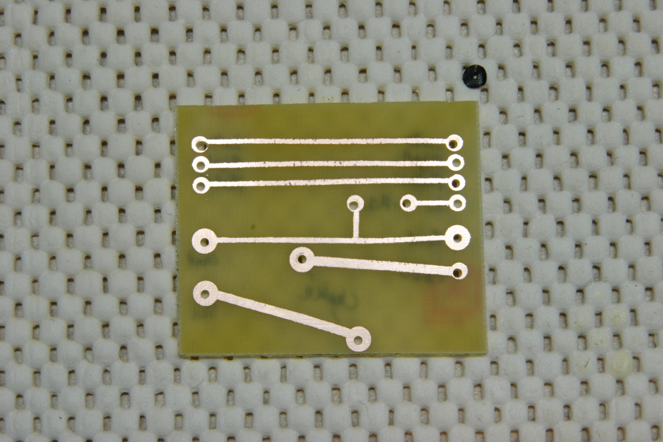
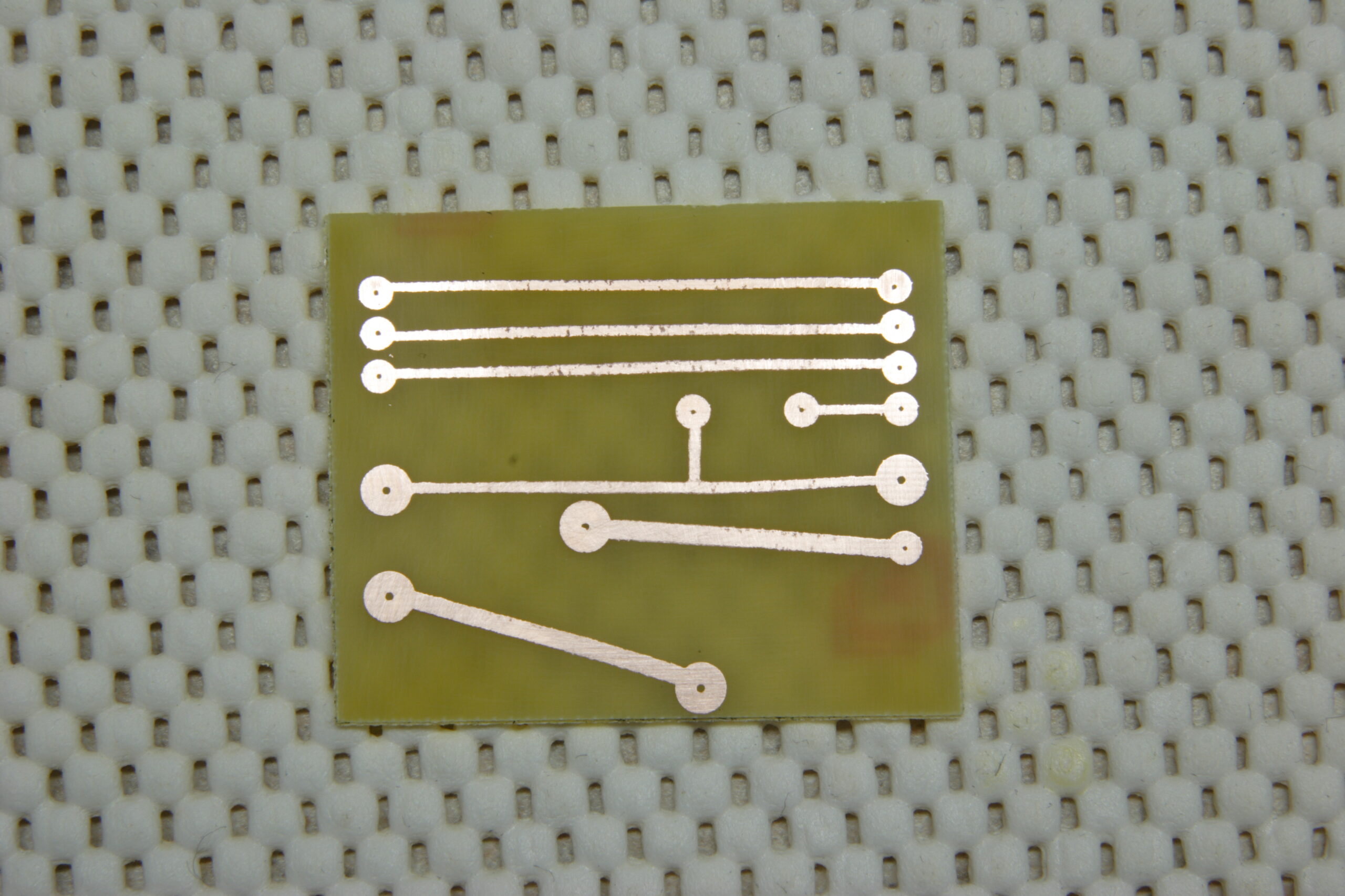
I think I’m also going to etch a PCB and mount it in a shielded (probably solid aluminum) box which will tie this all together. This will give me experience etching PCBs, and it’s a really simple project to start with. The box will be mounted somewhere beneath the iPod mount. There is a bracket inside the console which appears like it may be good for tying this to.

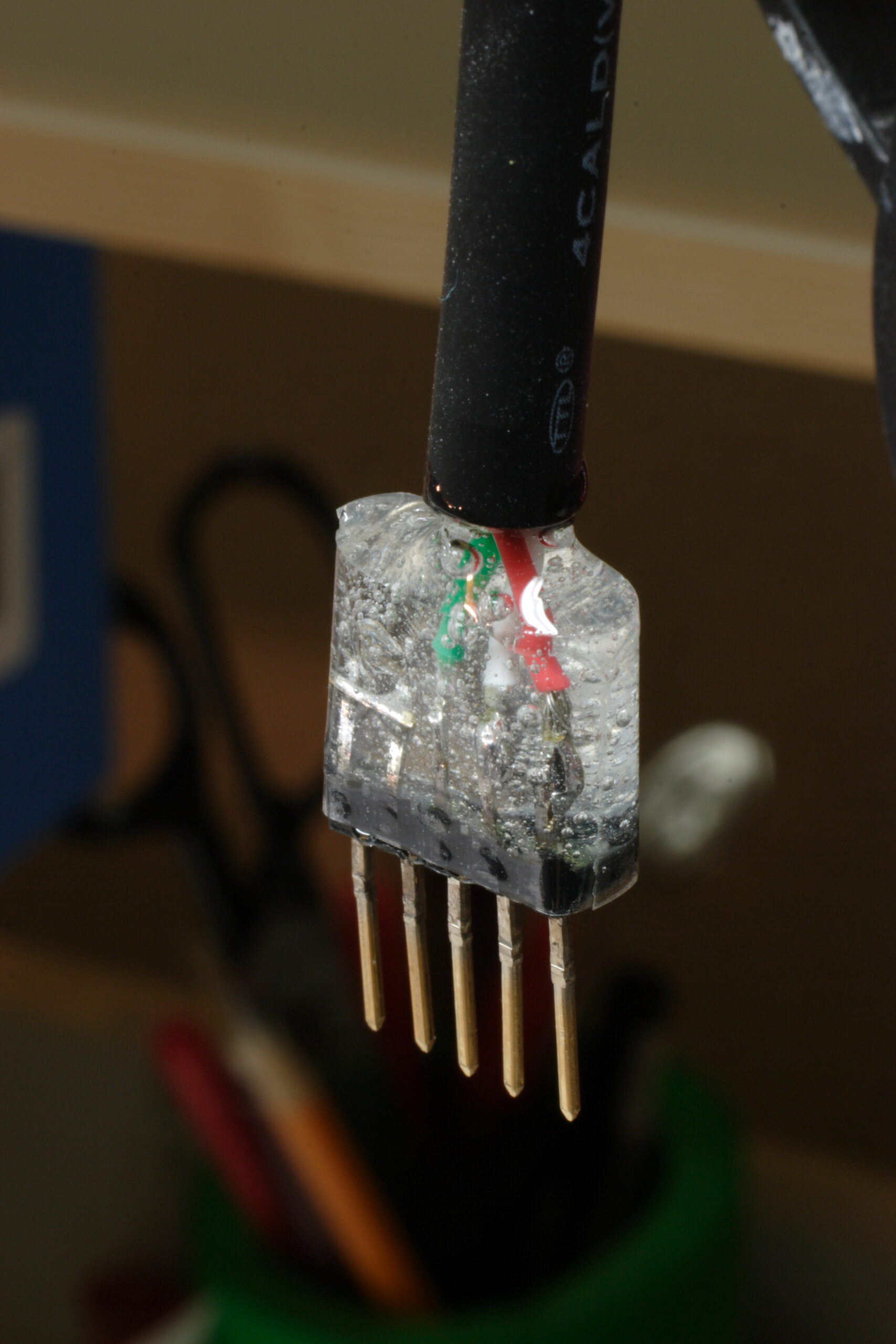
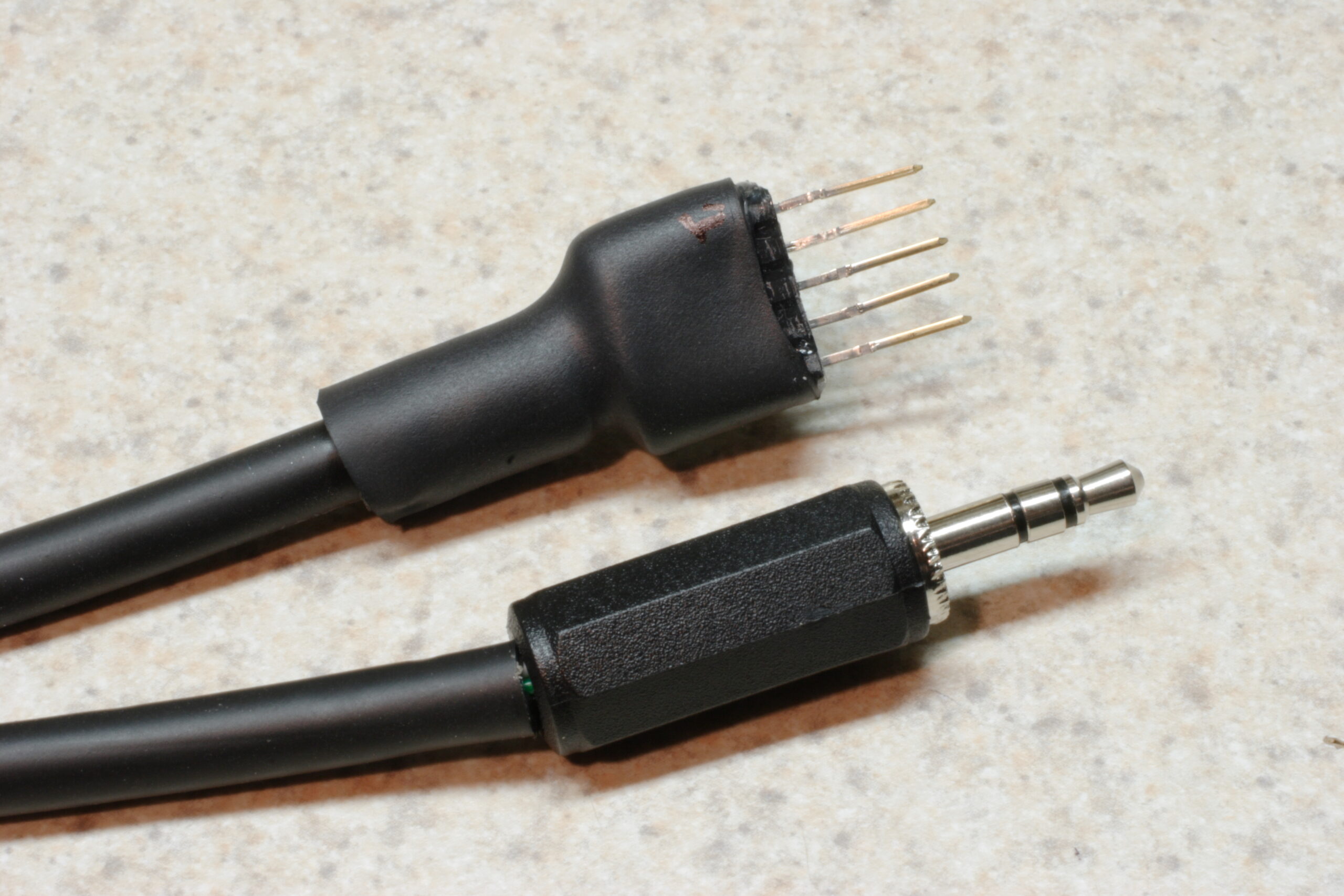
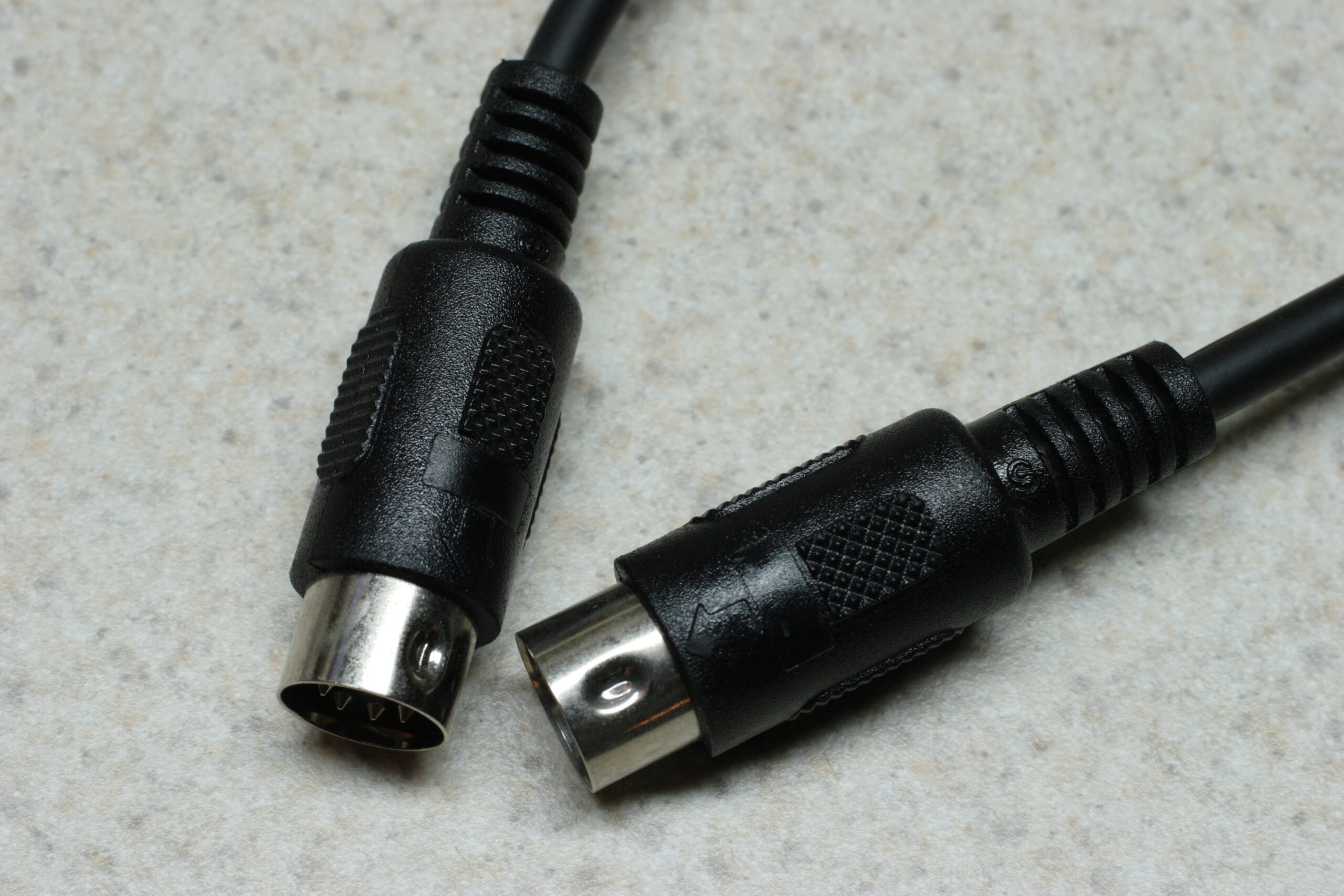
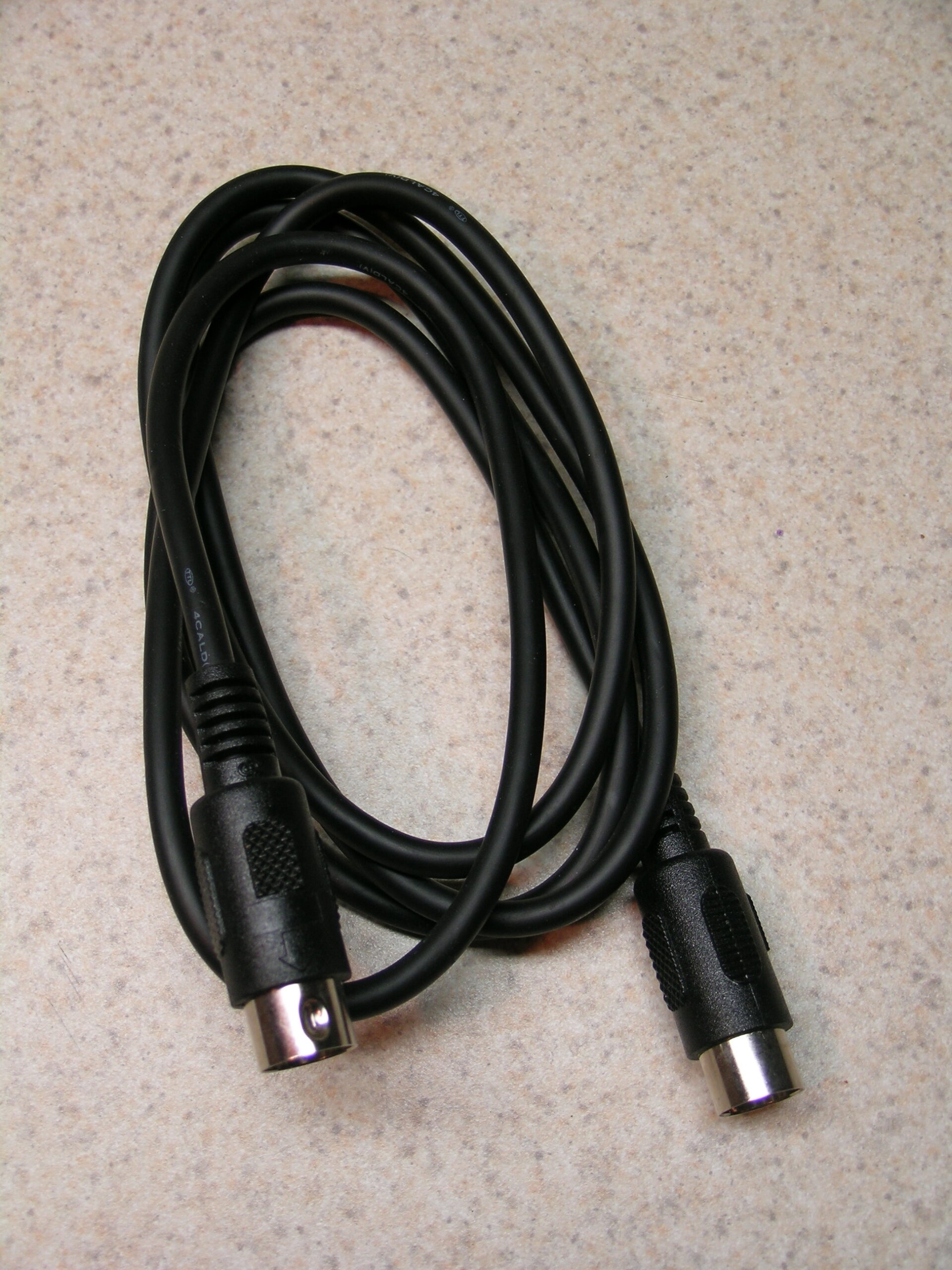
Just as when building the first version of my iPod adapter for this car, another MIDI cable will likely be sacrificed for making the connection to the Aux In. I’m not sure what I’ll do for power wiring yet. That’ll have to get figured out later. Maybe some random 18 gauge or 20 gauge or whatever I’ve got laying around the basement twisted together with some shrink tubing or tech flex over it or something. < shrug >

Oh, and completely unrelated to everything else I’ve mentioned in this post, I also updated yesterday’s LJ post which mentions Bell’s Sparkling Ale with a non-screwed-up photo. You can see that photo here if you would like.

automotivemaking thingsmoved from livejournal

Lowel ego

Wow, the Lowel ego looks like exactly the kind of lighting setup I need.

Then again, I could probably make something similar for a bit less… But it at least gives me some ideas. Maybe a nice diffuse lighting kit will be my next project after the in-car iPod mounting and the MAME machine.

electronicsmaking thingsmoved from livejournal

iPod + Civic Brainstorming

Some ideas…

– Find a way to safely / easily / reversibly remove the door on the aux audio connector (probably pin + spring friction fit) and use a right angle connector.

– Trace pinout on cable between Nav unit and Music Link adapter box.

– Identify pins used for power. Likely pins 9 and 10 of connector E ‘BLU (SAT ECU BUS (+))’ and ‘PNK (SAT ECU BUS (-))’. May also be pins 1 and 11, ‘BLU (+B GA-NET)’ and ‘BLK (GA-NET GND)’.

– Adapt one half of 08A31-0F1-000 (BUS HARN 2PORT) to provide power to iPod (hopefully is +12v, otherwise cancel idea) and use other half to Honda Music Link. Probably wire-wrap / solder two pins in connector and heat shrink for insulation. Harnesses are cheap and readily available.

– Mount Belkin TuneDok in left side of storage area in front of gear selector. Use threaded sleeve from center of cupholder cut out and braced with large (trimmed?) washer. Bolt through bottom of stoarge area.

– Buy Belkin Auto Kit (Black) from eBay to acquire dock connector cable.

– Small PCB in project box holding 1MΩ resistor (to emulate Belkin Auto Kit and pause on power off). Probably will also patch audio from dock cable to 3.5mm plug and power from wires leading from BUS HARN 2PORT to dock cable.

– Appears to be space in console in front of gear select to mount small project box. There is a medium sized structural tube to which it could be cable tied (with padding, similar to how Music Link box is mounted).

– RF chokes on all audio lines inside of project box, just to be sure.

End result should be all-black mounting hardware. No changes to any factory wiring. Audio fed through factory connector, power pulled from the same place as iPod charging power is currently acquired. Power to iPod should be nice, clean power, filtered by whatever filters the power in the head unit making for no noise.

Before doing all that, I need to take my vehicle in and get the resonating sound I’ve been hearing when the engine is running at 1400-1500 RPM checked out. I think this is a common problem. I also need to get my iPod taken care of at some point, because I think the disk in it may be dying.

Okay, end of rambling.

automotiveelectronicsmaking thingsmoved from livejournal

MAME Cabinet

Well, talking to some #llamasoft people got me thinking… I should just replace the monitor in my MAME cabinet with a real, decent sized one. So I think I’m going to see if the Vision Pro 27″ SVGA Universal Mount Monitor from Happ Controls. It’s US$349.95 for the tube, plus another $13.15 for the monitor bezel. As long as it’ll fit in my cabinet, I think I may go that route… It’d be a great, massive display which would actually accept a VGA signal.

Hrm… That really would polish off the cabinet…

electronicsmaking thingsmoved from livejournal

Painting…

Blah. I kinda screwed up in painting part of my MAME monitor. I didn’t paint enough of the bezel, so when one looks into the monitor at a very low angle, there is still some beige visible. I’ll have to fix this another day. :(

making thingsmoved from livejournal

Arcade Update

Well, the plans to run AdvanceMame under Linux on my arcade game are now out the window. It just seems too complex for what I’m wanting to do.

I’m now going to try it with FreeDOS for sake of simplicity.

If things go according to plan, I’ll have the whole thing (nearly silently) running off of a CF card by this time next month. (Waiting for parts…)

computersmaking thingsmoved from livejournal