nuxx.net
Making, baking, and (un-)breaking things in Southeast Michigan.

Category making things

iPod + Civic Brainstorming

Some ideas…

– Find a way to safely / easily / reversibly remove the door on the aux audio connector (probably pin + spring friction fit) and use a right angle connector.

– Trace pinout on cable between Nav unit and Music Link adapter box.

– Identify pins used for power. Likely pins 9 and 10 of connector E ‘BLU (SAT ECU BUS (+))’ and ‘PNK (SAT ECU BUS (-))’. May also be pins 1 and 11, ‘BLU (+B GA-NET)’ and ‘BLK (GA-NET GND)’.

– Adapt one half of 08A31-0F1-000 (BUS HARN 2PORT) to provide power to iPod (hopefully is +12v, otherwise cancel idea) and use other half to Honda Music Link. Probably wire-wrap / solder two pins in connector and heat shrink for insulation. Harnesses are cheap and readily available.

– Mount Belkin TuneDok in left side of storage area in front of gear selector. Use threaded sleeve from center of cupholder cut out and braced with large (trimmed?) washer. Bolt through bottom of stoarge area.

– Buy Belkin Auto Kit (Black) from eBay to acquire dock connector cable.

– Small PCB in project box holding 1MΩ resistor (to emulate Belkin Auto Kit and pause on power off). Probably will also patch audio from dock cable to 3.5mm plug and power from wires leading from BUS HARN 2PORT to dock cable.

– Appears to be space in console in front of gear select to mount small project box. There is a medium sized structural tube to which it could be cable tied (with padding, similar to how Music Link box is mounted).

– RF chokes on all audio lines inside of project box, just to be sure.

End result should be all-black mounting hardware. No changes to any factory wiring. Audio fed through factory connector, power pulled from the same place as iPod charging power is currently acquired. Power to iPod should be nice, clean power, filtered by whatever filters the power in the head unit making for no noise.

Before doing all that, I need to take my vehicle in and get the resonating sound I’ve been hearing when the engine is running at 1400-1500 RPM checked out. I think this is a common problem. I also need to get my iPod taken care of at some point, because I think the disk in it may be dying.

Okay, end of rambling.

automotiveelectronicsmaking thingsmoved from livejournal

MAME Cabinet

Well, talking to some #llamasoft people got me thinking… I should just replace the monitor in my MAME cabinet with a real, decent sized one. So I think I’m going to see if the Vision Pro 27″ SVGA Universal Mount Monitor from Happ Controls. It’s US$349.95 for the tube, plus another $13.15 for the monitor bezel. As long as it’ll fit in my cabinet, I think I may go that route… It’d be a great, massive display which would actually accept a VGA signal.

Hrm… That really would polish off the cabinet…

electronicsmaking thingsmoved from livejournal

Painting…

Blah. I kinda screwed up in painting part of my MAME monitor. I didn’t paint enough of the bezel, so when one looks into the monitor at a very low angle, there is still some beige visible. I’ll have to fix this another day. :(

making thingsmoved from livejournal

Arcade Update

Well, the plans to run AdvanceMame under Linux on my arcade game are now out the window. It just seems too complex for what I’m wanting to do.

I’m now going to try it with FreeDOS for sake of simplicity.

If things go according to plan, I’ll have the whole thing (nearly silently) running off of a CF card by this time next month. (Waiting for parts…)

computersmaking thingsmoved from livejournal

Stuff done today…

Well, since Kompressor has taken his site down, I have mirrored it here.

I also just finished upgrading the hardware in my MAME cabinet. The Slackware 10.2 discs are coming down via BitTorrent right now, then I’ll get to work on redoing the software. I’ll also try and get some good photos of it once it is done, too.

computersmaking thingsmoved from livejournal

MAME :(

Crap. The sound card in my MAME cabinet just died.

I’ve got plan to replace the innards of the machine, but I was hoping things would hold out through tonight.

Ah well, no MAME cab for a few days…

electronicsmaking thingsmoved from livejournal

Let’s do the time warp again…

Okay, so from last night around the time I got home until today just after I got home, I captured 2762 individual frames in an attempt to make a stop motion video of last night’s snow storm. One frame was captured every ~30 seconds, then those were all squished into a video running at 30 frames per second, making each second of cover 15 minutes.

The video is available here if you would like to see it:

08 – 09 December 2005 Snow Storm Timelapse (~12MB, H.264, 640 x 480 @ 30fps)

I apologize about the screen in the window, but it is non-trivial to remove it. Also, it appears the window is much dirtier than I thought, but I was having a hard time telling that last night, so I just ended up shooting through the dirty window. Ah well, at least it’s kinda nifty.

I’m sure there will be plenty of other snow storms this year. Next time I really want to have a camera that can be controlled by Apple’s Image Capture and have each photo taken automatically downloaded to the local machine. Now that could make for some nifty time lapse video.

making thingsmoved from livejournalweather

Phase 1: Done


Click for more…

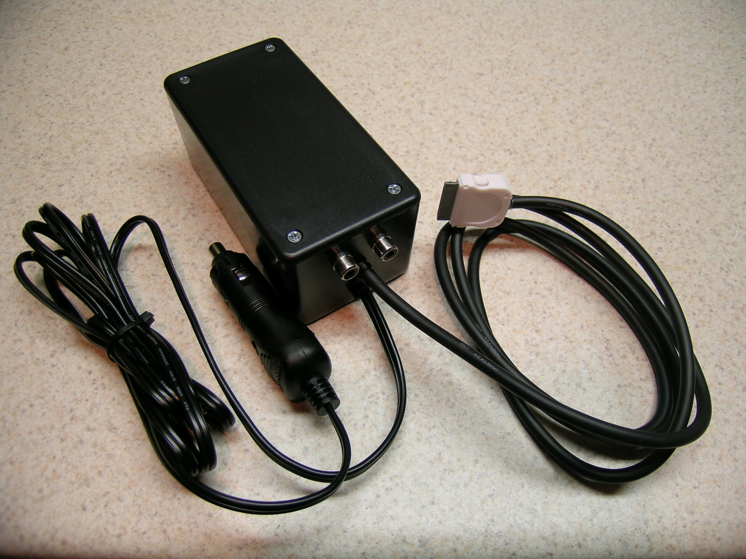
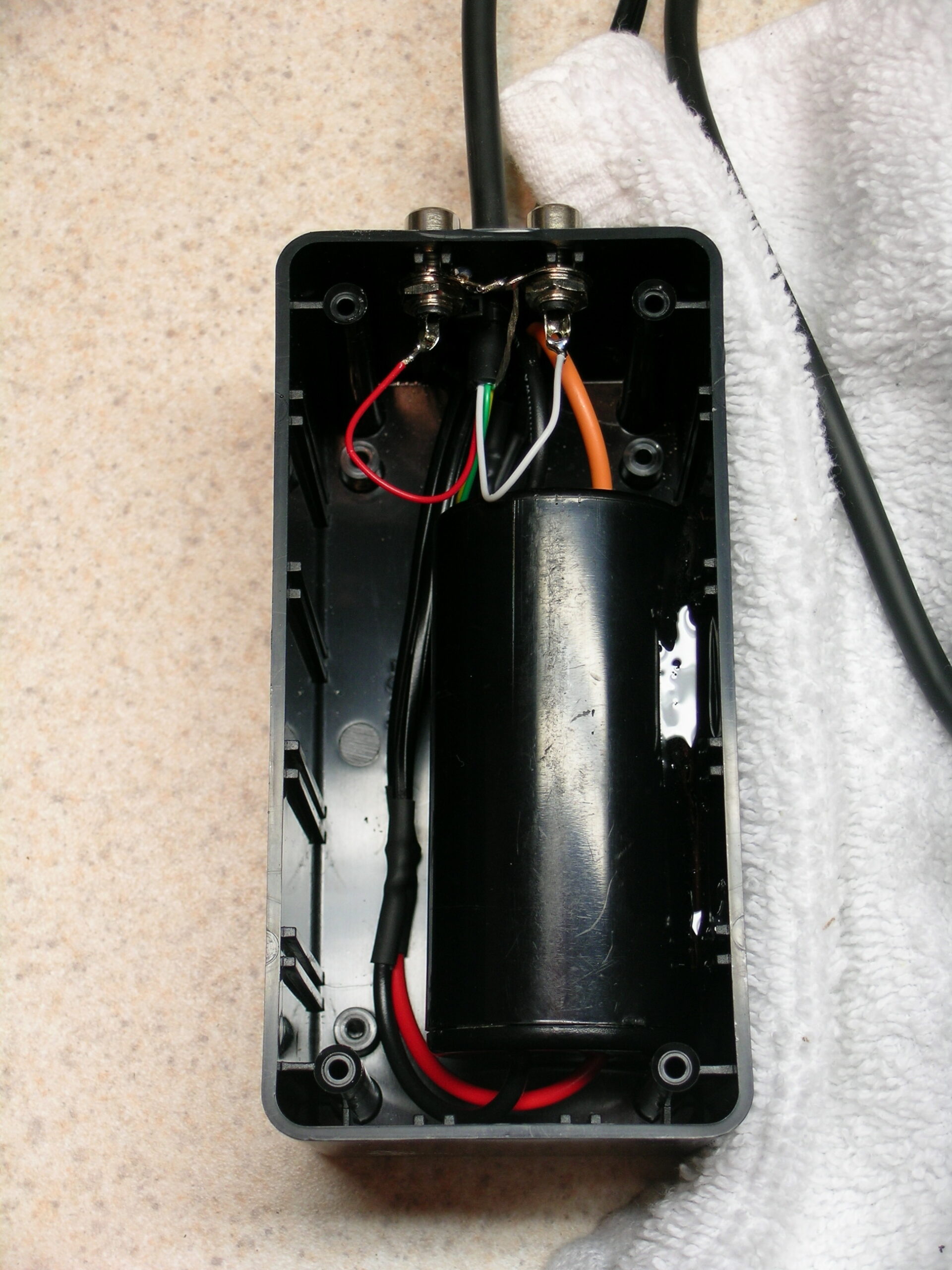
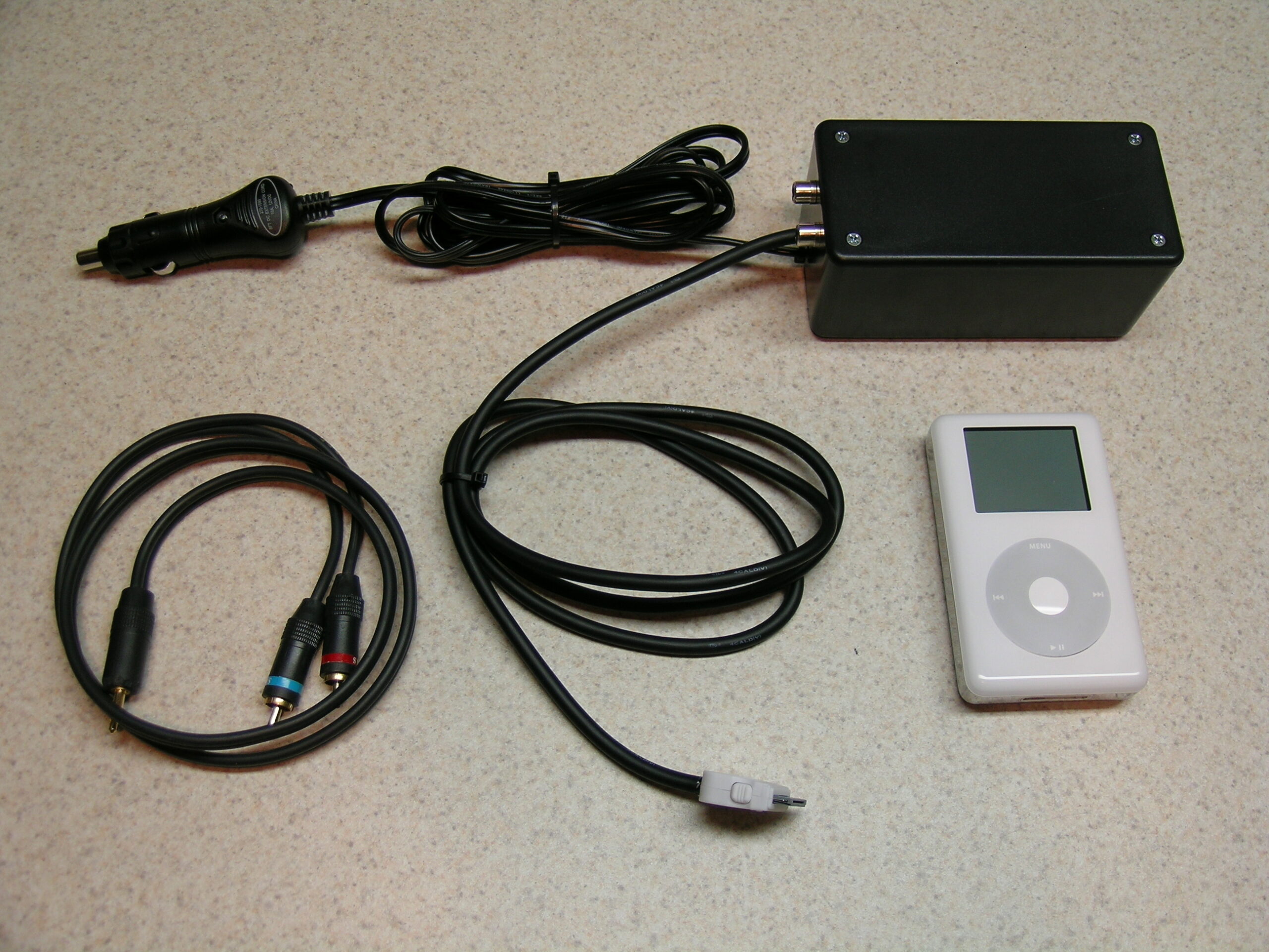
Ahh, phase one of the project to ‘properly’ connect an iPod to a 2006 Honda Civic is done. In short, I built this box and the cable running to the iPod. The box contains a filter to (hopefully) cut down on car engine noise and the break-out to provide the audio signal as two RCA connectors.

Inside of the shell of the iPod connector itself is a 1MΩ resistor which signals to the iPod that it has a car adapter connected so it should pause the iPod when power is disconnected, as this would typically happen when the car is shut off.

For now I’ll use this bundle of hardware to connect the iPod to the new car. It’ll power/charge the iPod, pause it when things are disconnected, and provide audio into the ‘aux in’ connector.

The next phase of the project is to wire the box (or perhaps just the iPod cable) into the car itself, either via factory-compatible connectors or straight hard wiring. My goal is to have the iPod powered from a keyed, filtered accessory line and the line-out to run straight into wherever the aux in connects to. I also want the iPod nicely mounted in a good location, within arm’s reach, and easy to navigate while driving. That kind of fitting (along with the factory-type connectors) I can’t do until I have the vehicle.

But, yeah. At least this much is done.

automotiveelectronicsmaking thingsmoved from livejournal

It Works


Click for more…

Well, the damn thing works. I got the connector wired properly, closed it up, and tested it with a 12v supply from the car. The iPod charges, and if it is playing and the power is disconnected, the iPod pauses. Tomorrow I’ll go get the stuffs to enclose the power filter and end-of-iPod-cable junction in a box. I’ll also stick a pair of RCA jacks on the outside of the box so that I can get audio out of it all.

I should have left the DIN5 on the far end of the cable for the time being so that it could have simply been plugged into the project box, but that’s okay.

The end result of this should be a temporary single cable iPod hookup which I can use until I get the car’s wiring figured out, connectors ordered, etc.

Earlier while working on this I became pretty frustrated with myself because after screwing up the first connector I made a second. Everything was going absolutely great until I realized that I’d wired it backwards, mixing up pins 1 and 30. And it was going so well, too. Ah well, at least it’s set for the time being. I’ve already got the RCA panel connectors, so I just need a project box. That shouldn’t be too hard to come across, I hope.

Now, I just wish I was tired. I thought the coffee I grabbed on the way home from ‘s place was a bad idea. It was. I’m nicely awake.

UPDATE: I forgot to mention what a pain it is to solder inside of these connectors. They are 0.6mm pins spaced 0.6mm apart. To make it a bit easier I took to removing unneeded pins from the last connector used, the one that was properly done.

See? Top · Bottom

An easier way to think of it is in regards to mechanical pencil lead. Most mechanical pencils that people use are either 0.5mm or 0.7mm. Most rollerball pens that people use make a 0.7mm wide line. That should give you an idea of what I was working with. Soldering one (or sometimes two wires) to something that small is a bit interesting.

automotiveelectronicsmaking thingsmoved from livejournal