PAiA FatMan Rebuilding Goes Awry…
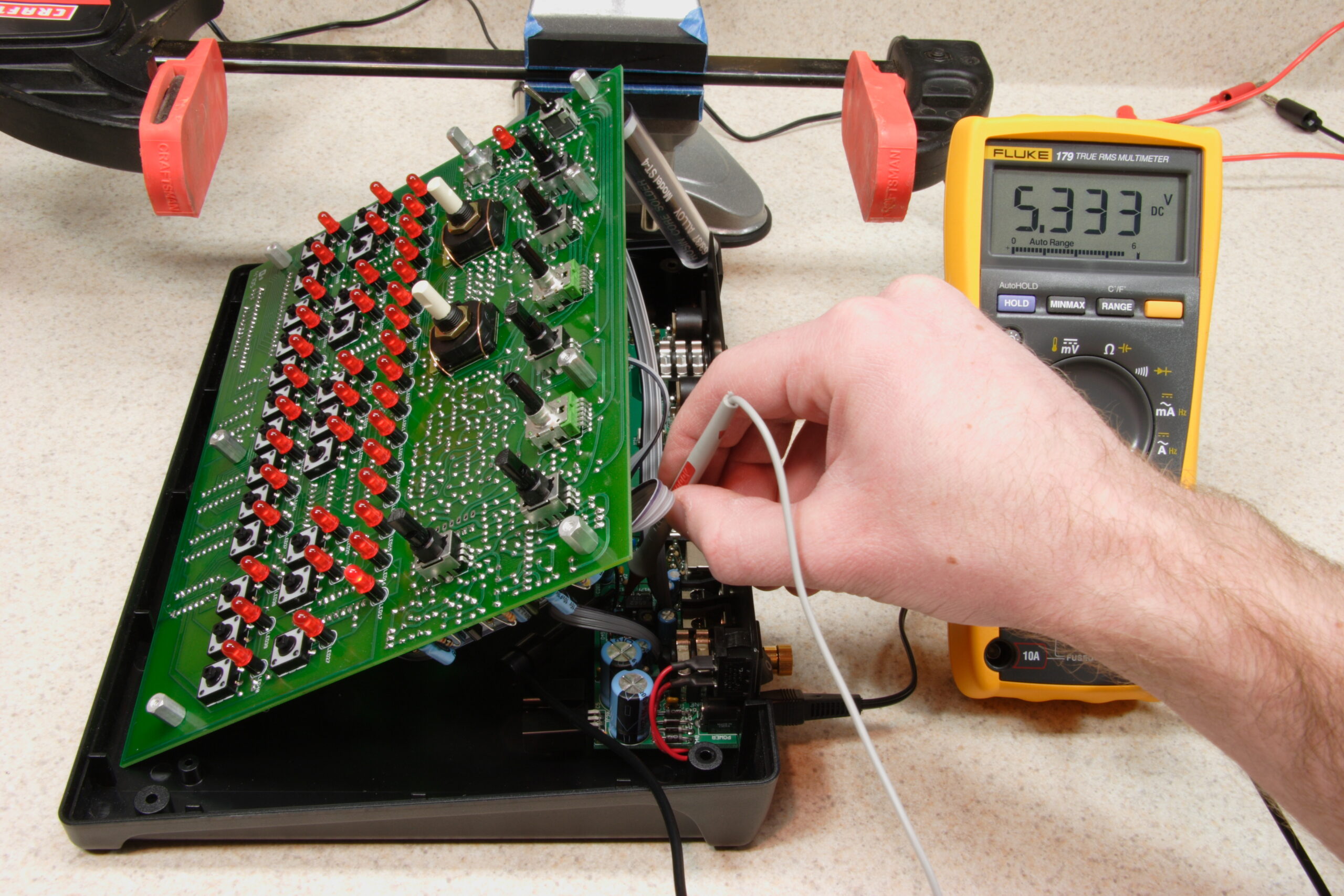
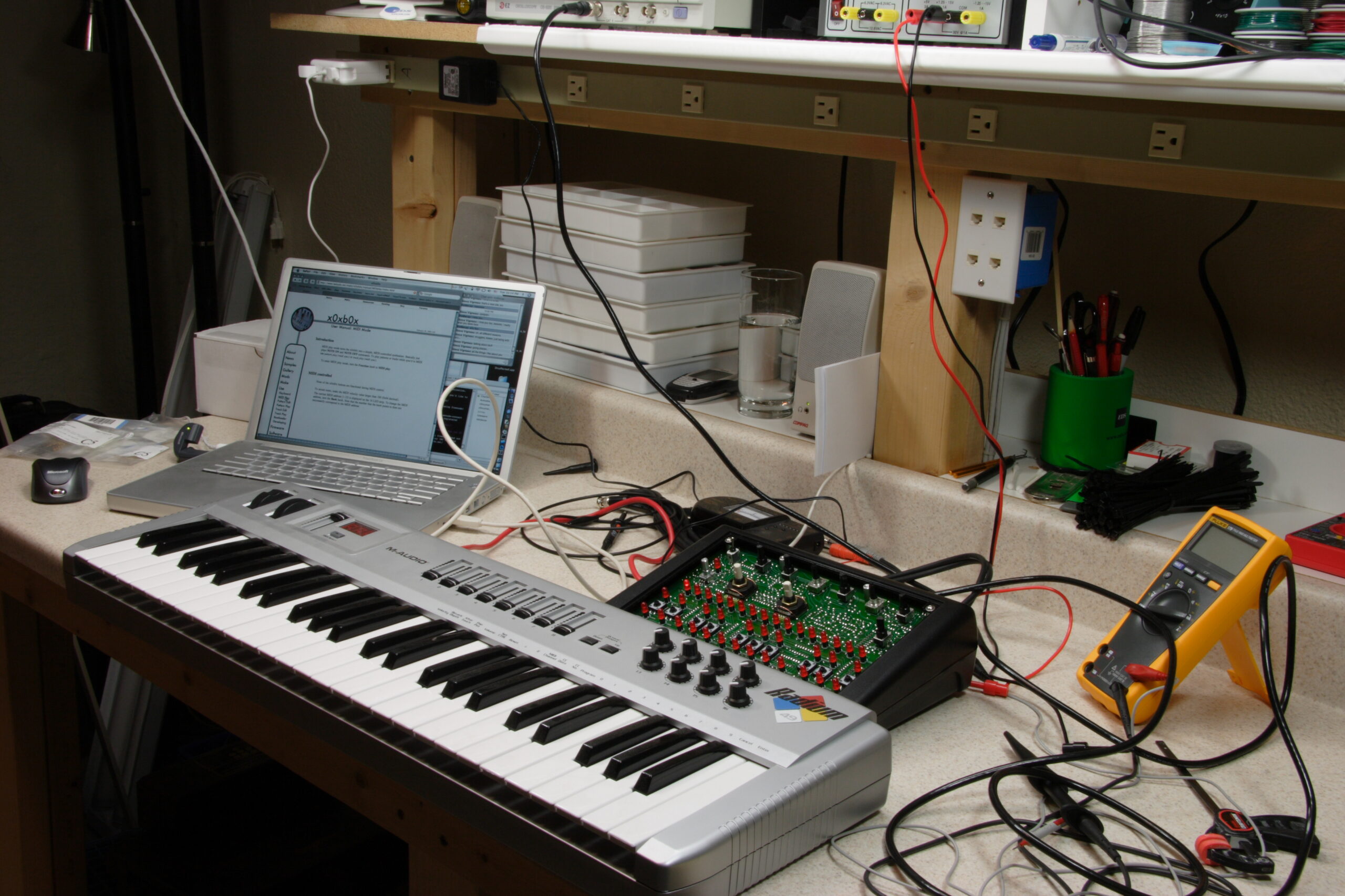
Tonight I got the modifications to my PAiA FatMan all implemented. Unfortunately, after powering it back up I realized that it wasn’t quite working any more.
When I press a key, I’m getting a single shot of sound for each key press, in a way which almost sounds to be as if the synth is generating a single wave and then stopping. Both VCOs are doing this.
The VCF still seems fine as does the VCA, and I’ve triple-checked everything. I even went so far as to individually remove all the lines which actually implement the various modifications in order to rule them out.
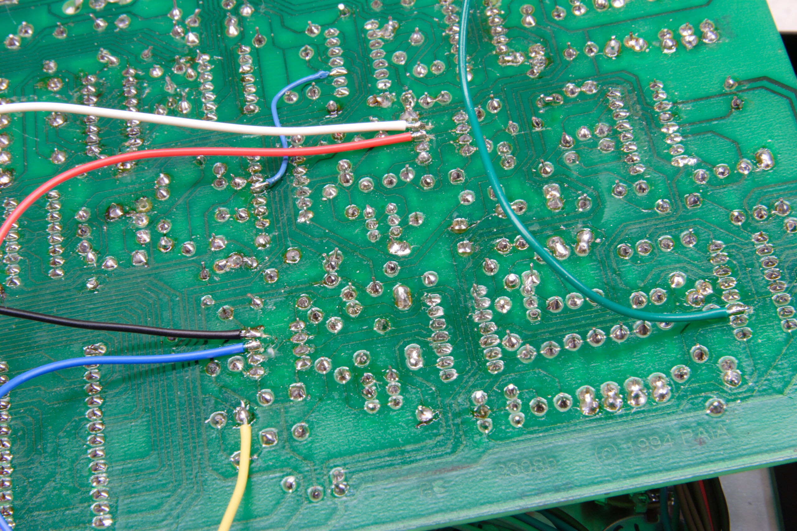
My current thought is that when attaching the wires to the back of the PCB I fried both of the new CMOS 555’s which I put in. My thinking is that non-functional timer, things can’t repeat, etc… It’s also the only thing I’ve touched since I had it working last night.
I’m fairly confidant that all the digital stuff on the board is still good, all the way through the midi -> cv part of it. The MIDI light blinks, the gate LED goes solid whenever a key is held down. Also, the VCF and VCA change the sound appropriately when one fiddles with the knobs. If I crank the release on the VCF way up, a sustained sound is heard. Even the modifications I made seem to be working, just for a very brief period of time.
Fortunately I had ordered four 555’s (originally only used two) and I’ve got some DIP8 sockets laying around, so tomorrow I’ll just replace them with socketed parts. I’ll also do one, test, then go from there…
I really, really hope that is the problem. I’d love to hear ideas if any of you think it could be something else. The schematic can be found near the end of this PDF.
However, the only points I did anything with on the board since it was working last night are the 555s, part of the VCF to provide audio in (soldered to a pin of an IC), and half of a resistor, so the 555s will be the first to be swapped tomorrow.
Oh, and it sounds really, really cool with these modifications. Much improved over the original.
UPDATE: Gur. I’m an idiot. Of course you’ll just get a burst of sound with ‘sustain’ in the VCF turned all the way down. Guh. Yeah, it’s working fine… I just need a new EPROM with new software on it to work around the FATMOP v1.8 (or whatever) MIDI bug.
