nuxx.net
Making, baking, and (un-)breaking things in Southeast Michigan.

Category making things

Casio SK-1 MIDI Adapter


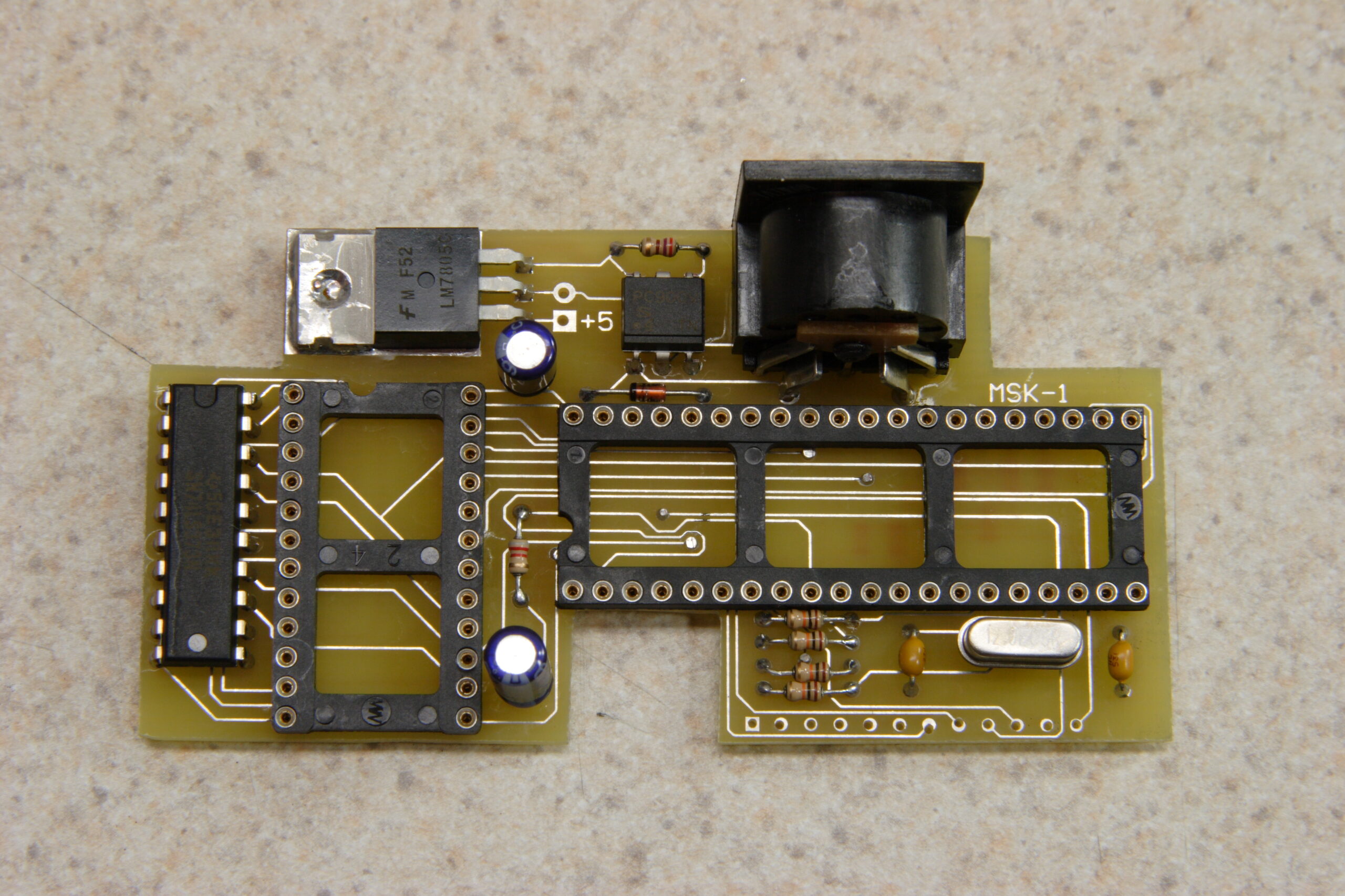
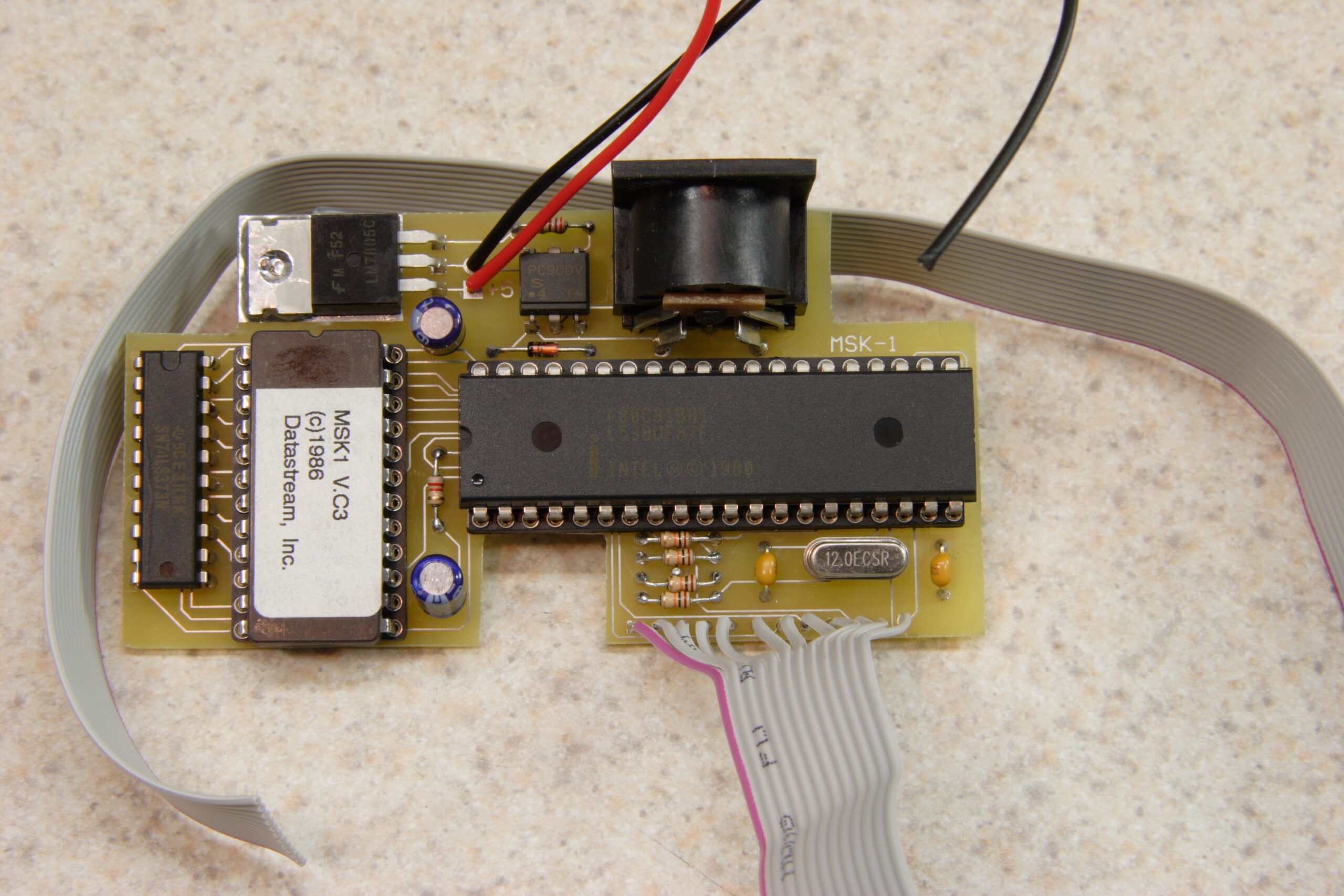
Completed Casio SK-1 MIDI Adapter
(Click for full res.)

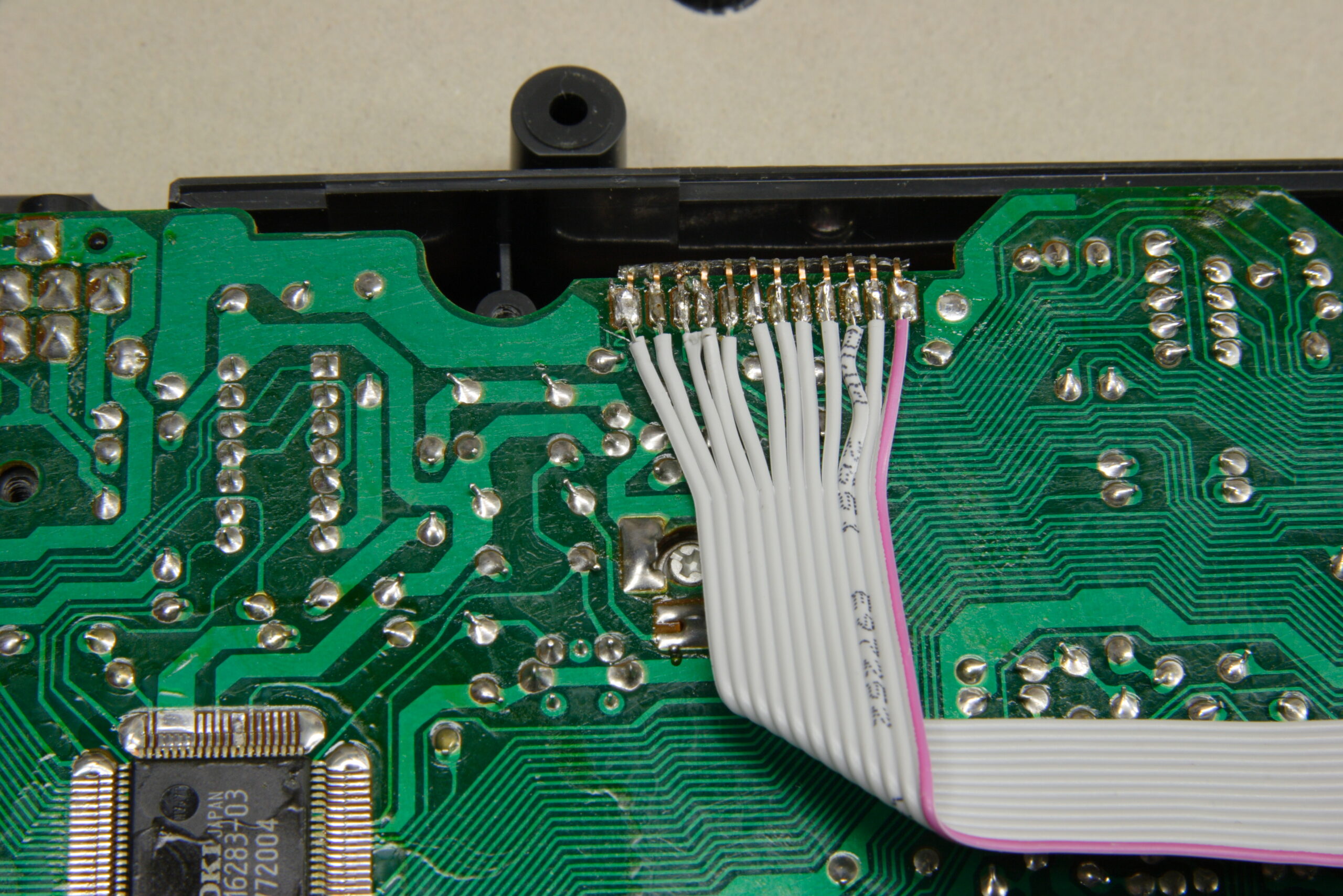
On the up side, I completed the PCB for the Casio SK-1 MIDI adapter that I’ve been working on. On the down side, it doesn’t work. After reassembling the SK-1 after cleaning it, everything seemed to work great. Then, after I hooked up power, fitted the PCB into the enclosure (without gluing it yet), and attached the ribbon cable to the SK-1’s keyboard connections, the SK-1 just makes a humming / buzzing sound. I think the problem is likely some part I missed soldering on top of the board or something. Or possibly a bad PCB-side connection on the ribbon cable.

When making one’s own double-sided PCB, the holes aren’t plated on the inside with metal, so one has to solder parts on both the top and the bottom of the PCB. It was a bit of a hassle to solder things on both sides, but I thought I it taken care of in most places. Maybe I’m wrong, though… Ah well, tonight (or sometime this weekend) I’ll remove the PCB, remove the power lines and ribbon cables, and double-check everything against the schematic.

Here’s some of the pictures from my work on this last night:

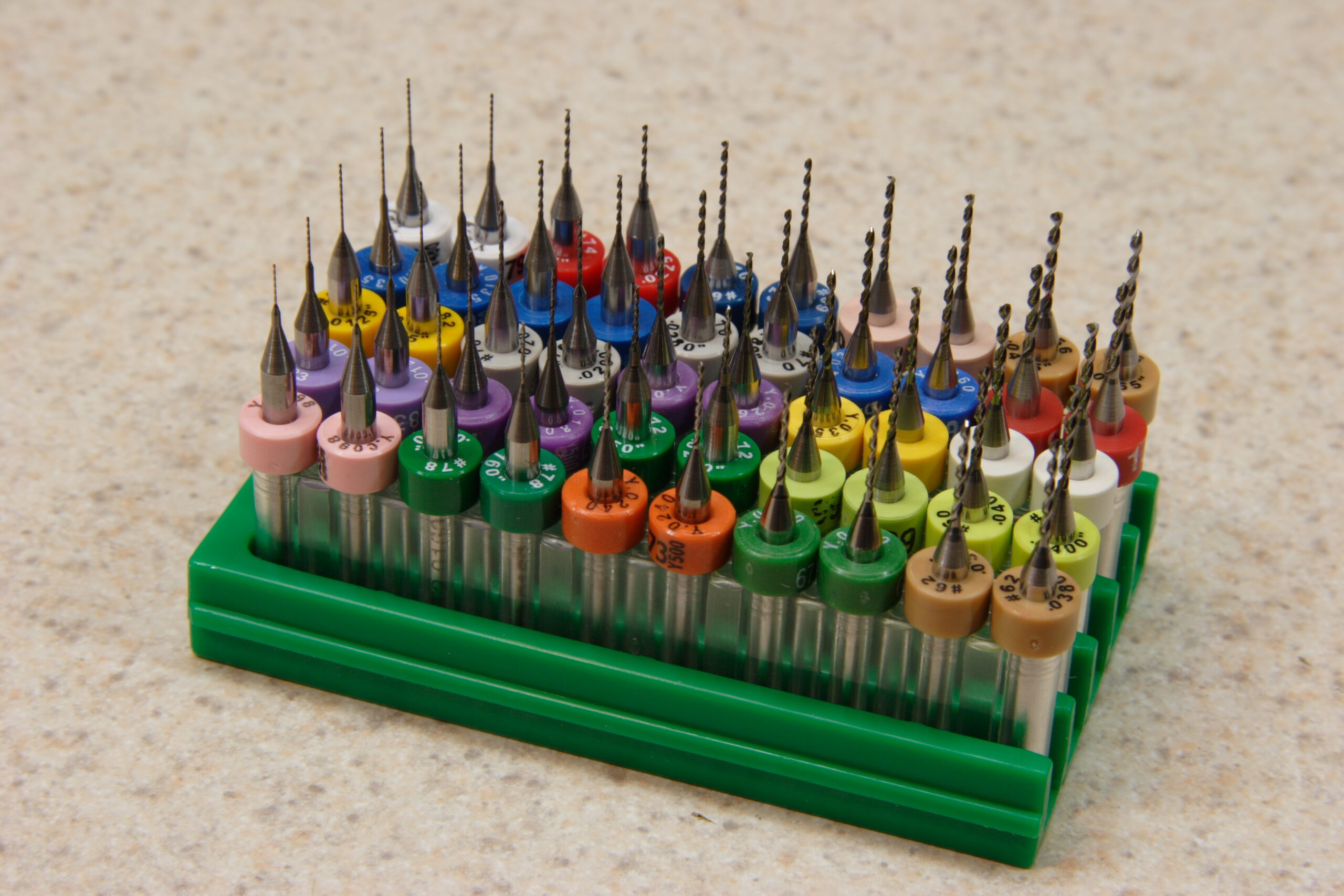
· Resharpened PCB drill bits, acquired from eBay. They are really, really small. The shafts on those bits is 1/8″.
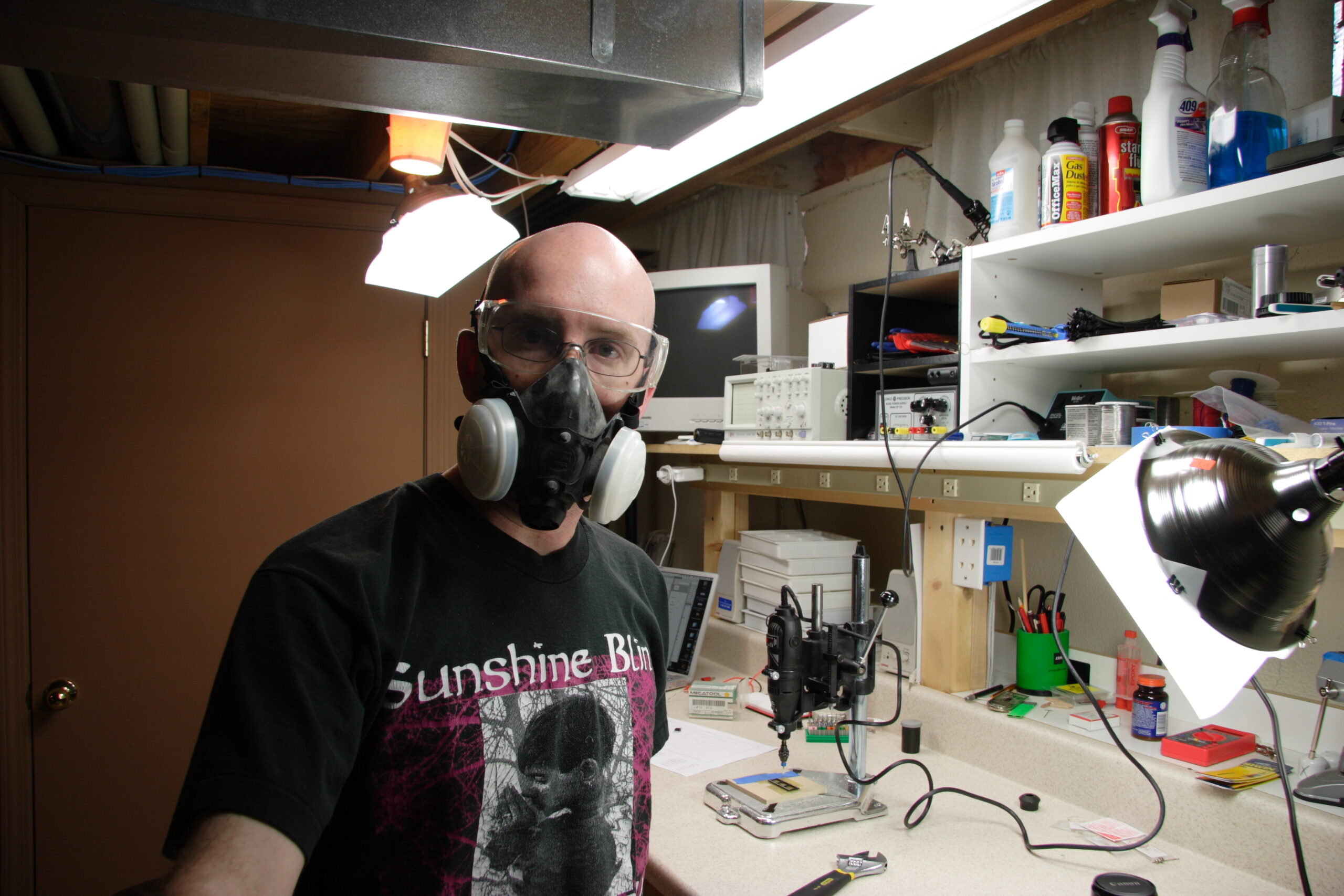
· A very unshaved me, wearing a respirator and safety glasses. Both are needed as drilling and cutting PCBs makes lots of fiberglass / epoxy dust.
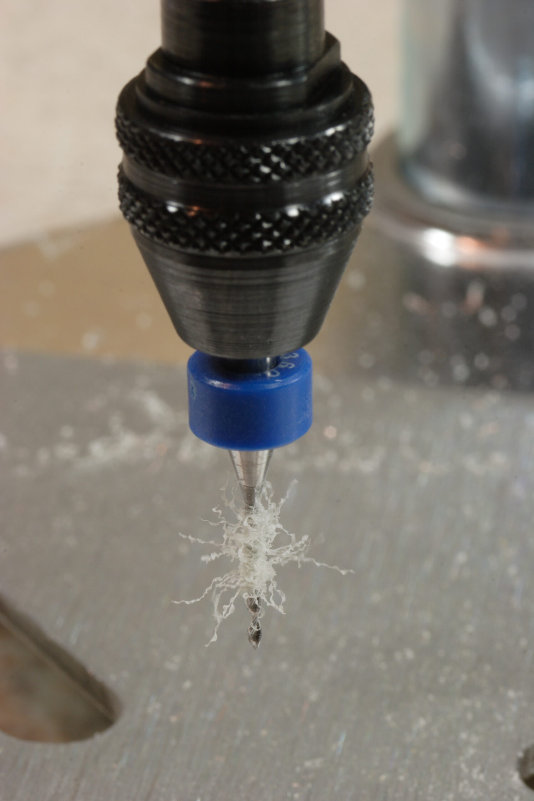
· One of the bits (26 mil, I think) in the chuck of my Dremel.
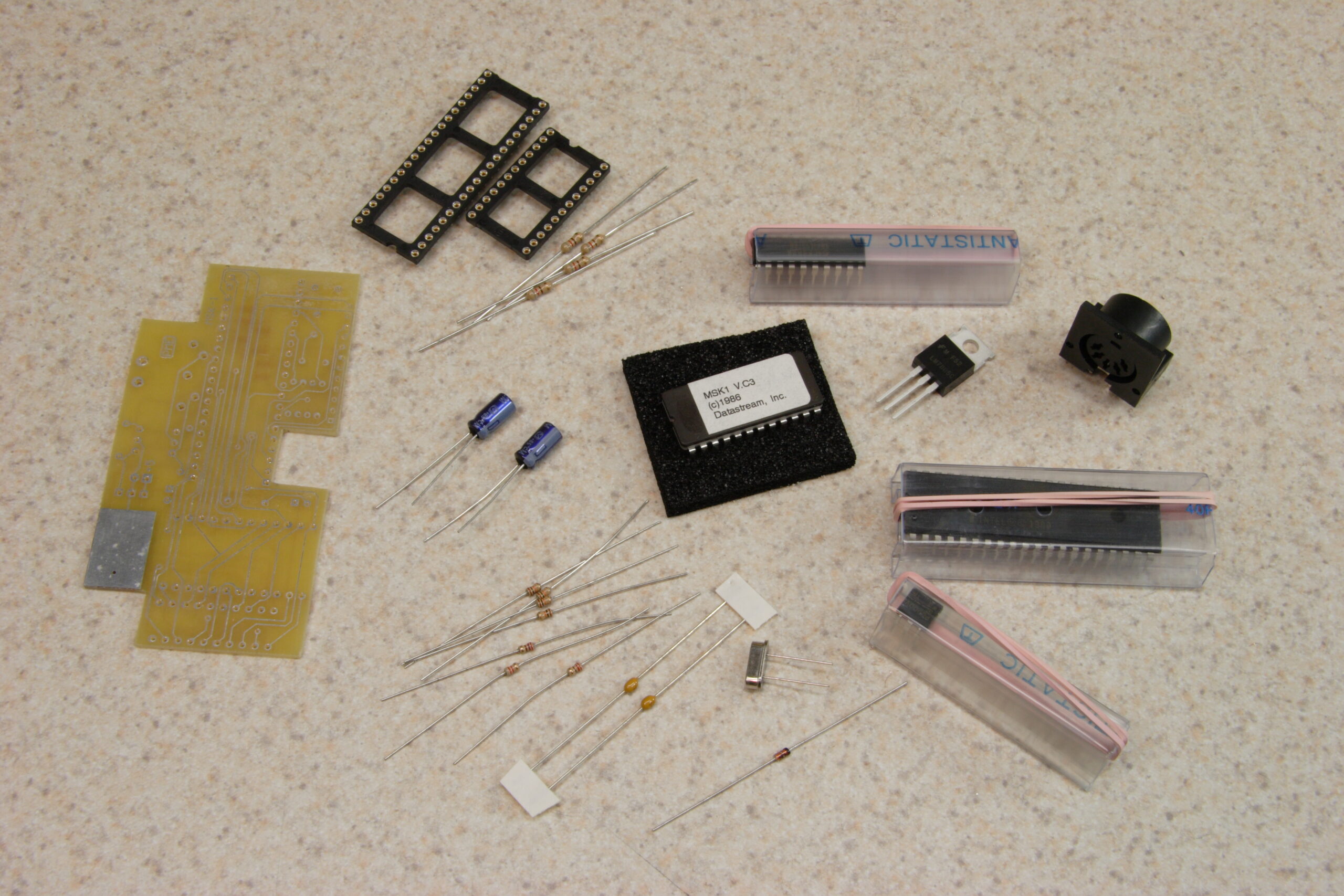
· The pile of parts needed for assembling the adapter, including some spare resistors sacrificed for their leads, which were needed to solder vias.
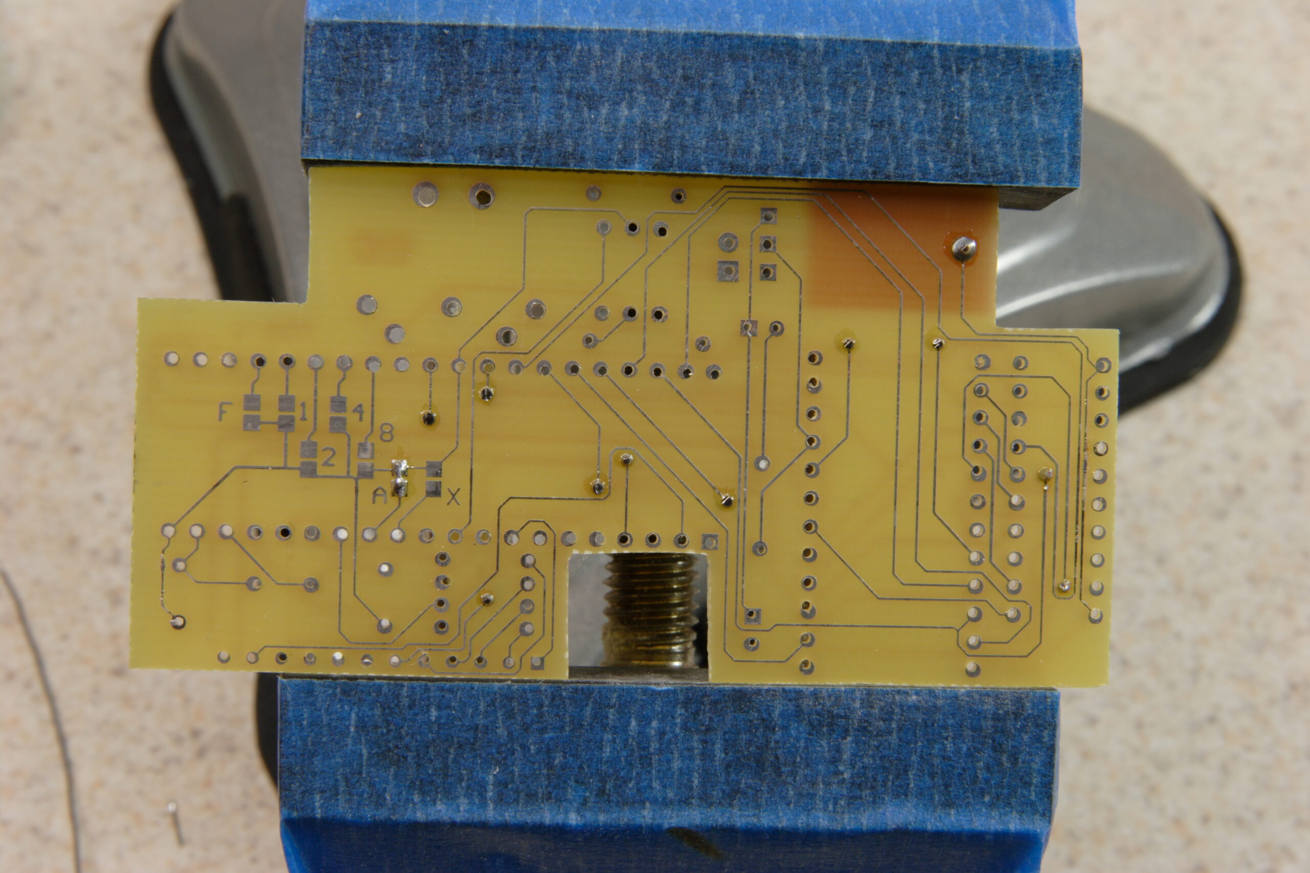
· All vias soldered, and jumper A placed to turn off wrapping of notes from outside the keyboard’s normal range.
· All parts (except for microcontroller, ROM, and wiring) attached to the board.
· Completed board, with power wires and ribbon cable.
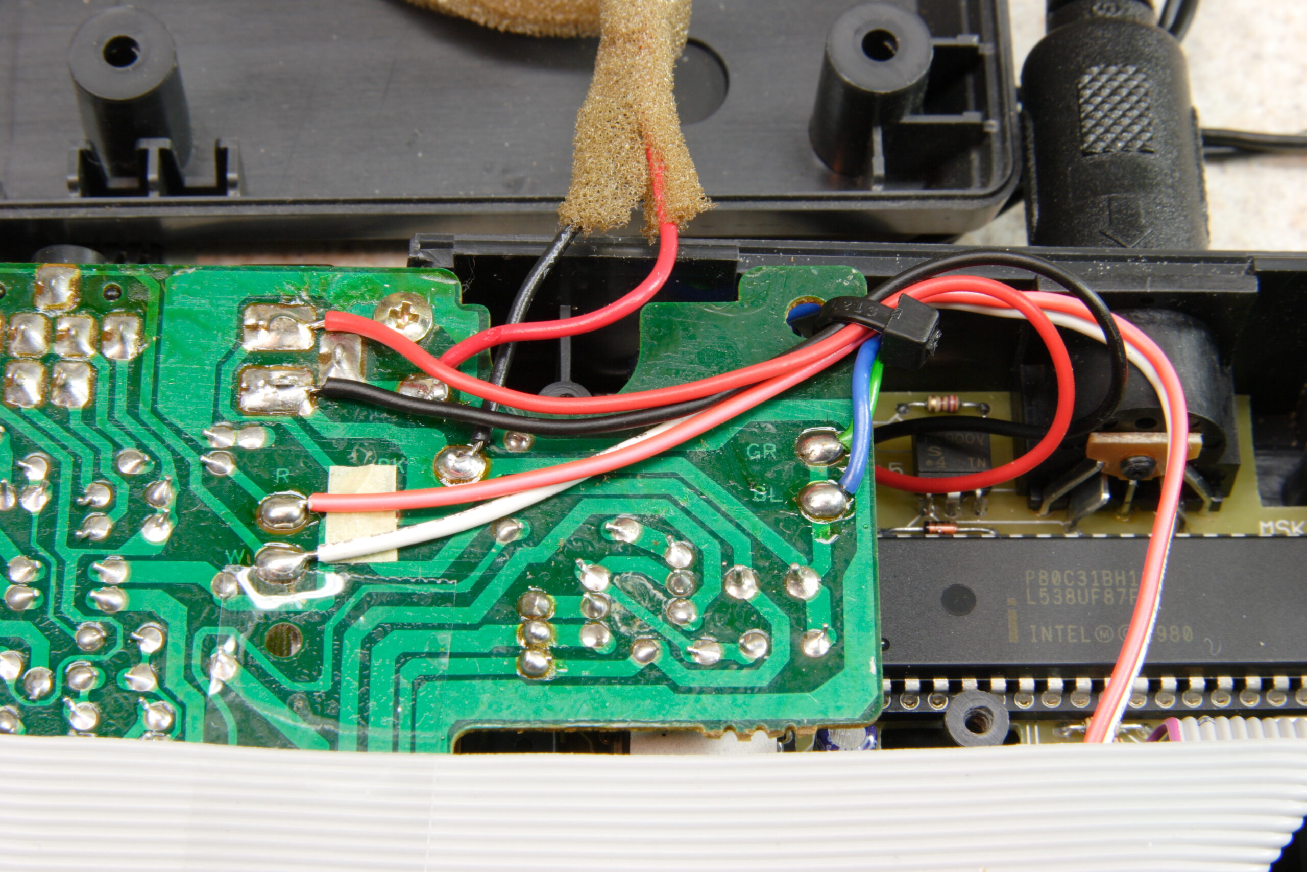
· Ribbon cable attached to Casio SK-1’s keyboard connection.
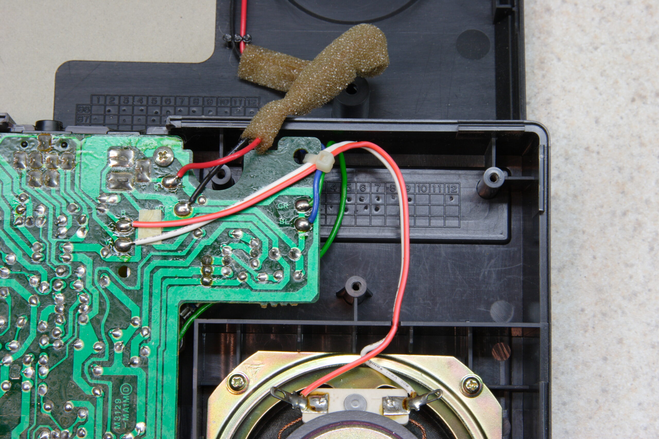
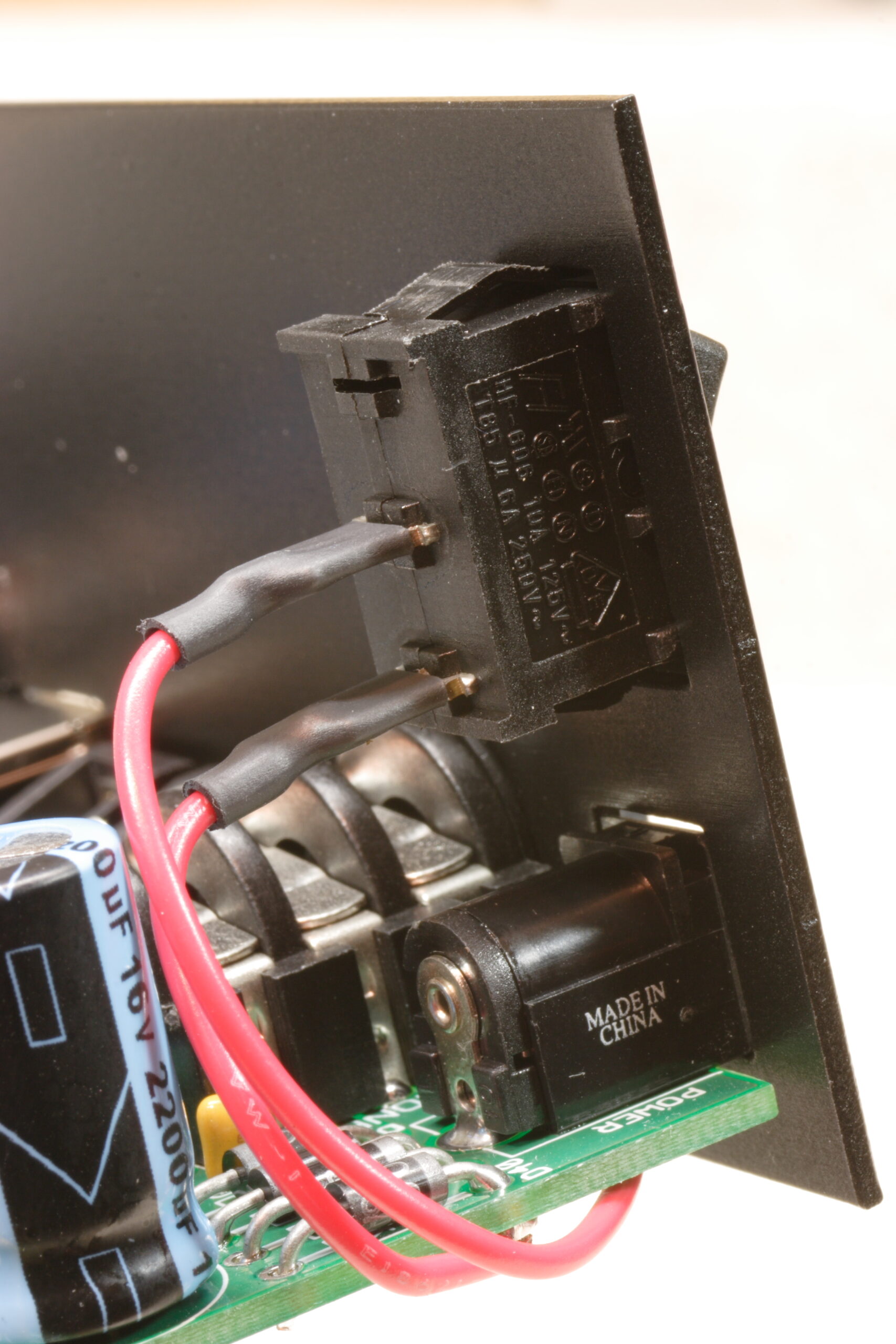
· Power wires attached to the external power jack and the PCB fitted next to the speaker.

So, that’s that. I’ve still got more to go with regards to fixing everything. I know it’s getting power… I just don’t know what else it is doing yet. By the time I had the board installed it was nearly 11pm and I’d been working on everything for about 4.5 hours. I needed a break. Hopefully things will progress further tonight / this weekend. At least I don’t work until Monday or so.

electronicsmaking thingsmoved from livejournal

Power Supply Woes

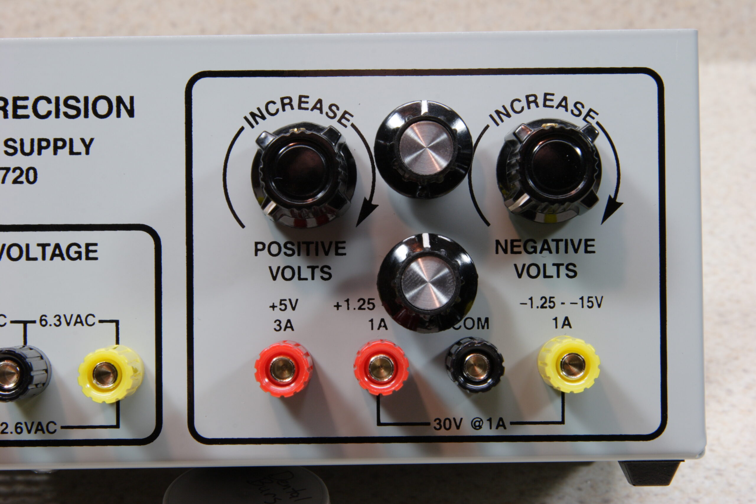
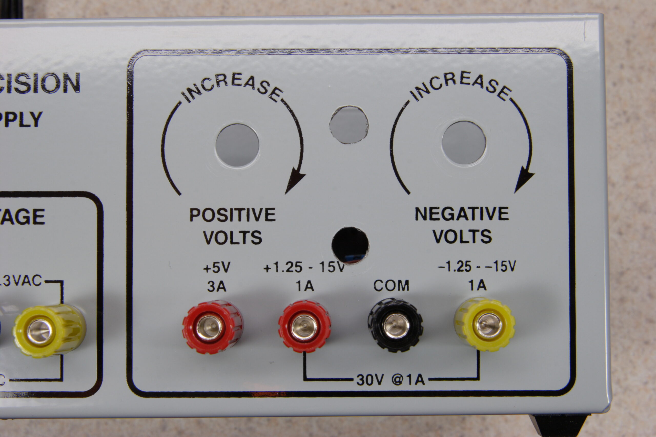
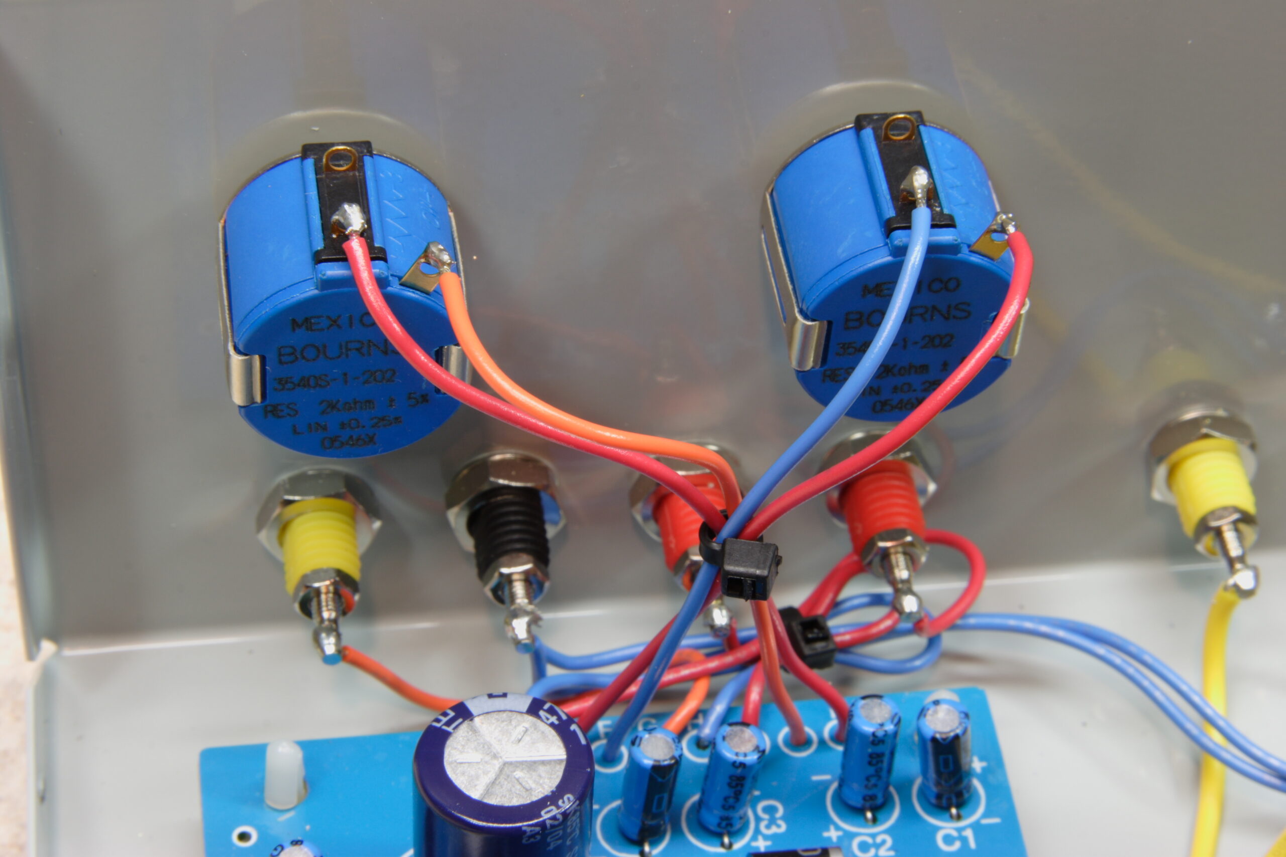
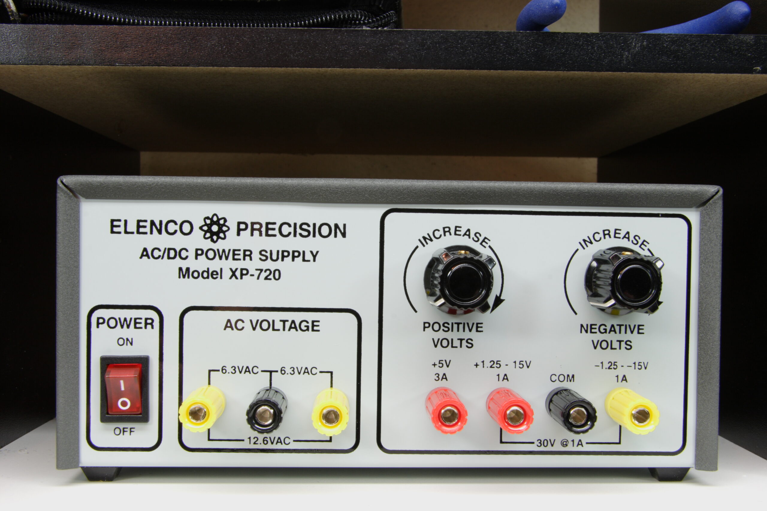
Hmm, so yesterday I added two more pots (2Ω, wired in series with the other ones) as a fine tune adjustment on my Elenco XP-720K (photo gallery retired). Despite being a bit unattractive it was working great, until I went to use it today. I turned it on, off, then back on, and the fuse blew. It’s just a small 1A fuse, so maybe the shock of bouncing it around for a bit caused it to go, but it still worries me a bit.

I don’t know what could have caused this, except for something being shorted out. But I had simple banana plug leads between it and my meter (to set it to exact 5.000VDC) and nothing else. I guess I’ll go get some more 1A fuses, stick a new one in, and wait and see if the problem comes up again. I’m hoping it was just a cheap fuse and thermal / mechanical stress on the fuse itself. Hmm, I guess it did get shaken around quite a bit while I was drilling out the extra holes in the front panel. The steel is really hard, so it took a bit of work.

electronicsmaking thingsmoved from livejournal

Casio SK-1 MIDI Modification


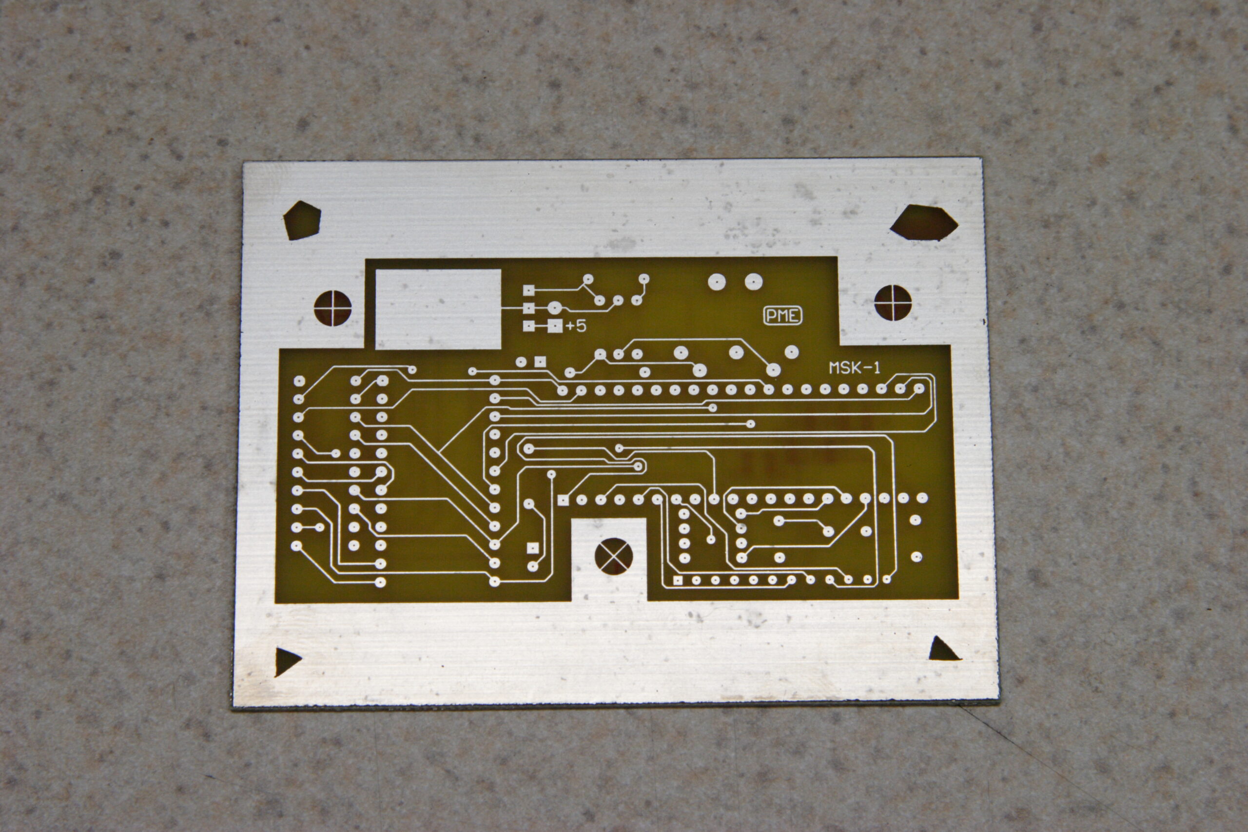
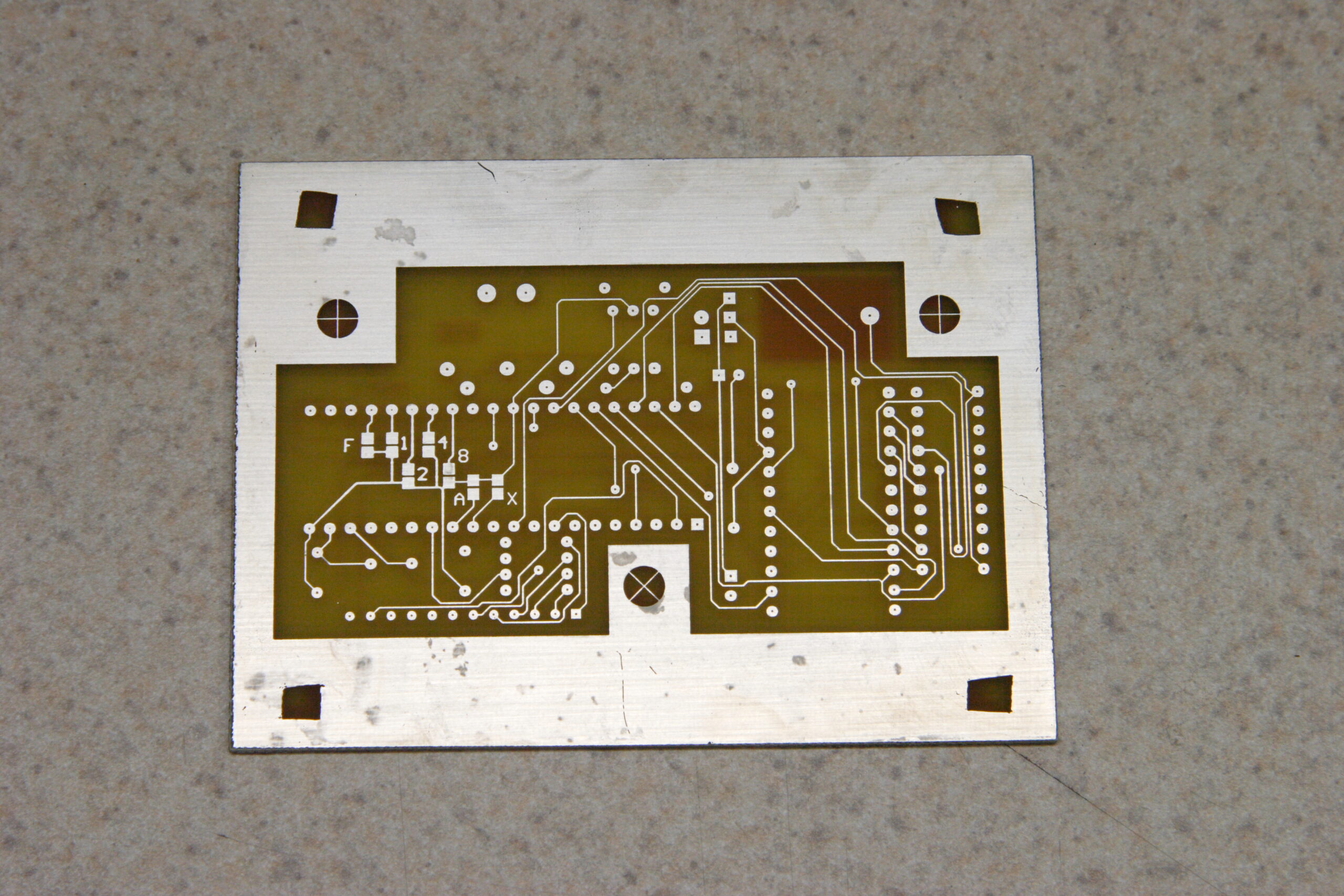
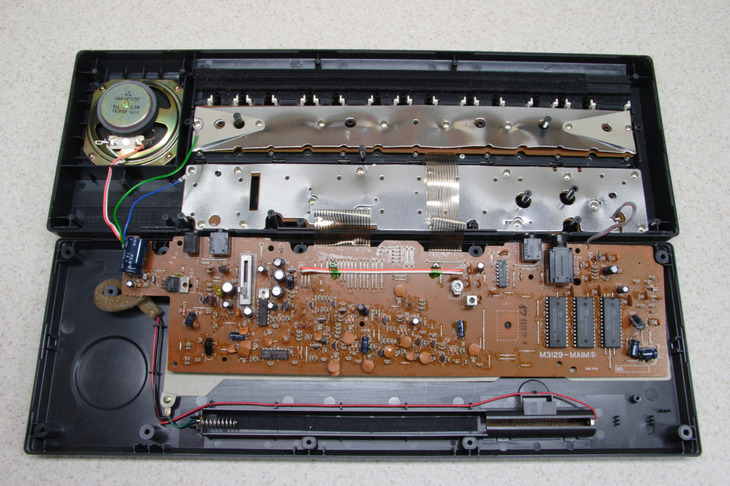
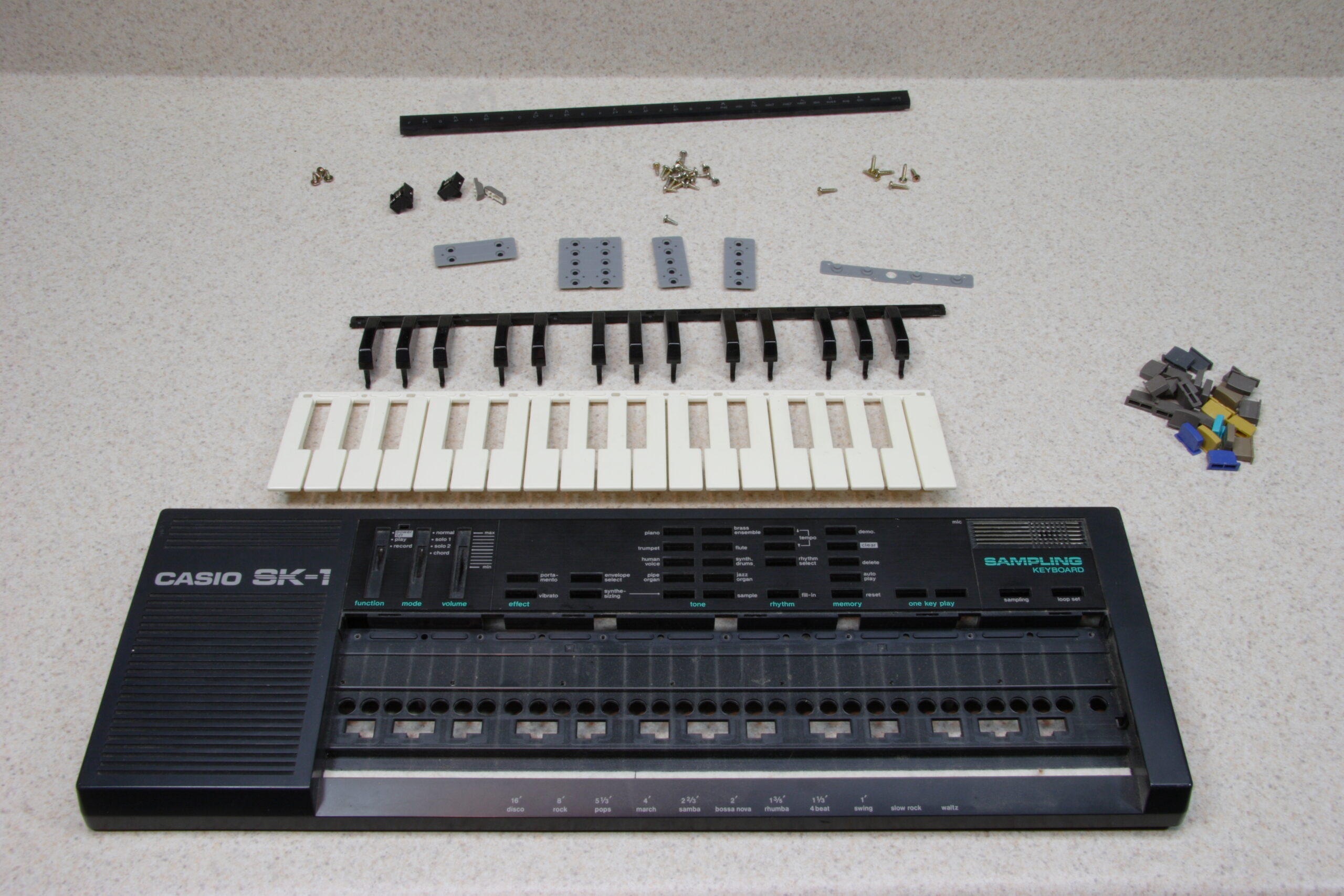
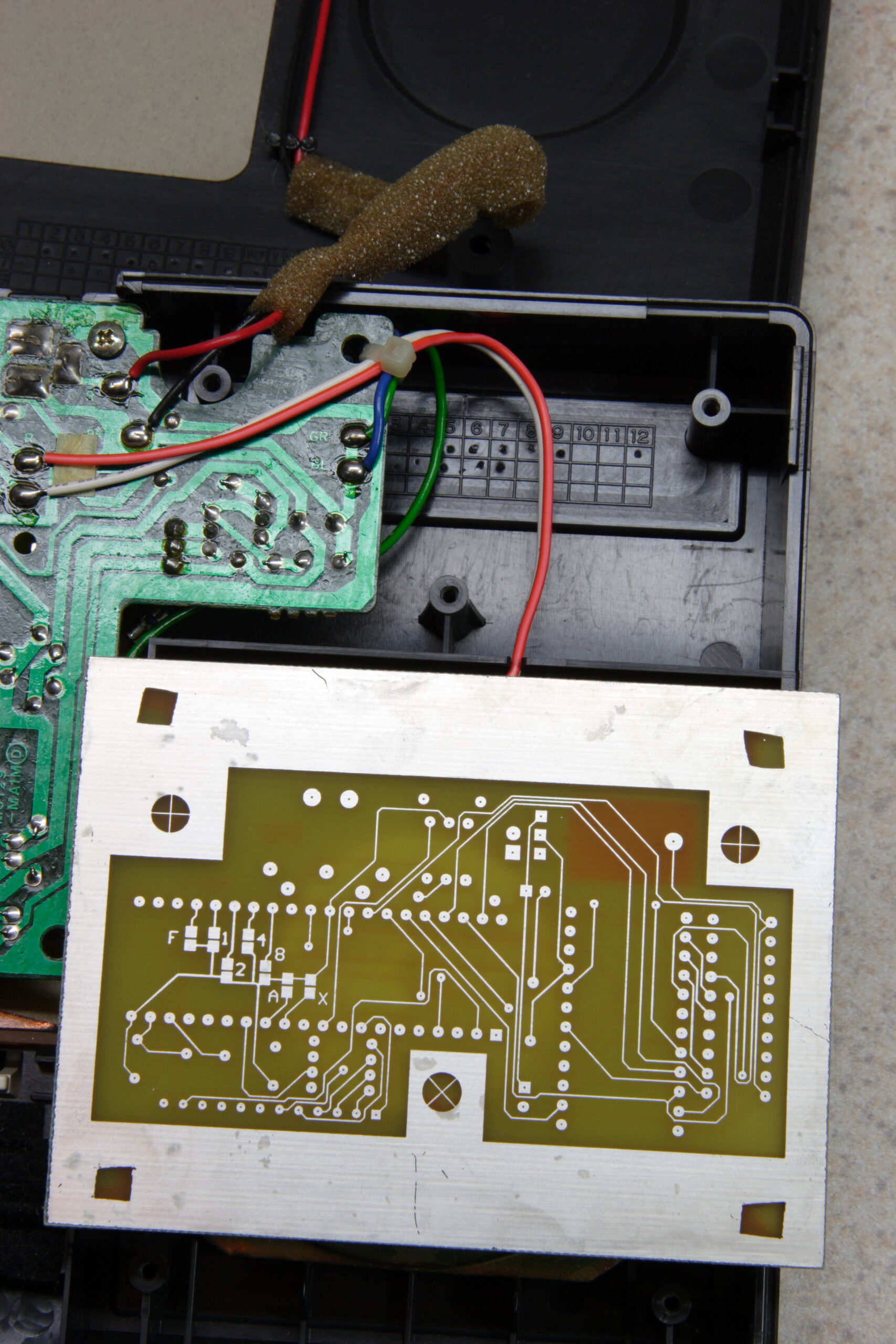
Casio SK-1 MIDI Modification PCB and my opened SK-1.
(Click for more…)

Well, I’ve started the Casio SK-1 MIDI Modification project (photo gallery retired). That is, the one which will add a MIDI input to my SK-1. Since the SK-1 has a rudimentary sampler and the nifty ‘human voice’ patch, along with the fun-to-play-with ‘synthesizing’ section (must remember to read up on this), it could be nice to trigger it remotely.

I’d imagine such a thing would also be useful to anyone with a bent or modified SK-1 (or SK-5, for that matter) too, since those are more likely to be used in a stage-type environment where remotely triggering with patterns would be useful.

Anyway, after making the PCB (and here) on Friday I went ahead and opened up the SK-1 to see how much room I’ll have to work with. While in there I also decided to strip the top panel and give it and all keys and buttons a good cleaning. It actually came apart fairly easily.

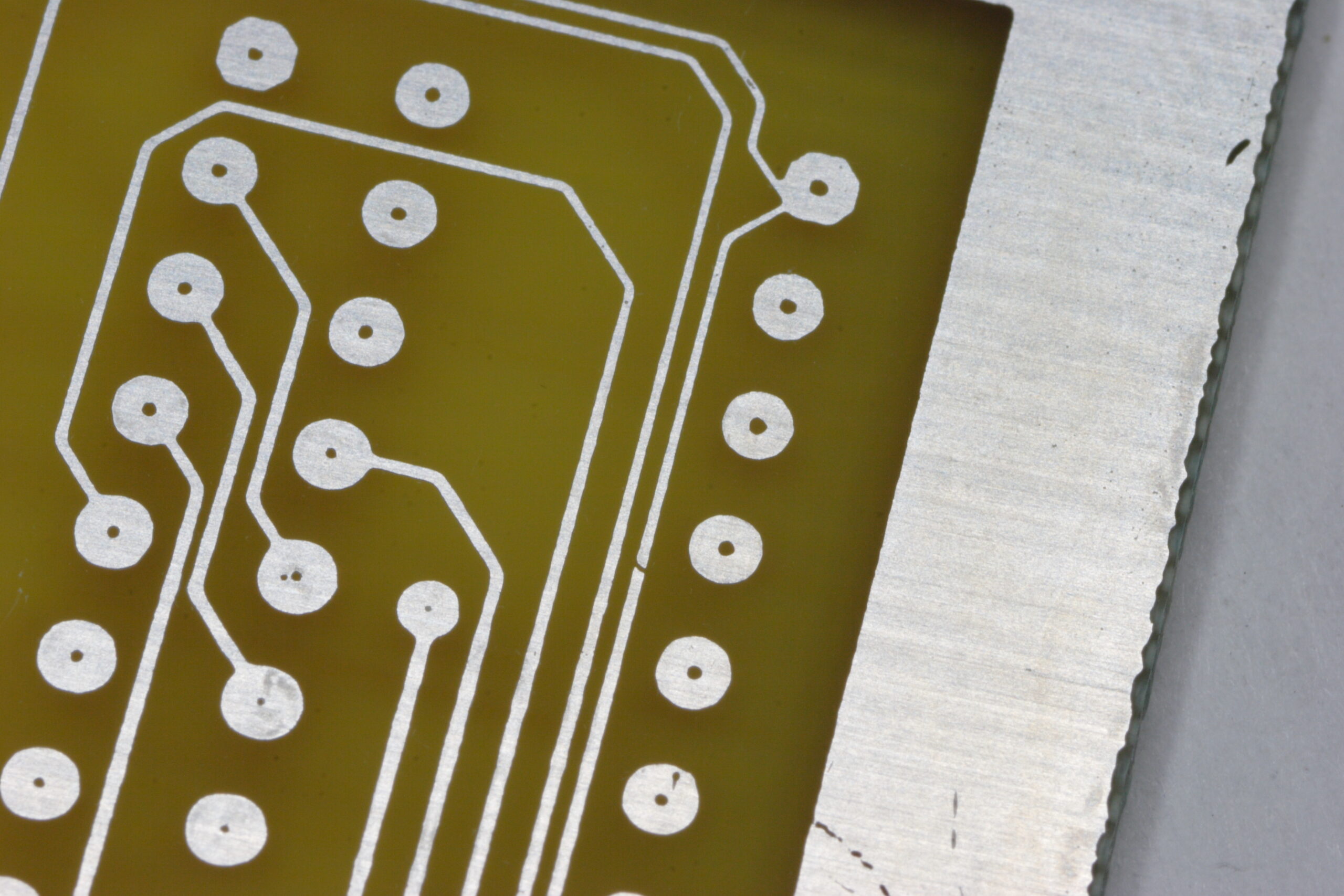
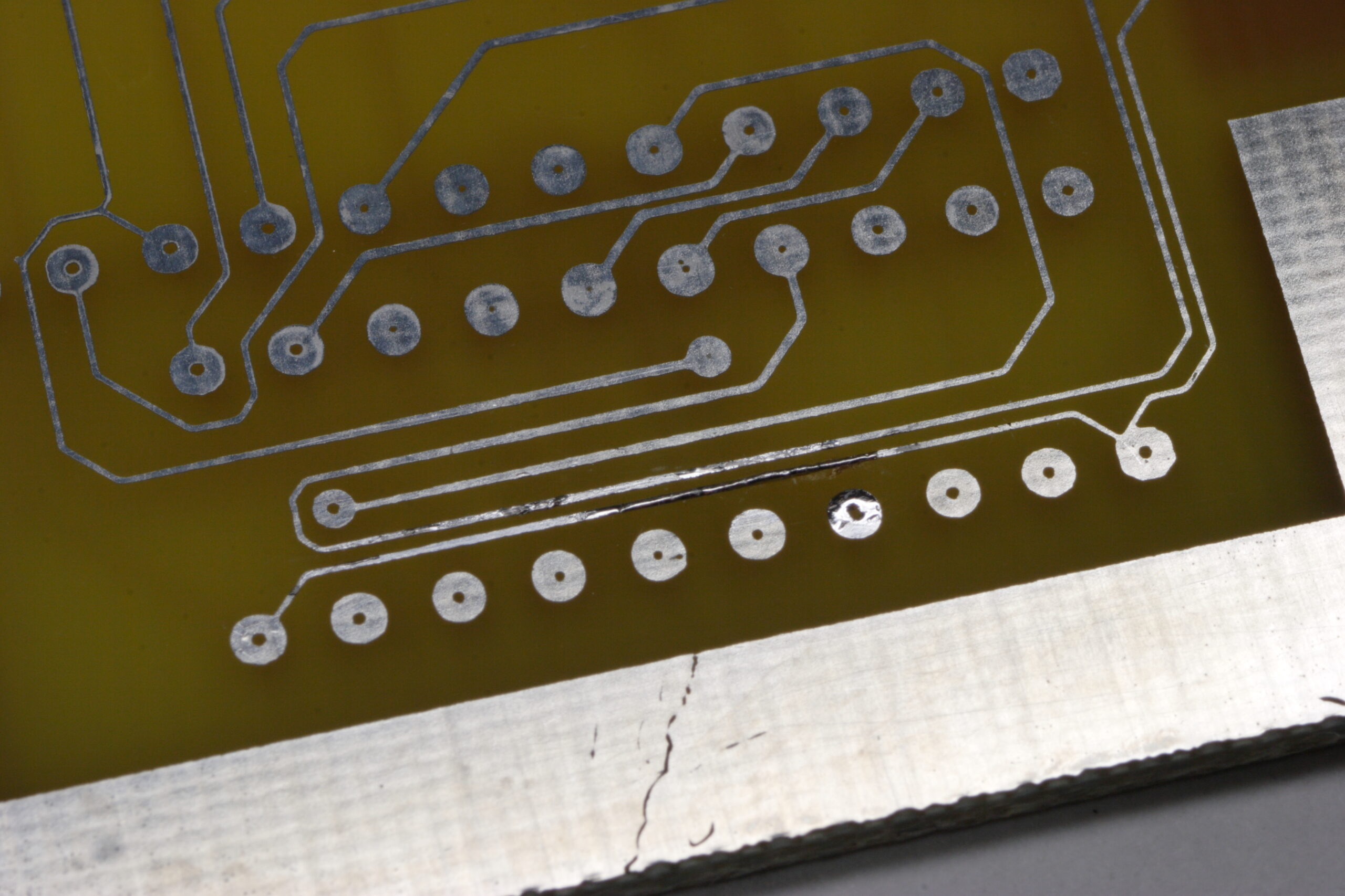
I did run into two problems, though. First, the PCB I made had couple small gaps in some traces where I had inadvertently scratched the photoresist before etching, but those were easily fixed with a wee bit of solder. Secondly, those spots in the tin plating are because I put the board in the plating bath before its precipitate had finished re-dissolving, and I think places where solid chemical sat against the board, those marks were left. Fortunately no pads are affected.

Now I’m just waiting for the set of solid carbide drill bits from eBay which I’ll be using to drill the part holes and vias in the PCB. Oh, and my order from Digi-Key for all the components I didn’t already have. I actually ordered enough parts for two of the adapters. Maybe I’ll etch a second board and make one to sell, if I find someone who wants one.

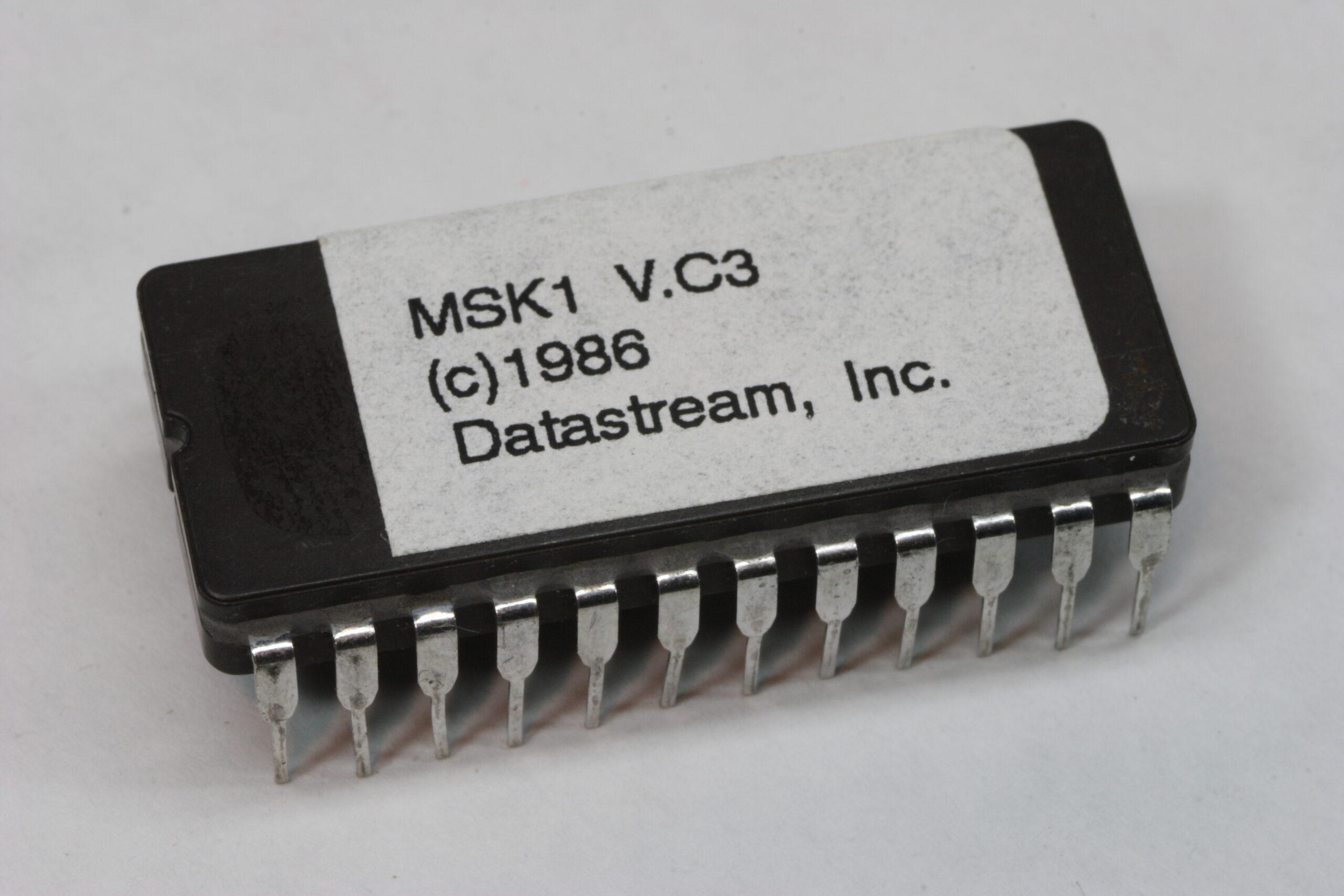
I received the pre-programmed 2732A ROM from Paul Messick yesterday, so I now have the software (yes, 20 year old software!) for running everything. Hopefully by next weekend I’ll have the rest of the needed parts and I can get going on finishing it all up.

One thing I forgot to order from Digi-Key was an Atmel AVR Butterfly so I could play with programming the ATmega169. It’s only $20, so it makes for a good experiment, even if I don’t end up using the controllers in anything. Ah well, one project at a time.

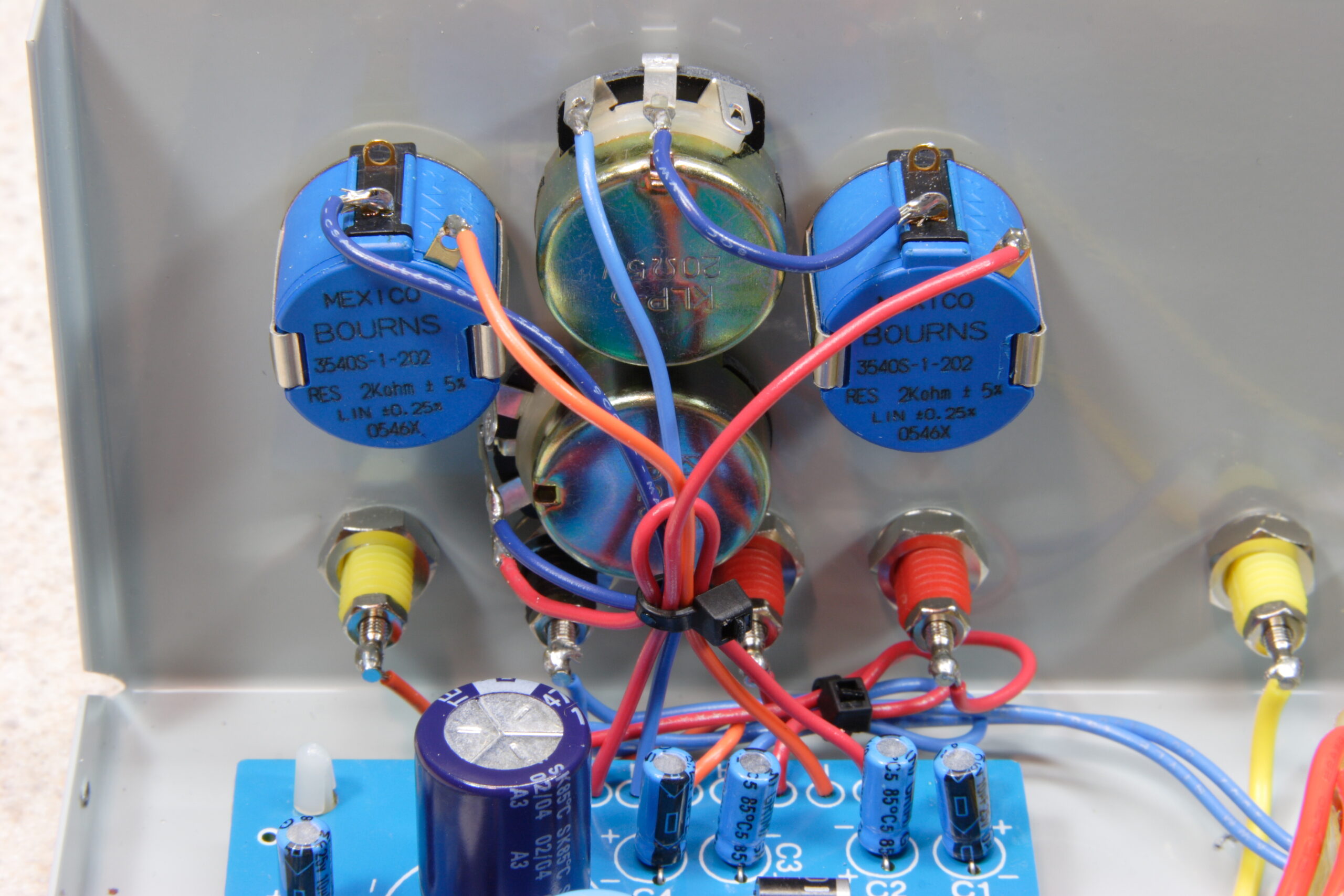
That reminds me… I also ordered some 20Ω wire-wound pots from Mouser (along with a breadboard and other unrelated stuffs) to wire in series with the Bourns 10-turn pots I had previously installed in my Elenco XP-720K (photo gallery retired). While the 10-turns are quite precise, I was having a difficult time nailing thousandths of a volt precision. It was possible, but took some very careful nudging of the knobs.

So, figuring that I have 2KΩ 10-turn pots, one full turn is about 200Ω. That means that the 20Ω ones should add about 10x the resolution, allowing me to hit whatever voltage I want. (I say ‘about’ because a ‘full turn’ is only 300° on a single turn pot whereas it is 360° on the 10-turn ones.) I’m still not completely certain where I will mount them, but for now I think they will probably be fit one above each other between the two current pots with the top one being for the left pot, etc.

Hmm, yeah. That was a lot of babbling about electronics. Don’t worry, I’m done.
electronicsmaking thingsmoved from livejournal

x0x 231 — Complete

[This is cross-posted from here because I am too tired / whatever to write a new post for here right now.]

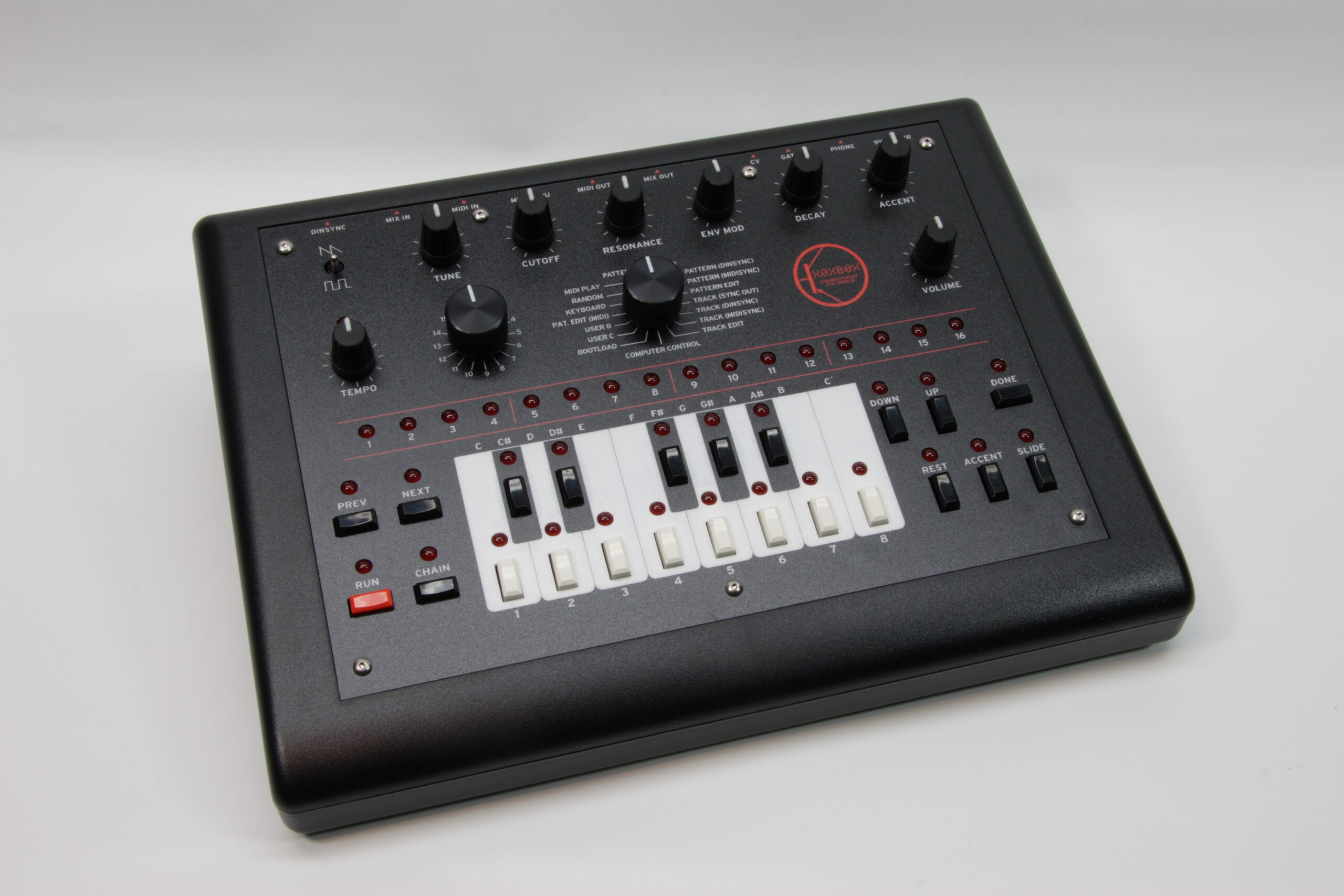
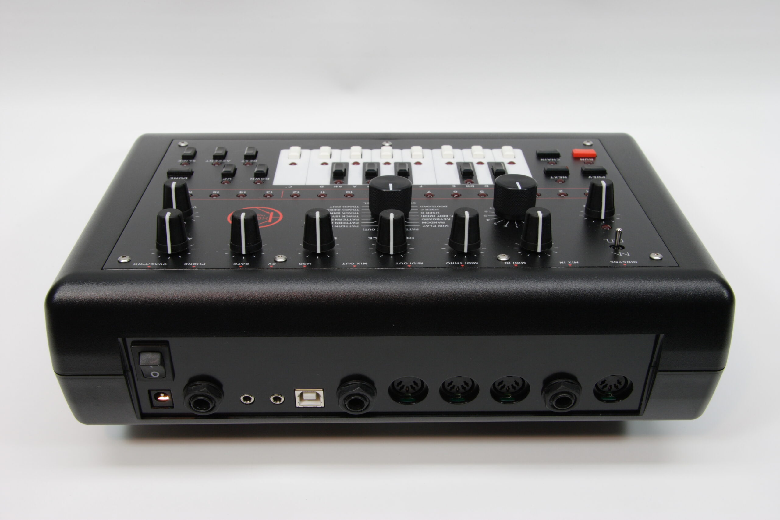
x0x 231, my x0xb0x, is complete. After a fair bit of work and a lot of waiting (mostly for the new artwork to be printed) it’s done.
If you would like to see photos of various phases of my x0xb0x building — including stuff relating to the new artwork — please head on over to my x0xb0x photo gallery (photo gallery retired) and have a look around.

As you can see, I made some new artwork for my x0xb0x. I ordered a few extra pieces, and most of them have been reserved by others, but if you’d like one, email or private message me. I have three pieces left, and as I am making no profit on them, I will not be placing a second order.

The cost for one of the panel overlays is US$41 and includes US Postal Service Priority Mail within the US, and one of the red keycaps you see above.

As far as the rest of my x0xb0x goes, if you’d like to make your x0xb0x like mine, you also need to do the following things:

– Add a power switch.
– Replace R1 with a 200 ohm resistor to make the PS a bit more noisy.
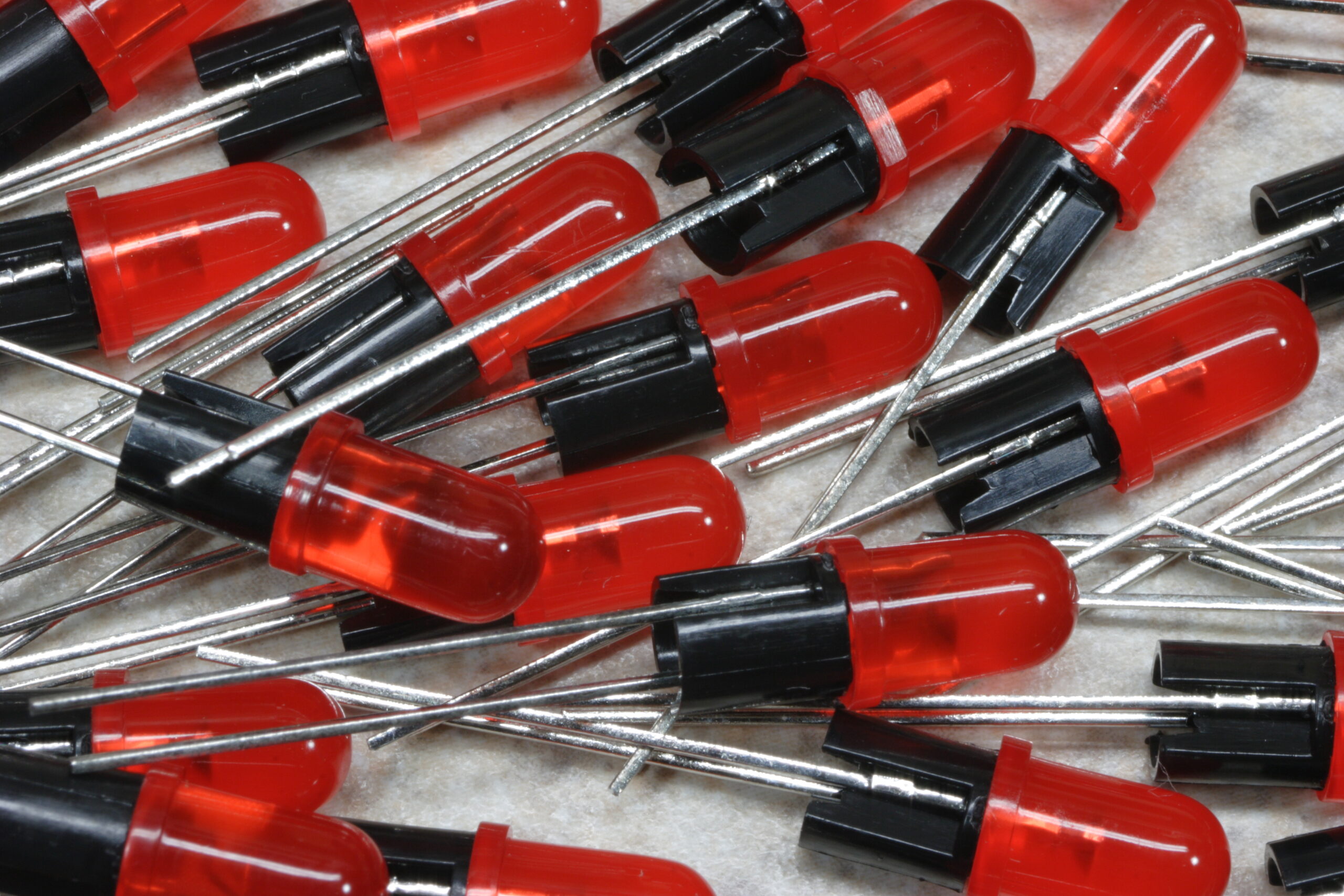
– Replace all LEDs with red diffuse ones. (Digi-Key Part 67-1105-ND)
– Replace all the resistors tied to the LEDs with 820 ohm ones (Mouser Part 291-820-RC)
– Paint the rear panel black.
– Design a new overlay for the front panel and use a red keycap for the RUN key. (As if this one wasn’t obvious…)
– Replace all ‘important’ transistors with ones with ‘high beta’ ones as follows: Q10: 338, Q9: 338, Q8: 349, Q36 & Q38: 335, Q27: 337, Q33: 331, Q1 & Q2 & Q31: 327
– Replace the rotary switch knobs with knurled matte black aluminum ones. (Digi-Key Part 226-4090-ND)

And… That’s all I can remember for now.

I must say, though, I’m glad it’s done.
-Steve

electronicsmaking thingsmoved from livejournal

SQ-909 (or whatever)

Not having a TR-808 or TR-909 or whatever, I’m having a hard time coming up with the concept for a control panel for my step sequencer. The first step is figuring out exactly what buttons and LEDs are wanted / needed. Thus far I’ve got a run button/LED, 16 buttons/LEDs for the various steps, a 16-position BANK knob, a 16-position MODE knob, a 16-position INSTRUMENT knob, and a detented rotary encoder for TEMPO.

Maybe a three-digit seven-segment LED display so tempo can be shown numerically?

electronicsmaking thingsmoved from livejournal

PAiA FatMan Plus


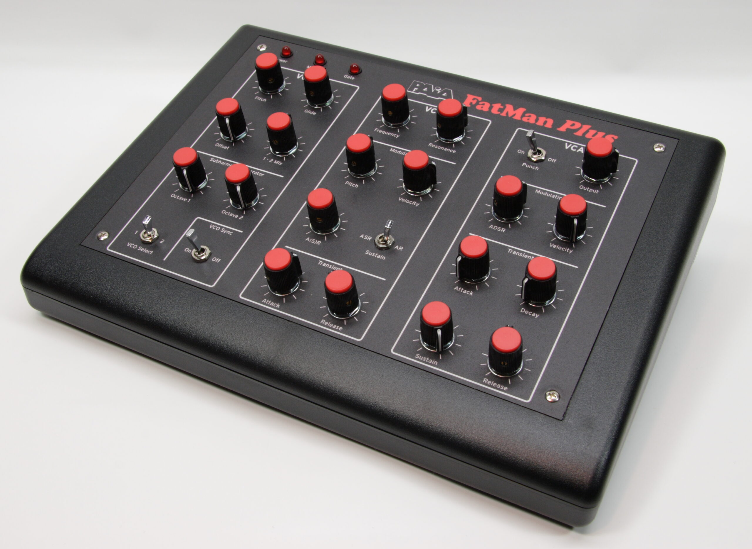
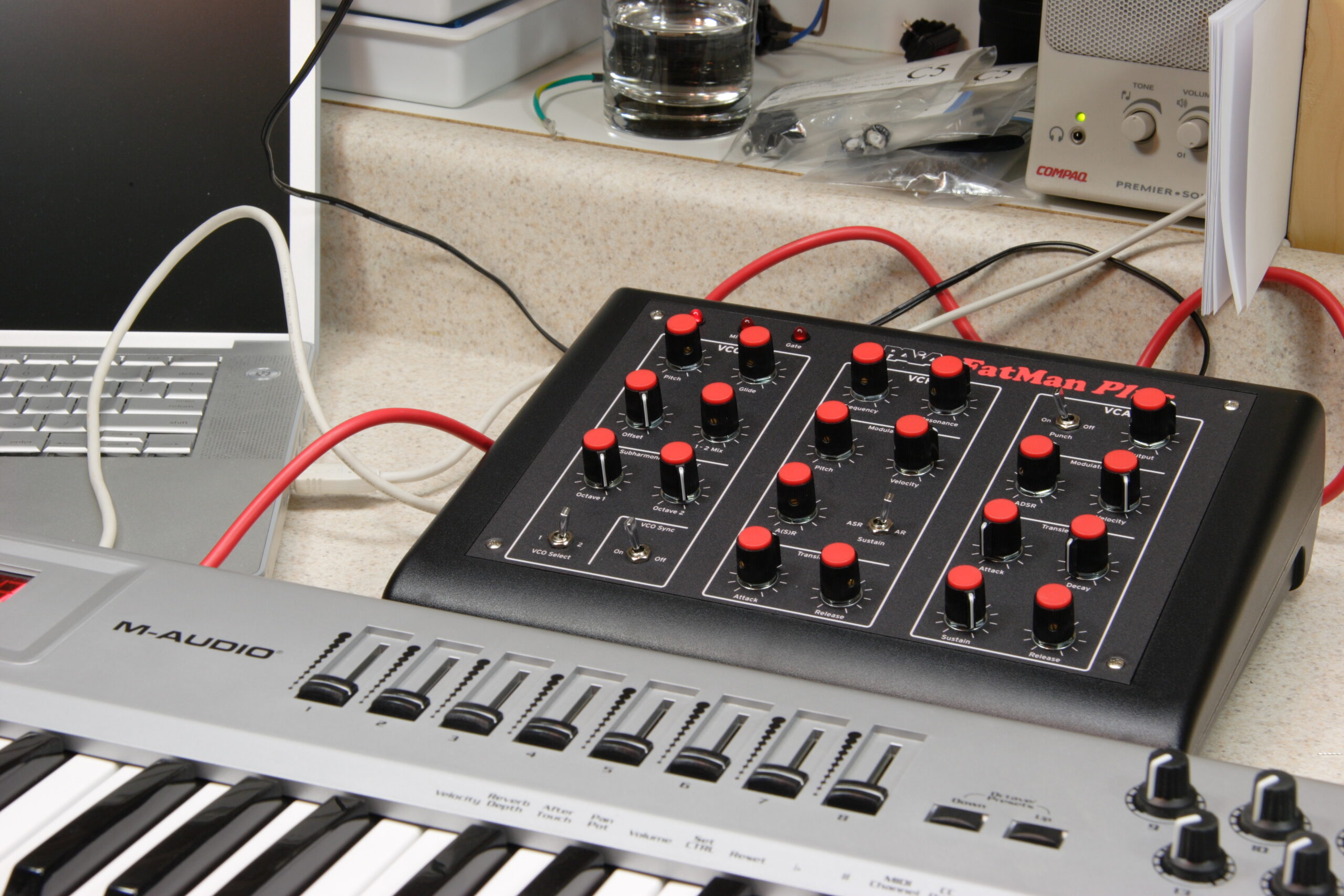
The completed PAiA FatMan Plus
(Click for more…)

Well, there it is. It’s done. No, not the x0xb0x (photo gallery retired), that’s still waiting for the front panel, but the PAiA FatMan Plus.
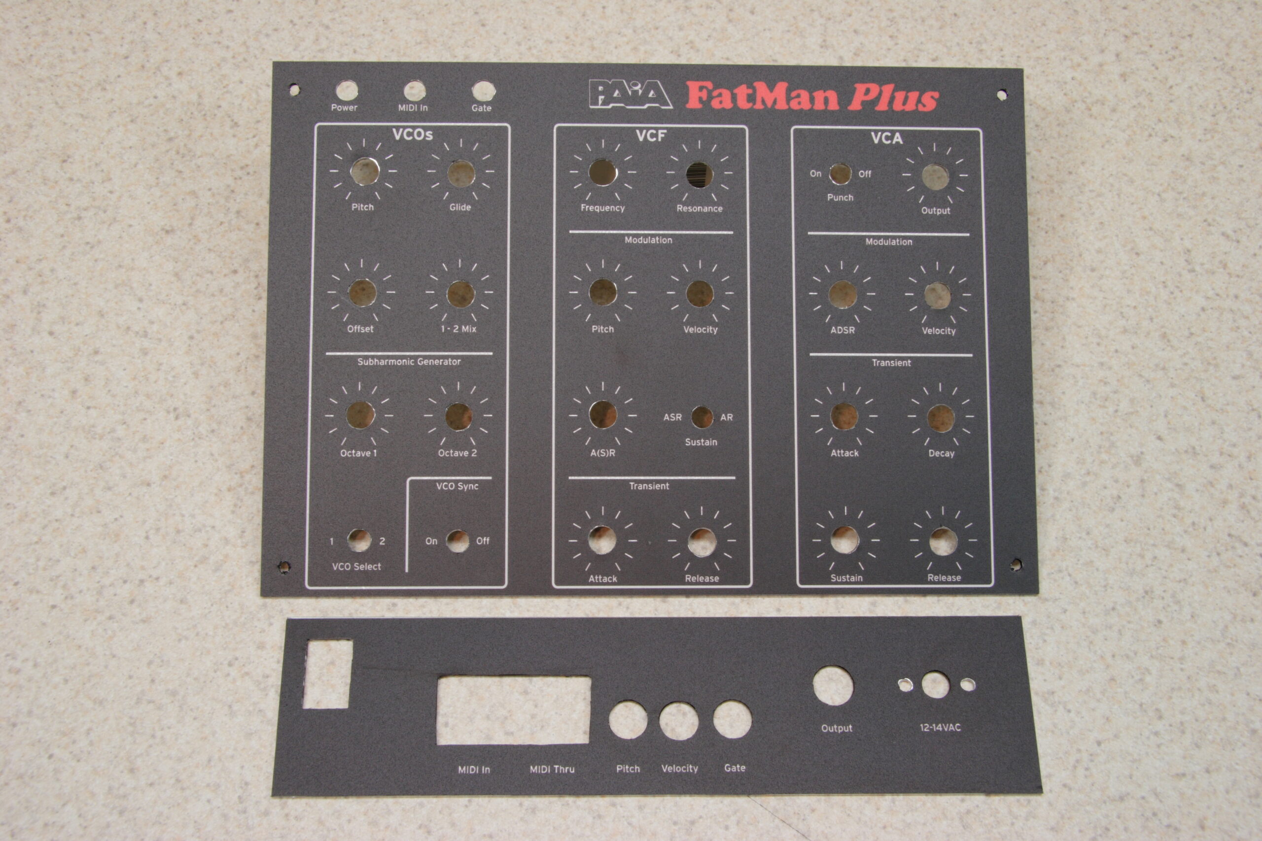
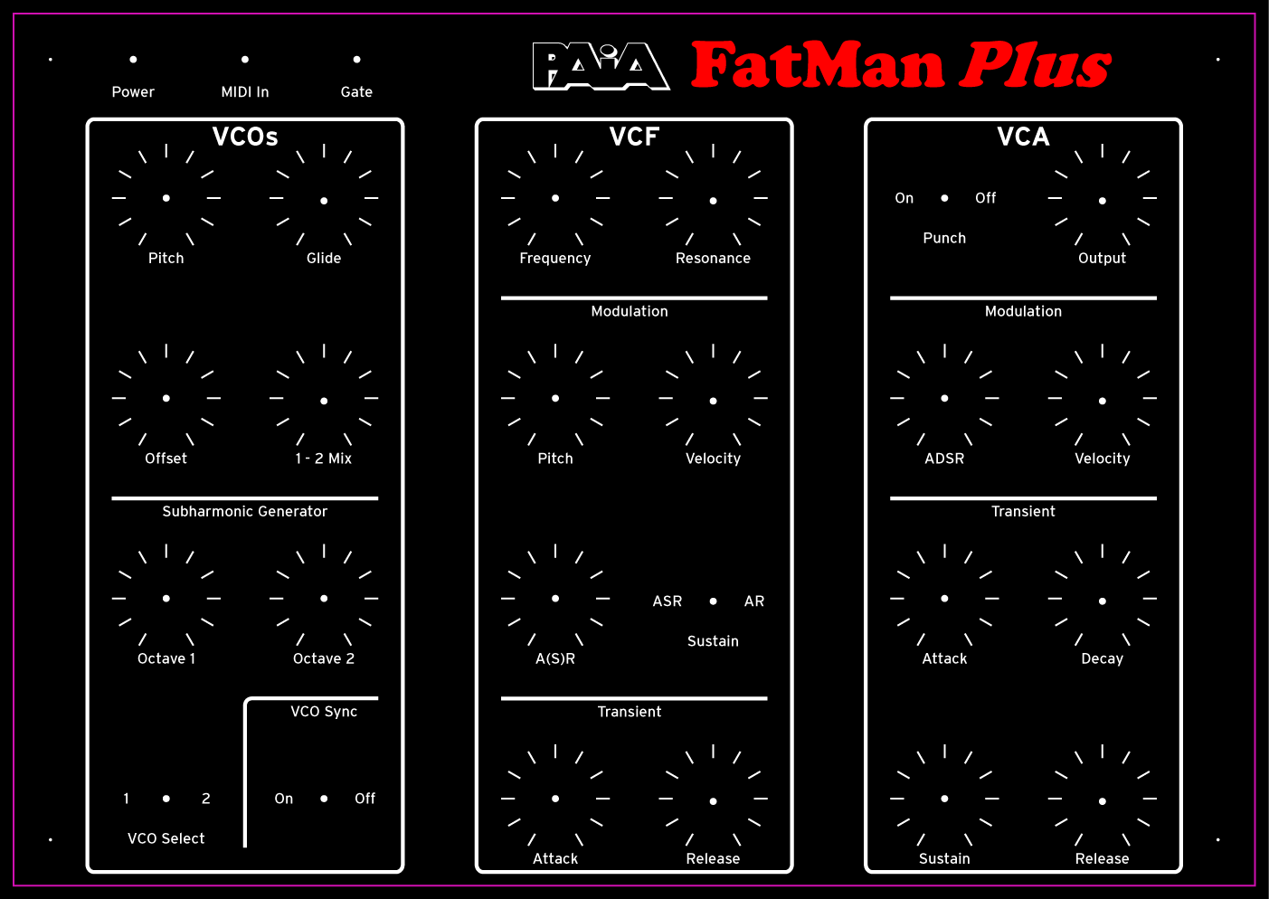
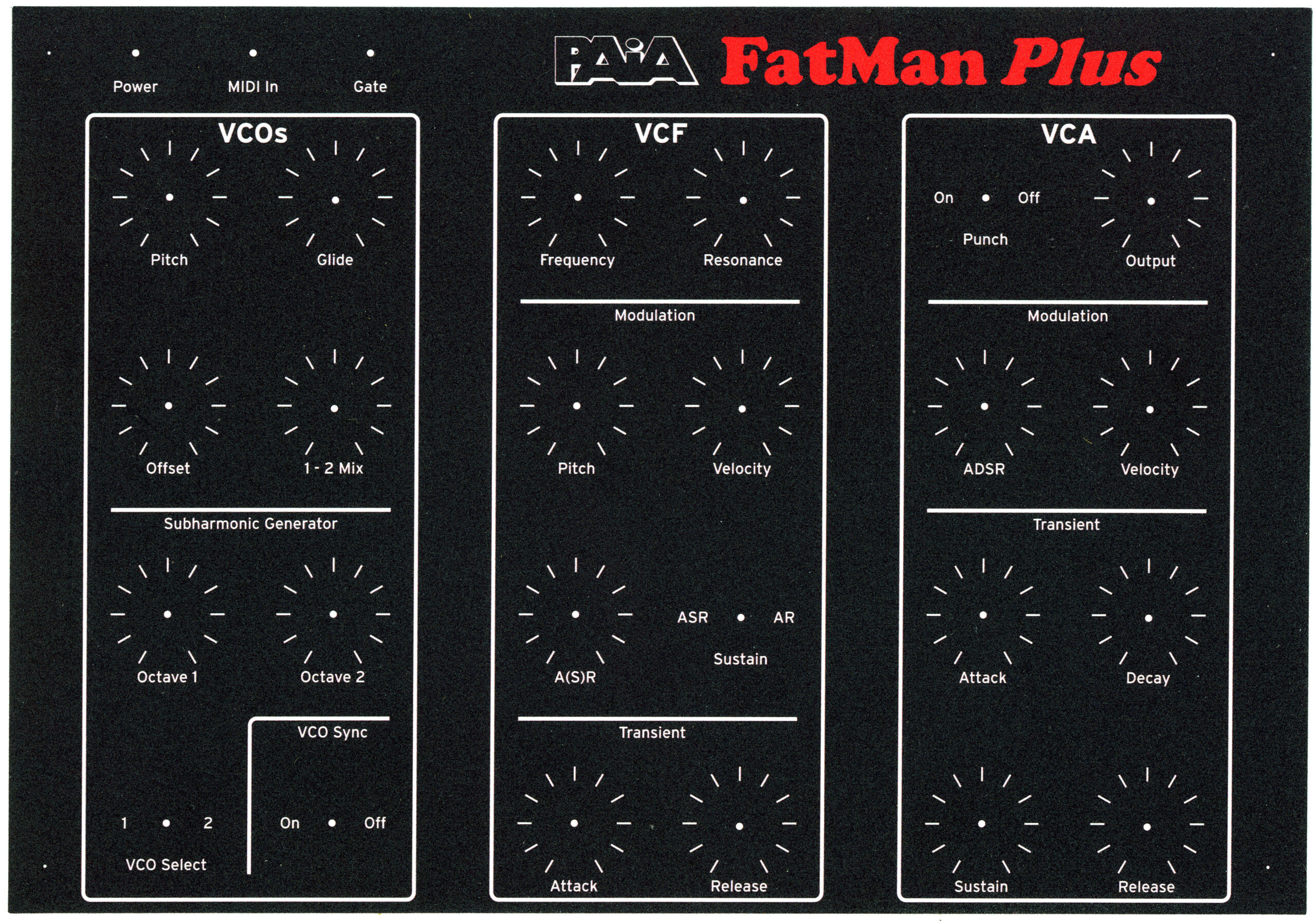
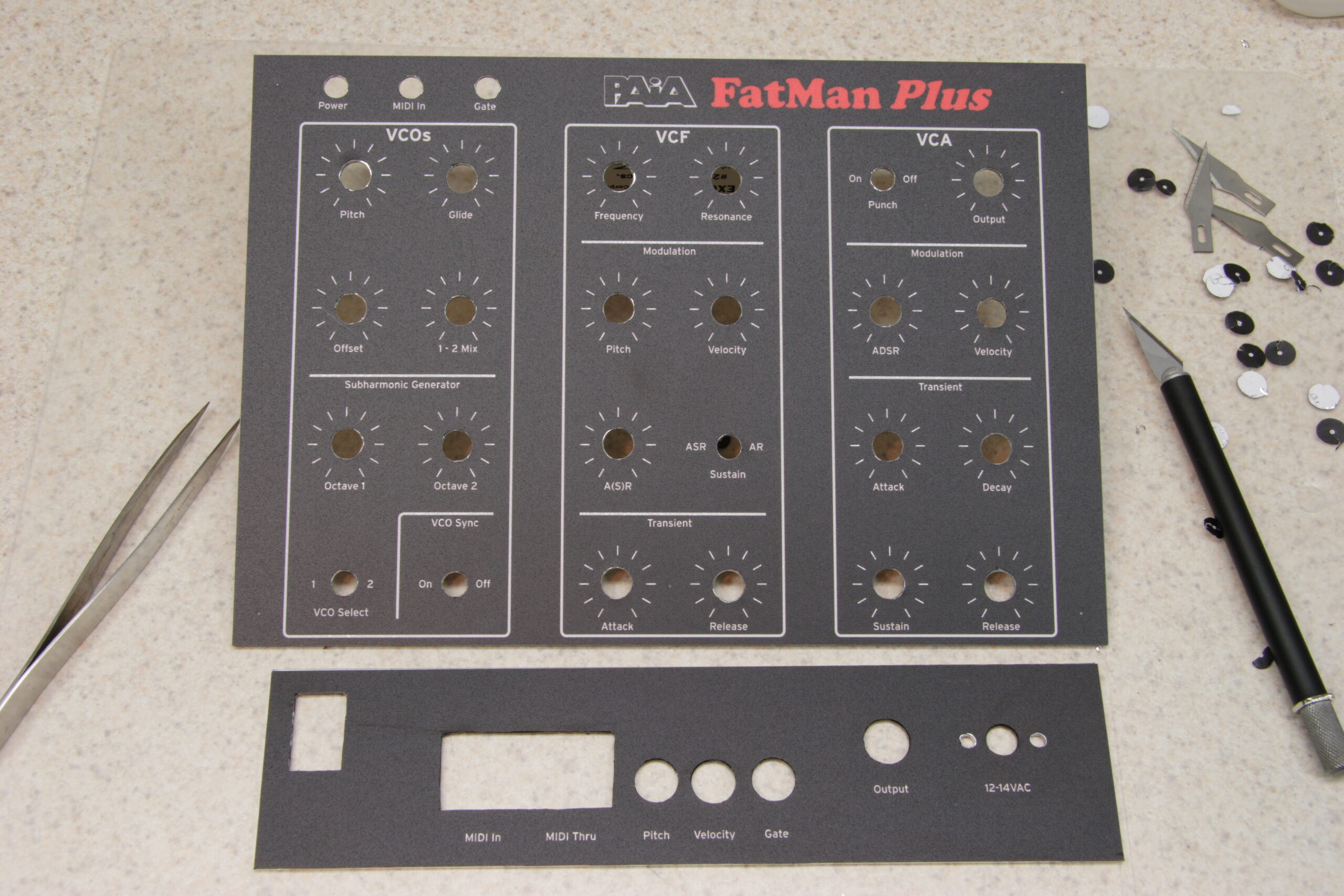
Today the new panel overlays came in from a guy in Ypsilanti named Chris Lowell who owns a sign shop there called Lowell Sign Designs, Inc. I met him on ladyada’s tea party as part of my posts about the < a href="http://www.nuxx.net/gallery/v/stuffivemade/x0xb0x/frontpanel/">redesigned x0xb0x front panels which I’ve been working on. Earlier in the week I sent him my final design for the PAiA FatMan Plus front and rear panels. He gave me a great deal on printing them and they arrived today. They are inkjet printed vinyl with Lexsaver over them, so they don’t look quite the same as the Lexan-only panels from MaverickLabels.com, but they still look good.

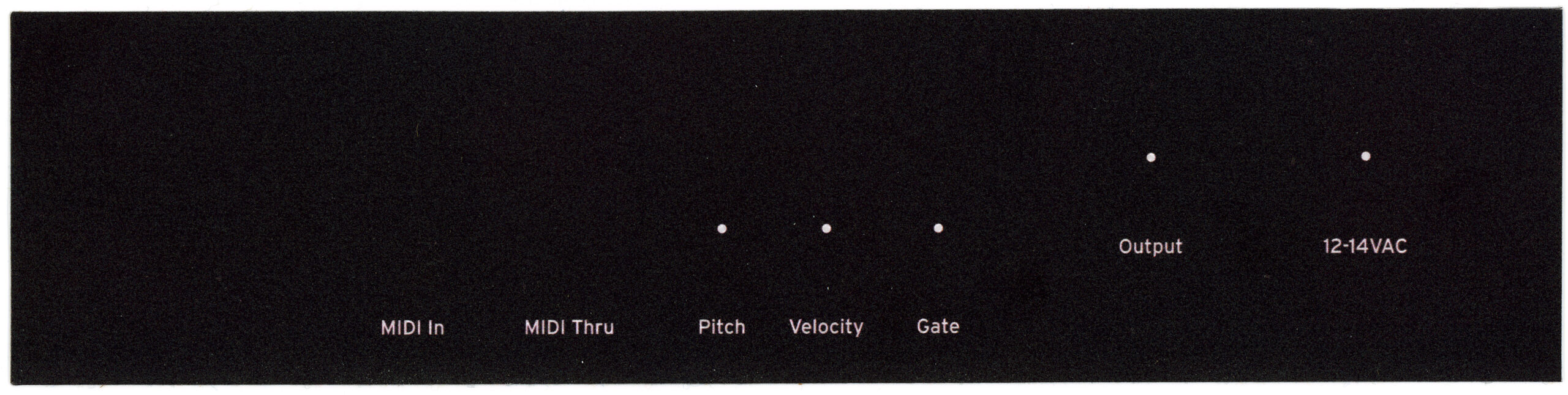
If you are curious, here is a high resolution scan of the front panel, and here is the rear.

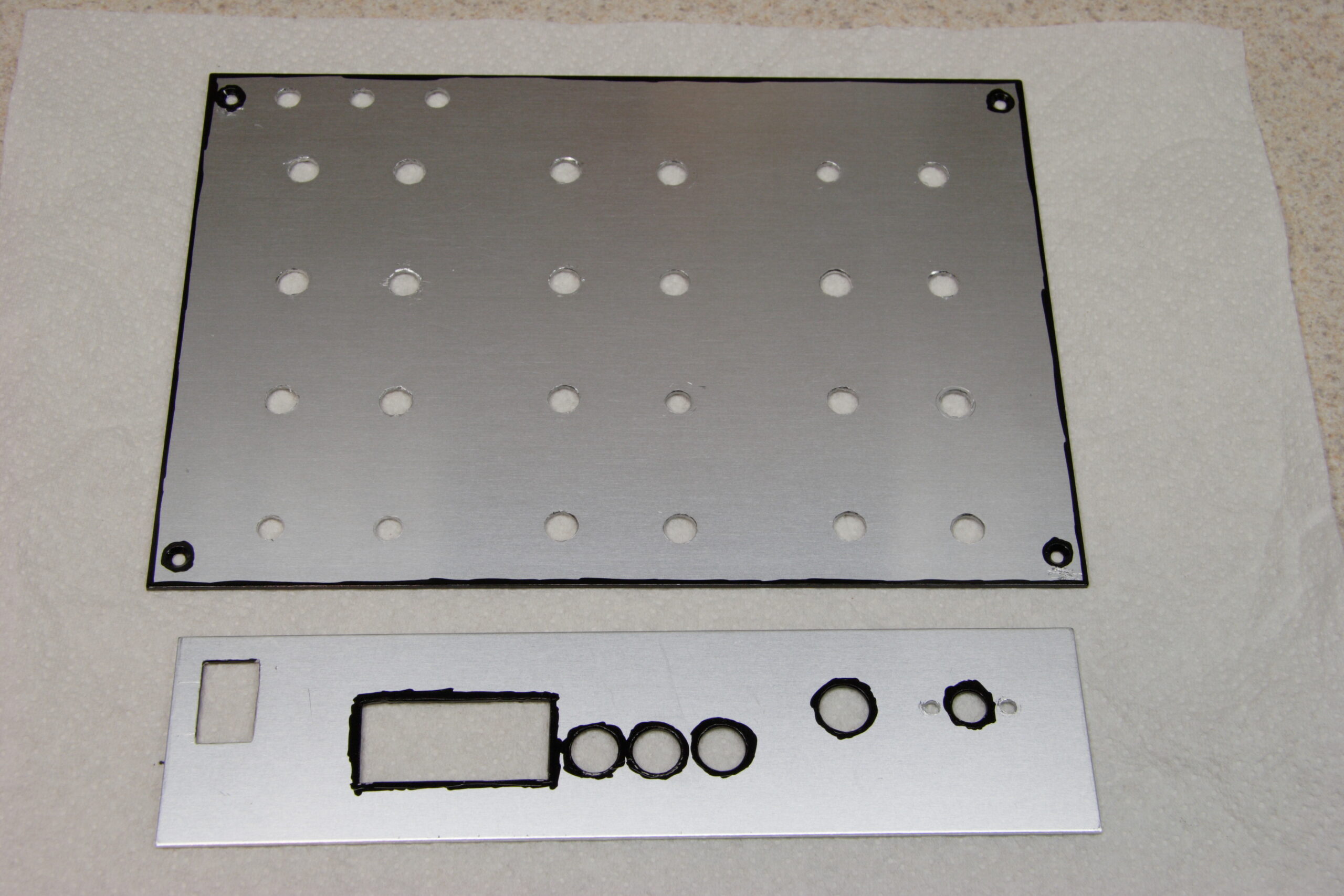
With having a working synth and acceptable artwork, I set to finishing it all up. First I pulled the panels, then I cleaned them up and painted all the edges which could or would be exposed with a nice black paint pen. Next I applied both overlays and cut out all the holes. The holes for through-hole parts didn’t need to be perfect, so I just generally followed the metal at the edge. For the countersunk holes for the corner screws I didn’t cut all the way to the edge, that way the fit around the hole would be nice. The rear holes were a bit tricky, but I think I managed.
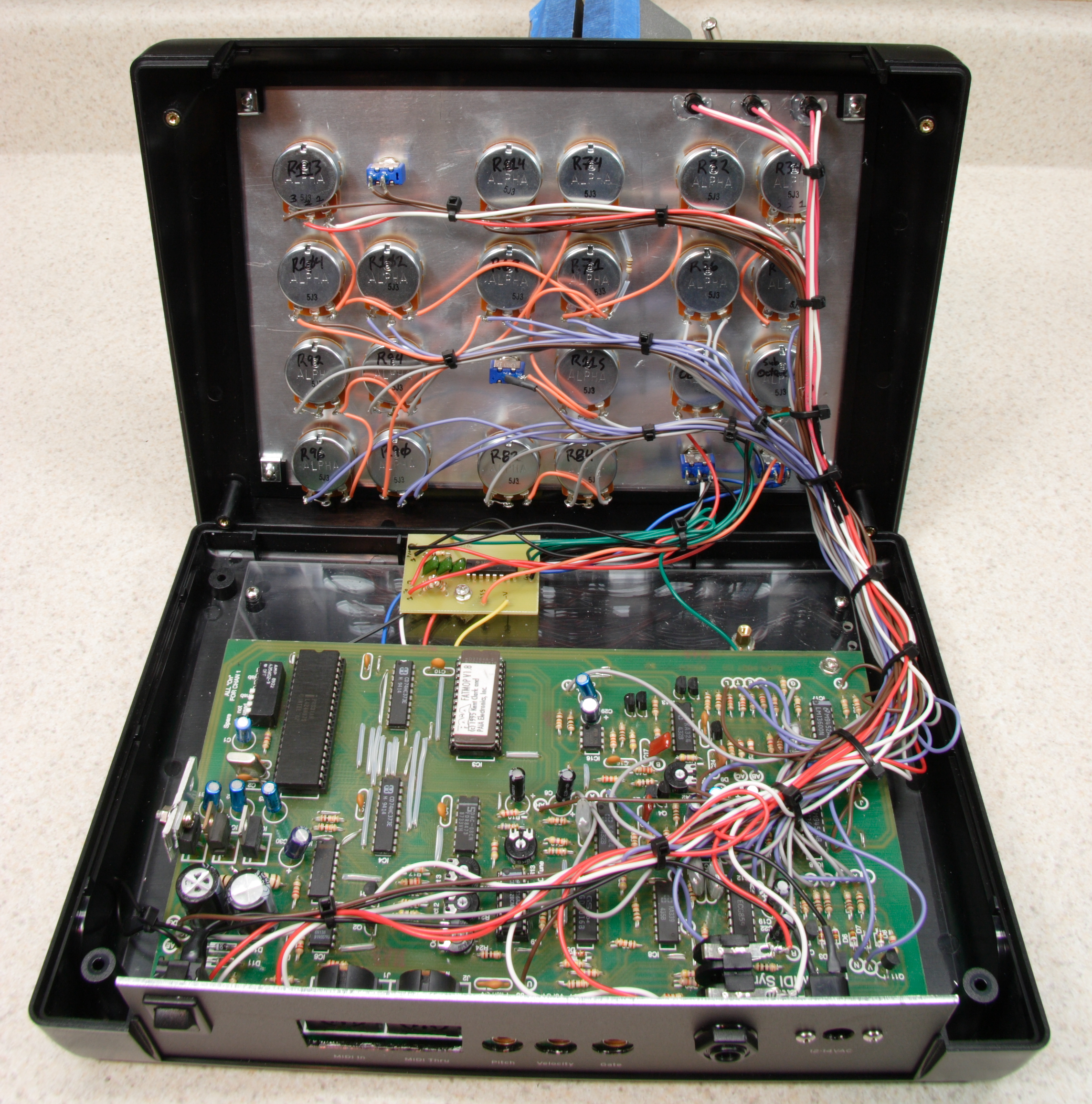
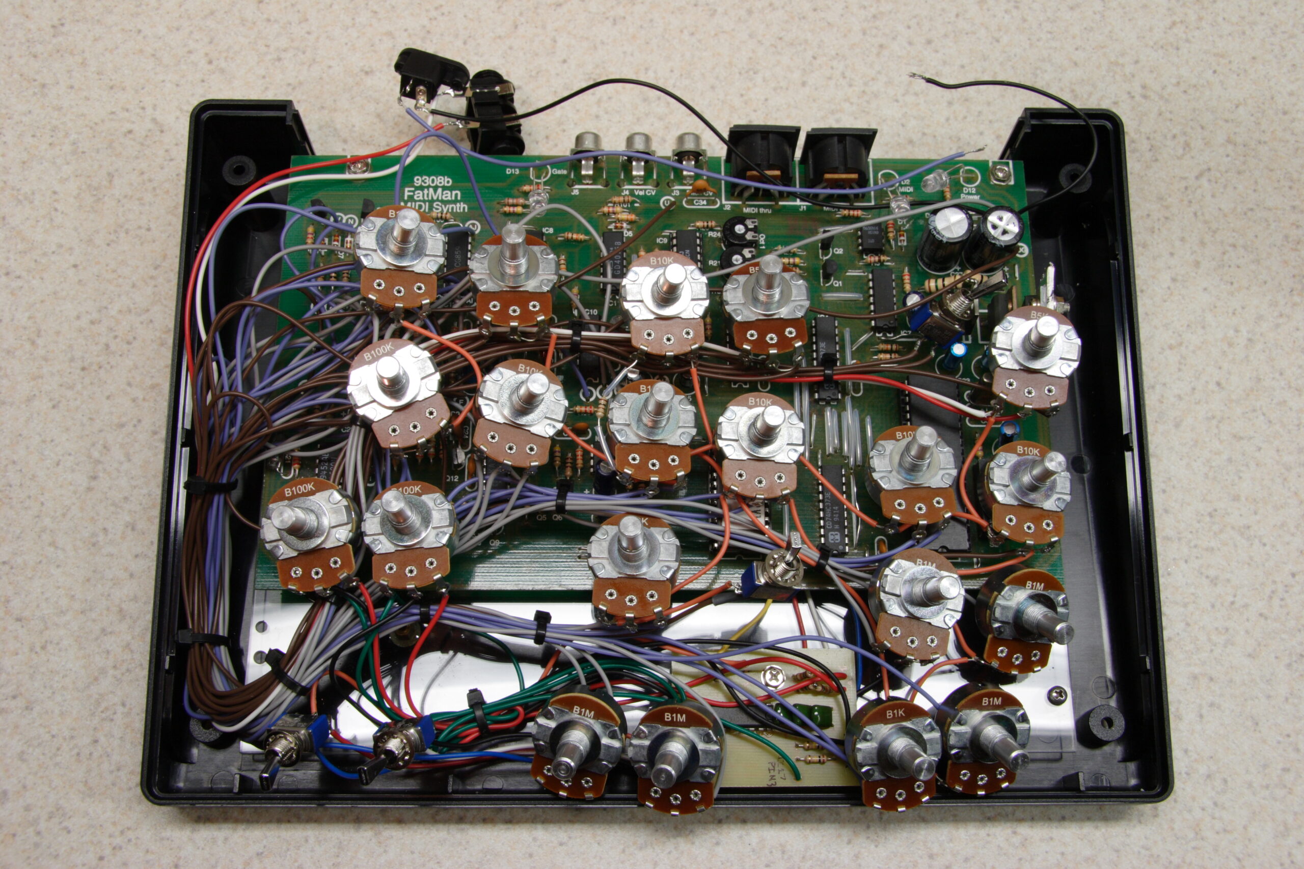
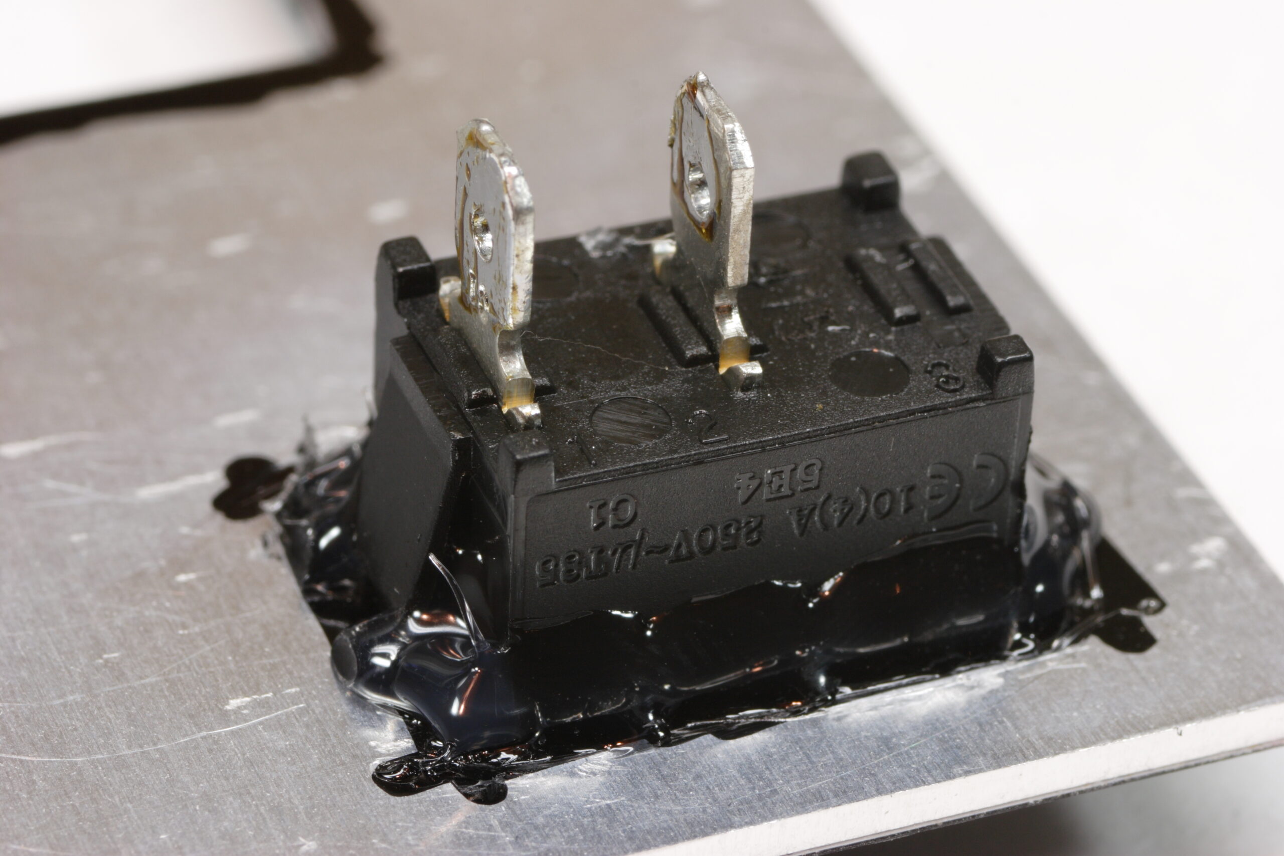
Then it was time to get on with the final assembly. I refitted the rear power switch to ensure it was solidly mounted, mounted and connected the LEDs, reinstalled everything else in the rear panel, fitted the rear panel, bundled all the wires so it would fit nicely.

After screwing the case shut for (hopefully) the last time, I gave it one final test with a MIDI keyboard before calling it finished.

And now? It’s done*.

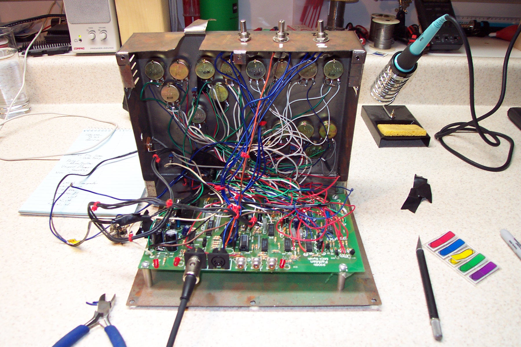
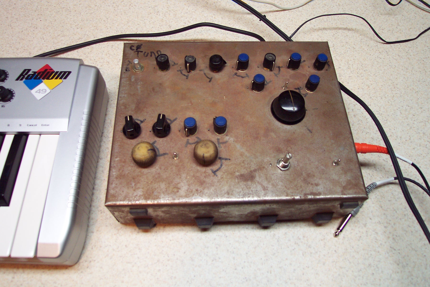
So, what was this mess in this case (yes, I like the rusty metal look too, it was just unusable and non-functioning) a few weeks ago is now this not-mess in this enclosure. Thanks to the Hard Sync and Subharmonic Generator additions, it’s capable of producing even more interesting sounds, too.

If you are interested, there are more photos of my PAiA FatMan Plus available here (photo gallery retired).

And now, with this done, I go to bed.

Goodnight.

* There are a few more tweaks I may make, like replacing the optoisolator (it may be causing me some problems responding to very frequent MIDI commands) and possibly some range adjustments, but those will come later, if ever.

electronicsmaking thingsmoved from livejournal

Detroit Band Saw

Wow. So I just called Detroit Band Saw and told them what I needed. That is, a 67-1/2″ bandsaw blade for cutting metal. Well, I’ve now got the appropriate blade on order, at a really nice price. They offer two types of material, carbon steel or a flexible alloy with M42 cobalt teeth, 1/2″ wide. The prices for the blades are $9.69 and $23.60, respectively. I went with the more expensive one because it’ll work for stainless steel and other such things, and the price… Well… I think that’s just great. They are going to make it up today and sent right out.

This makes me really happy. :)

All they do is custom make bandsaw blades and they will ship them, so I’d probably have to recommend them to whoever else needs such a blade. Prices are the same as all the big box stores, and they are *exactly* what one needs.

acquired thingsmaking thingsmoved from livejournal

Bandsaw + Labels

Well, the new bandsaw is much nicer. I just need to find a blade for it. :\ Well, a 18tpi or so blade so I can properly cut PCBs and such.

While outside of Home Depot I got a call from MaverickLabels.com. I spoke with someone there named Scott who didn’t know the complete history to my problem, but was working on getting the labels printed. He wanted to ship 8 of the labels to me tonight, and another 4 tomorrow, just so I’d have them in the morning. I declined and said that he can ship them all in a single batch, and that I’m less concerned about time and more about just getting them right.

That said, I’m starting to wonder if they aren’t up to the task of printing these. Hopefully I’ll know more tomorrow or Monday. < sigh > I just want the damn things right… I guess, worst case, I just use the first batch with the missing artwork.

Blah.

UPDATE: Gur. I seem to do things like this a lot. That is, buy a bandsaw with a non-standard blade size. :\

acquired thingsmaking thingsmoved from livejournal