PICs, SIDbox, and Mistakes
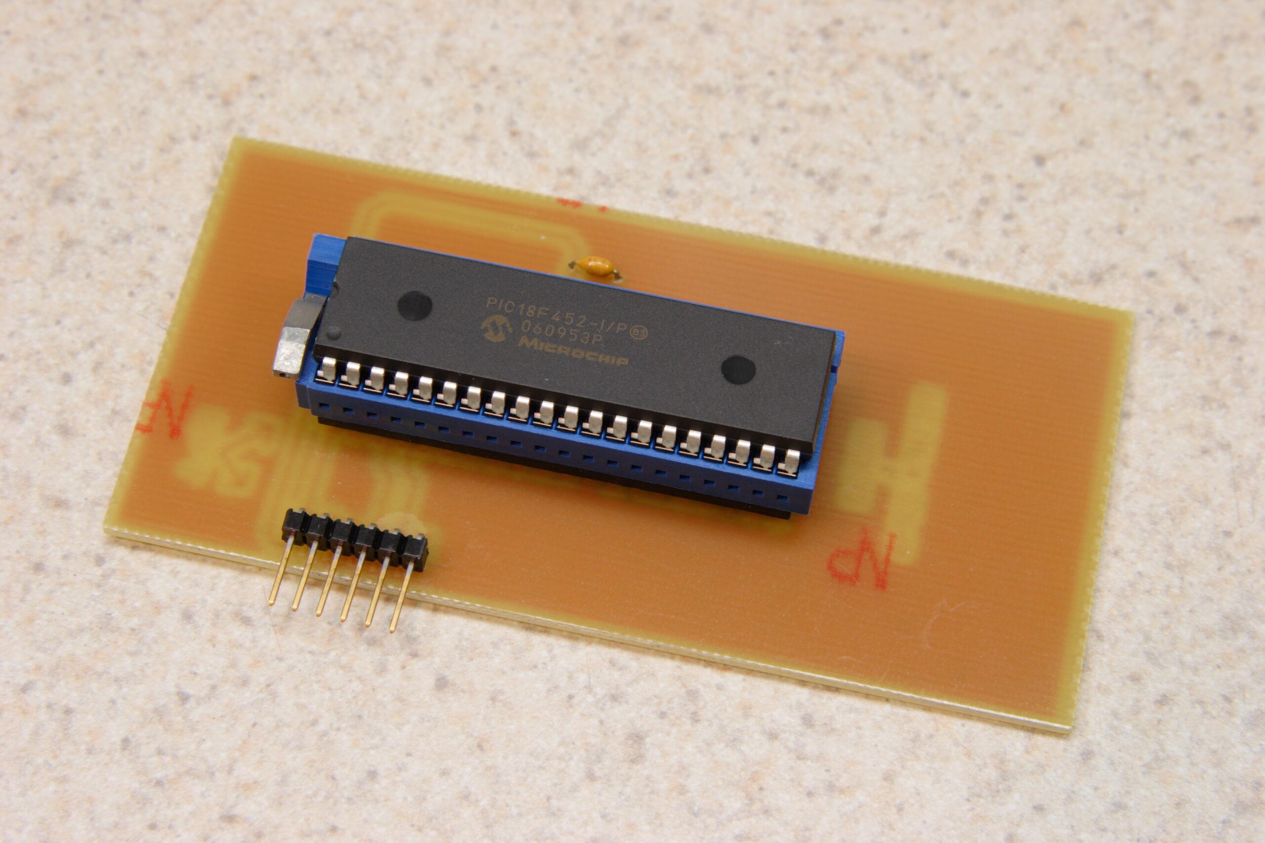
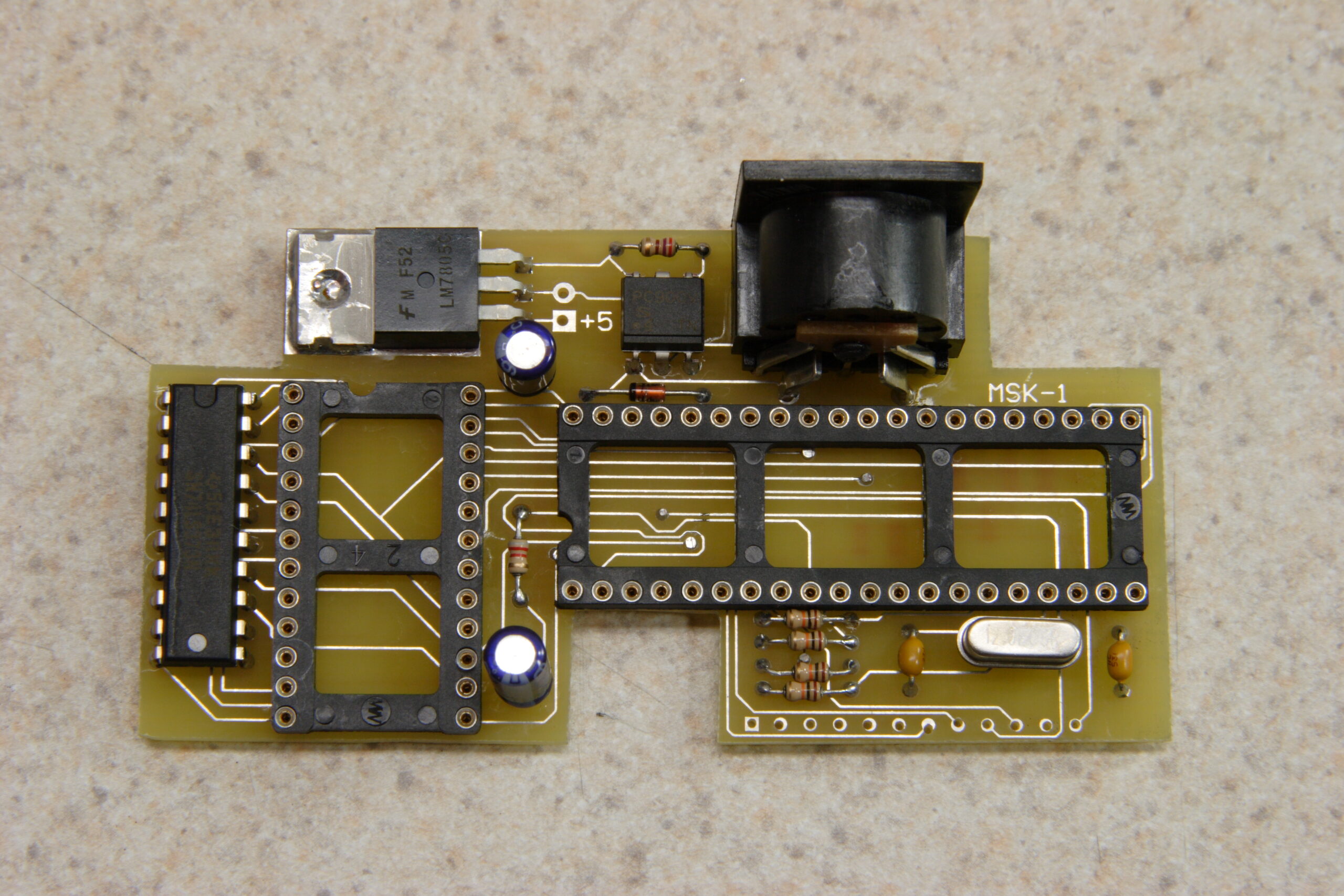
Microchip PICkit2 to DIP40 Adapter
Okay, so this post is going to contain lots of babbeling as I try to get my thoughts together…
First off, it seems that I made a bit of a mistake with this SIDbox I’m working on. The mistake stems from my thinking that the PIC18F452 is part of the PIC18F4520 and can thereby be programmed with the PICkit2 which I have. I was wrong.
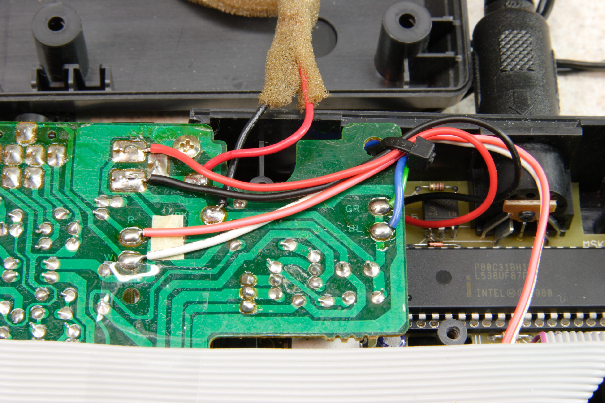
Based on this faulty thinking, I both built the PICkit2 to DIP40 adapter (photo gallery retired) which you can see above and included support for using this programmer in the SIDbox (photo gallery retired) I hope to build.
So now I’ve got some hardware / connectors on the SIDbox PCB which are pretty much useless as the device would normally work.
At this point I have two choices…
The first is to build a new PIC programmer (probably connected to a serial port) which will properly flash the PIC18F452 using the 1×6 pin header found on the DIP40 adapter (photo gallery retired) and the SIDbox (photo gallery retired) and use the existing hardware layout and order the PCBs.
The second option is to use a newer PIC, the PIC18F4620, on the SIDbox instead. This has the advantage of being completely compatible with my programmer and thusly the adapter and the programming hardware on the SIDbox board. However, there appears to be a bug in the hardware of the PIC18F4620. The end result of this bug is that one can’t use a MIDI output directly from the chip. So, I’ll have to add some additional hardware to provide MIDI output. On the upside, this extra hardware (the MIDIbox IIC MIDI module) provides for MIDI LEDs, making part of my existing design redundant. That means some board space is freed up for the new hardware.
So, at this point I’m not completely certain what to do, but based on the responses I am getting to this post at the MIDIbox forums, I think the second option is going to be the best one. In fact, I’m going to change the schematic and start laying out the board for this now. Just in case I decide that’s the best way to go.


