Printed Crap Board
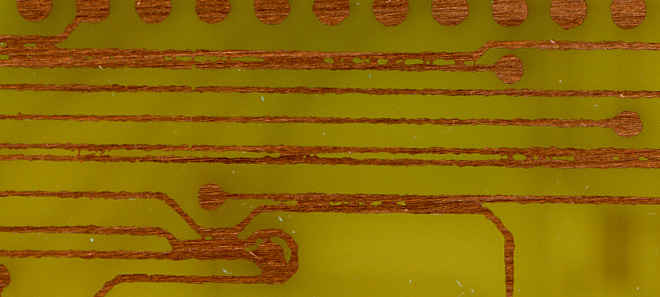
The traces are nowhere near as clear as they should be.
So, yeah. Tonight I tried to make the printed circuit board detailed in this PDF on this page for making it possible to trigger my Casio SK-1 via MIDI.
Well, I learned two lessons in doing this…
First, my technique for registering the two sides on a double-sided PCB appears to be successful.
Second, my method of laser printing the mask on vellum and exposing to fluorescent light for 10 minutes isn’t good enough for fine lines. As you can see above, something went awry and the photo resist between the lines wasn’t exposed to enough light.
I think I’m going to try an experiment with various levels of detail and a smaller single-sided PCB with a piece of laser printer transparency, just to see how well this method will work. I don’t think it’ll work out so well, but it can’t hurt to try…
If this doesn’t work, I guess I’ll have to order some special paper just for doing this kind of thing. That won’t be cheap…
Well, at least I’ve got a few more unexposed boards to play with.
Oddly enough you just discovered EXACTLY the same problem I had when trying to teach myself silkscreen printing. I even invested in a unflitered Black Light light box, which helped but still no good for fineline.
The next step I took was to use transparancies and print with the LJ on FULL density. Then make sure you expose with the image on the material. Exposing thru the film was still enough to blurr the edges.
The problem appears to mostly be in the light source. Fluorscent lights send out scattered light rays. You need a light source that gives out directional rays. This is the same method used in printing photography. We use condensor or dicro light source in increase contrast and sharpness and neon for softness. But sadly our darkroom sources are only about 1000watts sort of what is needed for silk screen exposure.
I’d be very interested in learning what you find. Maybe we can also get together someday as you would be welcome to try it on silkscreen if you’d like.
I’ve been printing the mask backwards, so that the toner side is against the media being exposed. Then there is a piece of glass set over the top to (hopefully) smooth it a bit more.
I’m thinking that my problem more has to do with not enough contrast between the clear and opaque parts of the mask.
Last night I noticed something interesting… At a few points on the mask, over the scrap parts of the board, I had holes cut through so that I could tape down the mask to each side of the board. This was taped using standard, crystal clear tape.
Well, when developing the board, I found that the parts which had the clear tape over them (and thusly received a *lot*) of light developed very, very quickly, while the rest of the board took tens of minutes.
Based on this, I’m thinking that if I use transparencies instead of vellum for the mask media, and continue with laser printing, things should work pretty well. I had been concerned about using the transparencies because the laser printing on them doesn’t seem to be as smoothly opaque as on the vellum, but I’m now thinking it may be all right.
Additionally, I have been using a 10 minute exposure, ~12cm from a two-tube fluorescent fixture. I think I’m going to try an 8 minute exposure. This will (hopefully) be enough.
Good thing I bought four 2×4 panels to play with. I think I’ll chop them in half and attempt to fully process the parts which I had the most problems with last night.
By the way, do you know where to buy ferric chloride locally? Or another, equally good etchant? (For the NaOH for developing the PCBs, I have a spare pre-mixed bottle here, but in the future I’ll probably just mix it up myself. Hmm, I should probably buy some labware too…)