nuxx.net
Making, baking, and (un-)breaking things in Southeast Michigan.

Java Stout

Ahh. My tenth batch of beer (I count the two runs of cider, spiced and non-spiced, as one) is in the bottles and aging / carbonating. It is a Java Stout, made with a recipe very close to my Vanilla Stout, except with 16oz of almost-espresso made from Zingerman’s In-The-House Blend (I think it is called — it’s not available for mail order) in an Aerobie AeroPress. Using the AeroPress I was able to get clear, very nice tasting coffee with almost no bitterness, which seems to have gone well with the beer.

Tasting it tonight it seems quite good, so hopefully it’ll be just as good (or better) after carbonating.

I think for one of my next batches I want to try using the same stout recipe again, but this time with vanilla, coffee, and bourbon-soaked oak chips. And maybe something else… I’m not sure what, though… Maybe some cocoa nibs (if I can find them) or something. Something which will make for an excellent, multi-dimensional coffee. Oh, and the next batch will hopefully be around 10% ABV. This one should be right around 9%, I think…

beermoved from livejournal

b0rked x0xb0x


Setting the power supply to output 5.333 VDC.
(Click for more x0xb0x construction photos…)

Well, last night I finally received my Mouser order with the parts that I was waiting for.

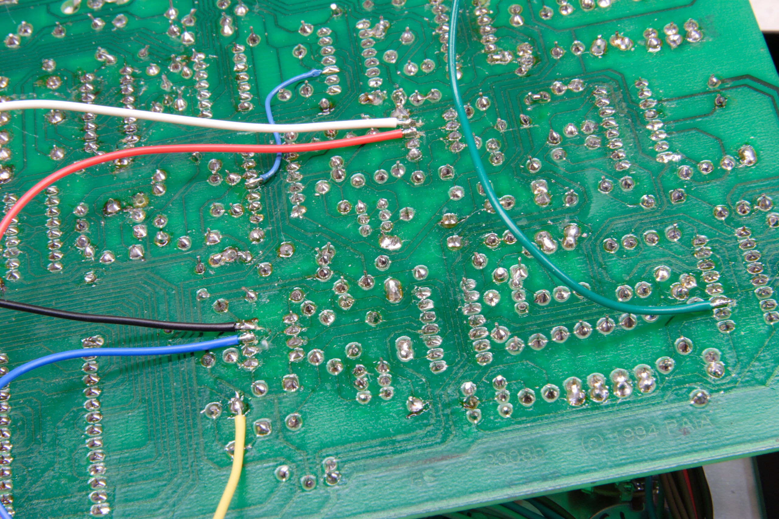
Hmm. Perhaps I should backtrack a bit… After finishing the electrical assembly of my x0xb0x, I found that the LEDs were way too dim. After building the Elenco XP-720K power supply (photo gallery retired), I was able to test out the LEDs with different resistors and find some appropriate ones. It turns out that a 820Ω resistor in conjunction with the LEDs worked out to be exactly what I wanted, bright enough to be seen under a bunch of lighting, but not glaring when in the dark. So, last week I desoldered all 40 resistors which tie to the LEDs, and last night I hooked in the 820Ω resistors, put the x0xb0x back together, cleaned off the flux, then got it all working.

After that installing the new resistors I went through and set everything up with the new Fluke 179 and got it all set up right. The frequency counter in it was especially handy, as it made setting the offset between octives (this synth is 1V/oct). Not long after the synth was all done being tuned, and it sounds great. Then I broke it… More on that later.

Yesterday, as a prerequisite to tuning the synth, I also finished up some work on the Elenco XP-720K (photo gallery retired) by adding heatshrink tubing to the worryingly unprotected IC leads, installing new Bourns 10-turn wirewound pots in place of the original 300° carbon ones, and new knobs from EPD (450-2016). The new knobs were needed as the shafts of the new pots are of a different design, and I also wanted some which allow for a bit finer control. While I like how they look I’m still not sure if they allow for fine enough control. We’ll see…

With the new pots, I am able to easily set the supply voltage to within a few thousandsths of a volt, and with some gentle nudging of the knob I can generally hit the exact voltage I want. Because the pots are wirewound there seems to be a limit to how fine the control I have actually is, but things are still fairly accurate. Adding a second set of wirewound pots (200Ω) as a ‘fine tuning’ control in parallel with the existing ones would help give more control, but it would require drilling more holes and… I don’t know if it is needed. Regardless, I am quite happy with the finished power supply.

So… About how I broke my x0xb0x. Well, to make a long story short, I was playing around with writing my own firmware for it, and after flashing it one of the times, it no longer worked. Details of all what happened can be read here, but the solution ended up being flashing it with alternate firmware, then going back to the original firmware, then wiping the patterns in the EEPROM. I think I had corrupted part of the EEPROM, and as the EEPROM is read as part of setting the tempo as the x0xb0x boots, I think I was making it crash on boot.

Also, I’ve found my firmware with the blinky startup sequence causes my x0xb0x to crash randomly, so that needs work. That’ll come later. Thusly, I’m just using the normal, and originally shipping, v1.04 firmware.

I think I’ll also tag some specific photos of interest here:

· The pile of LED-driving 10KΩ resistors pulled from my x0xb0x.
· Calibrating the x0xb0x’s power supply to 5.333VDC.
· Playing the x0xb0x via MIDI. As a nice surprise, a velocity over ~100 seems to trigger accent.
· The newly heatshrink tube’d IC leads in the Elenco XP-720K.
· Rear view of the Bourns 3504S-1-202 pots in the Elenco XP-720K.
· Two front views of the front of the Elenco XP-720K with the new pots and EPD 450-2016 knobs: 1 · 2

electronicsmaking thingsmoved from livejournal

PAiA FatMan Subharmonic Generator


My first hand-designed and photo resist etched PCB.
(Click for full 600dpi scan…)

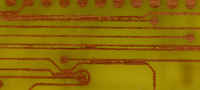
Well, that went well. What you see above is my first hand-etched PCB, and is also a layout I did myself. That right there is the PCB I’m going to add to the PAiA FatMan which I am rebuilding, and provided I interpreted the schematic for the part correctly, that should add two extra octaves of harmony to this synth, giving it some nice, thundering bass.

I should mention that the traces are a shiny silver in person, although I’m not completely sure that I tinned them enough. Also, yes, one of the pads on the left side isn’t quite right. I’m not sure what is with it, as it appears to just be matte in person. It doesn’t matter too much, though, as the reason I made two is to both use up space on the board (it’s 2″ x 4″ and my design was nowhere near that large) and so that if one got screwed up, there would be a second.

So, I guess at this point I’m ready to try etching the double sided board for adding MIDI to my Casio SK-1. I would have done it tonight, but it is getting a bit late to start everything over from scratch…

Anyway, yeah. This makes me happy. Hopefully tomorrow I’ll be getting the order from Mouser which will contain the new resistors for my x0xb0x (photo gallery retired), parts for the FatMan rebuild, and the new pots for the Elenco XP-720K (photo gallery retired).

Mmm… Projects…

UPDATE: Damnit. I don’t know how I didn’t notice it until just now, but there is a 90º bend in one of the traces, when I tried to do everything in… Well… Not 90º joints. Guh. I feel like an idiot, because i know this is one thing that I was trying to avoid… And I somehow missed it in all the times I stared at the printout.

Ah well, It’s only a power line, so it shouldn’t hurt anything… I still feel dumb about it, though.

electronicsmaking thingsmoved from livejournal

DMMs

On the left is my brand new Fluke 179 which just showed up today (thanks, Chad!). In the middle is the Radio Shack DMM I had received from my parents a number of years ago as a gift. My first DMM, if you could say that… On the right is a crappy ‘Cen-Tech’ brand DMM which I purchased from Harbor Freight solely to compare a batch of transistors.

While I didn’t expect the Harbor Freight meter to be even remotely accurate (after all, it cost $3 or $4), when hooking all three DMMs to the same power supply, it is surprisingly close to the Fluke. Wow.

This isn’t to say the Fluke wasn’t worth it, as it is amazingly responsive, easy to use, and does all sorts of things well… And being properly calibrated and all, I can trust its results. I’m just amazed that the general piece-of-crap from HF was more accurate than the one I’ve been using for years. I guess I should have replaced it sooner.

acquired thingselectronicsmoved from livejournal

First Board Layout

Hey, look. It’s the first PCB layout I’ve ever done… Seems to be okay, too. The autorouter didn’t do as good of a job as it could have, but that’s okay. This isn’t what I’ll actually be producing the board from, I just wanted to be sure I had a good understanding of how to do it.

Oh, and that board up above there will be for this subharmonic generator for the PAiA FatMan, the two octive version. It’ll be connected to the board and front panel via flying wires. (Yes, there will be photos once I actually do it… The parts are on order.)

And yes, that should say “Subharmonic Generator” in there. I’ll fix it later.

electronicsmaking thingsmoved from livejournal

PAiA FatMan Plus Panel Idea

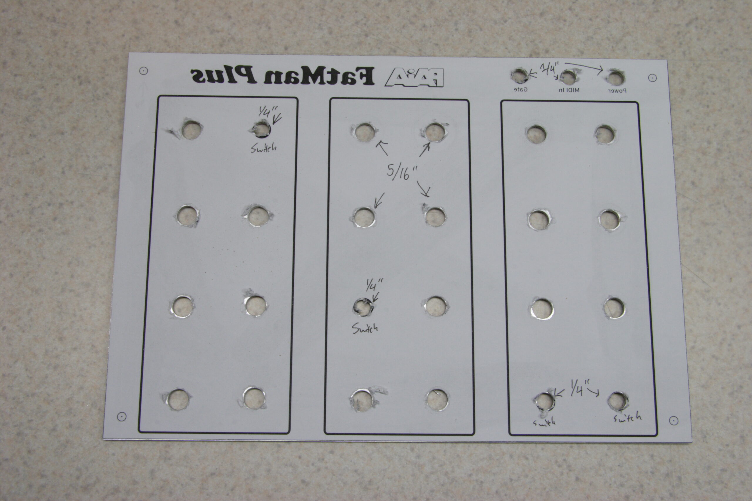
Up above there is the rough idea I just threw together for the front panel of the PAiA FatMan which I’m rebuilding. I am going to be putting it in a new enclosure and adding some extra stuff to it, so I need to design a new panel.

I’m curious if those of you who are familiar with using synths what you think of this… I tried to somewhat follow the original FatMan desktop enclosure layout, adding the mods (subharmonic generator and VCO hard sync) where appropriate.

No, things aren’t lined up yet, labels aren’t in there appropriate places, and there are no knob position indicators… I’m just trying to get some layout ideas. Also, the three vertical columns of controls will be sized the same and properly centered. Also, the groupings will be labeled similarly to how the VCF one is. Oh, and the whole thing will likely be in white lines and text on black, similar to the x0xb0x. It’s just easier to start designing this way.

So, what do you think? What would you change?

Thanks!

electronicsmaking thingsmoved from livejournalmusic