HMLiberator Works! (Mostly…)
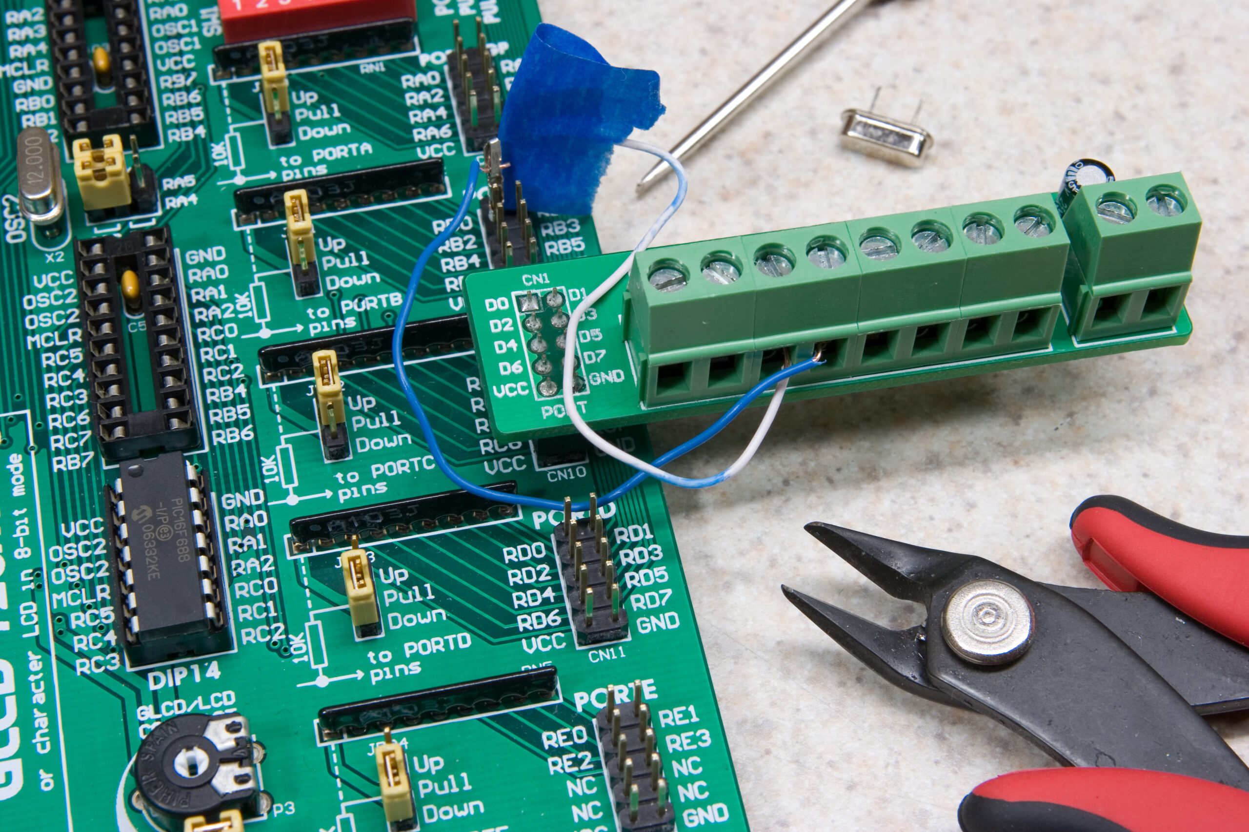
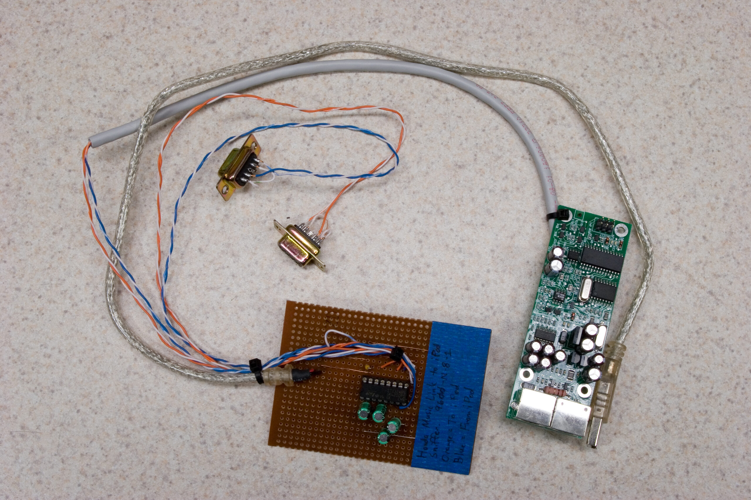
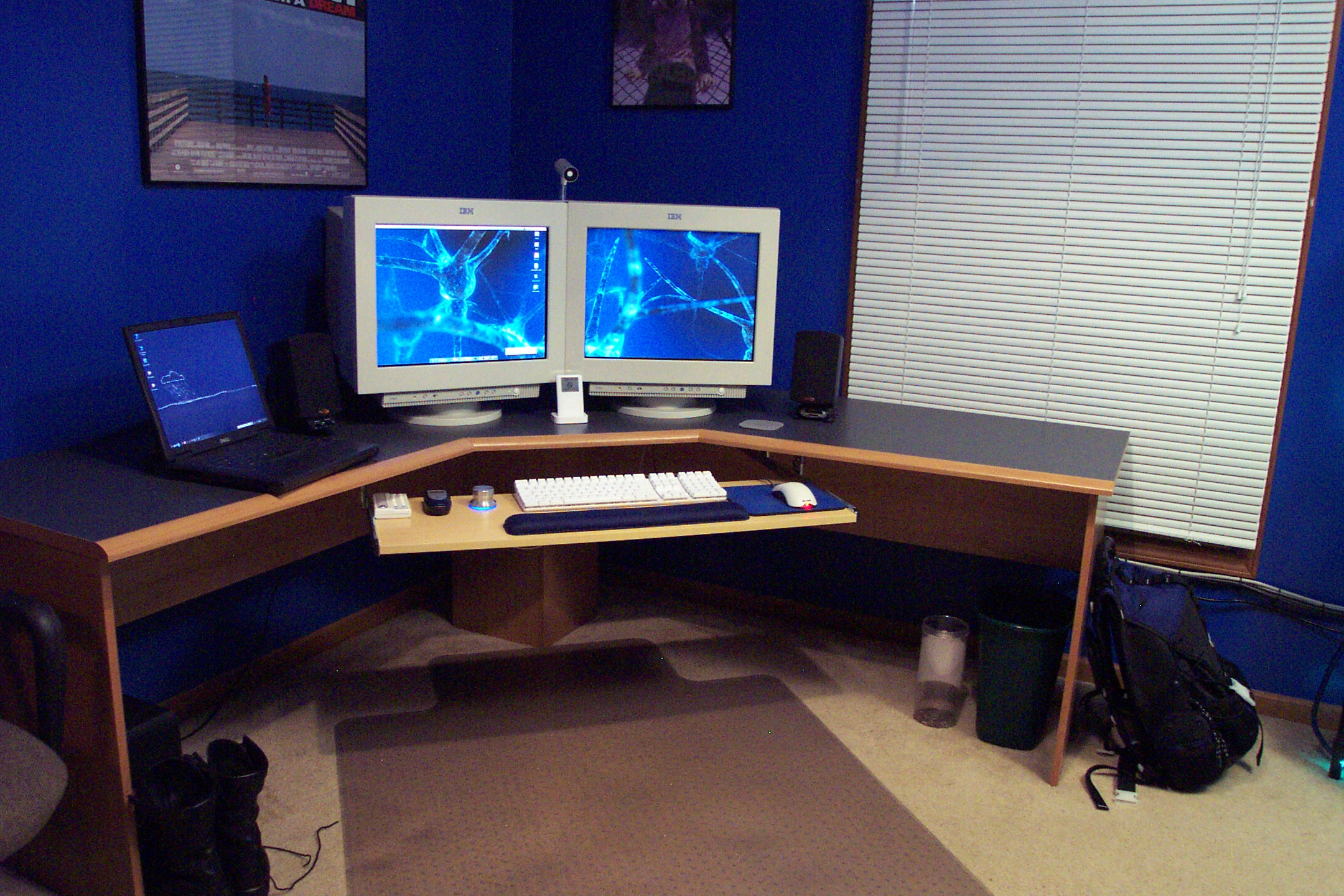
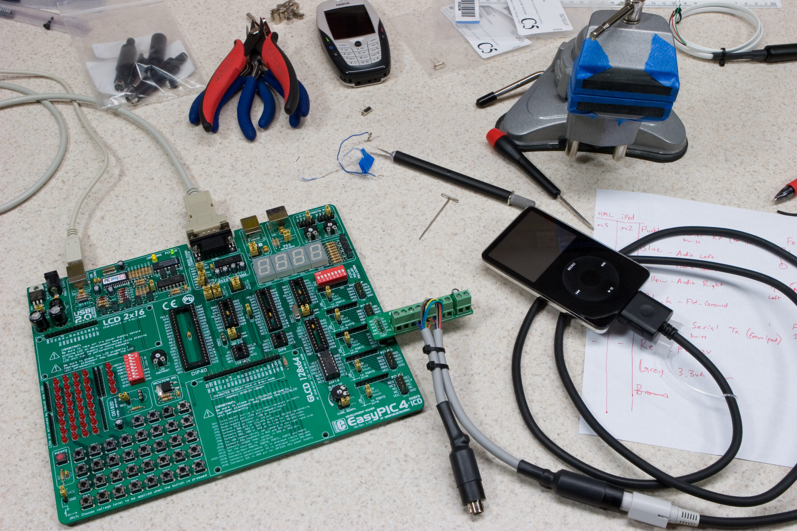 The EasyPIC4, iPod, Honda Music Link iPod Cable, and serial breakout cable,
all connected and ready for testing.
(Click for more photos of HMLiberator development.)
Well, it pretty much works. By “pretty much” I mean that the Honda Music Link talks to it, the HMLiberator replies, and things seem okay. I’m stuck at one point, where the Honda Music Link (HML) asks the iPod (really, the HMLiberator) for information about the two playlists it reports containing, and the HML doesn’t seem to like the answer. I think I screwed up at least one of the packets, so I’ll look into that tomorrow and do a bit more testing. The good news is that it all generally works and right now the problem is software related.
I’ll try and fix it tomorrow.
I uploaded a few more photos, which I’ll just mention here:
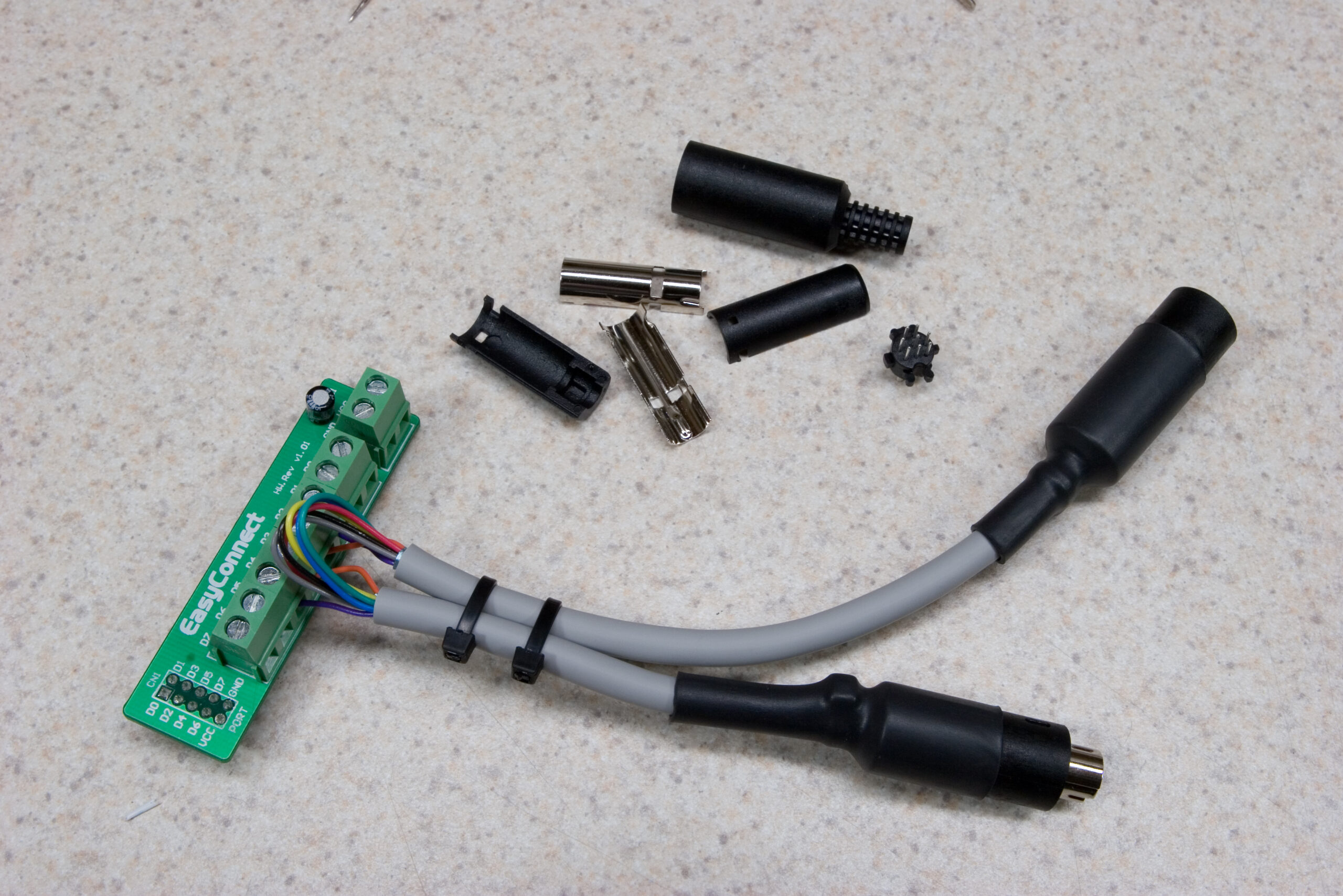
· Inside of one of the MiniDIN 8 connectors, with fingerprints for scale.
· Completed straight-through cable, to be split open for serial data testing.
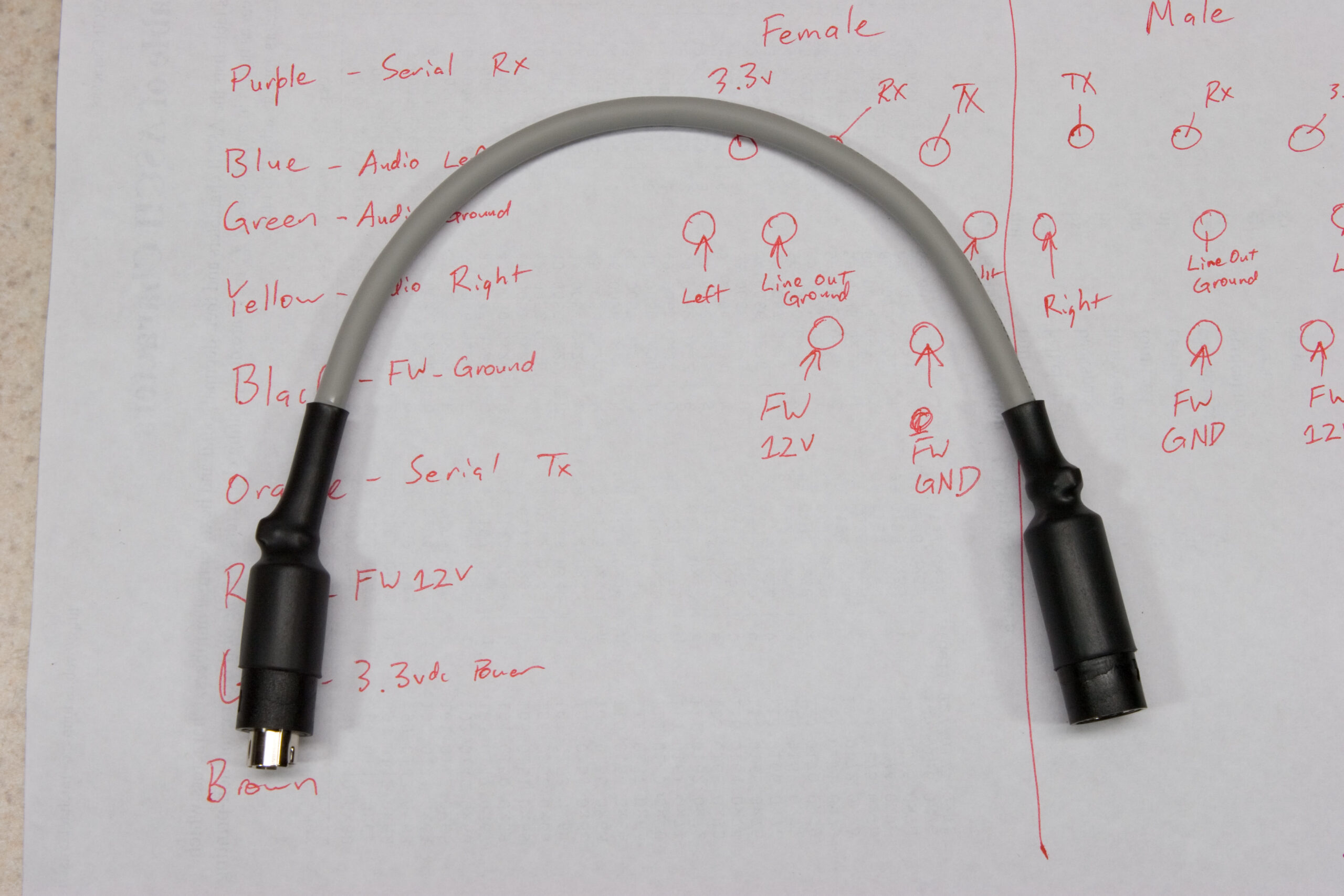
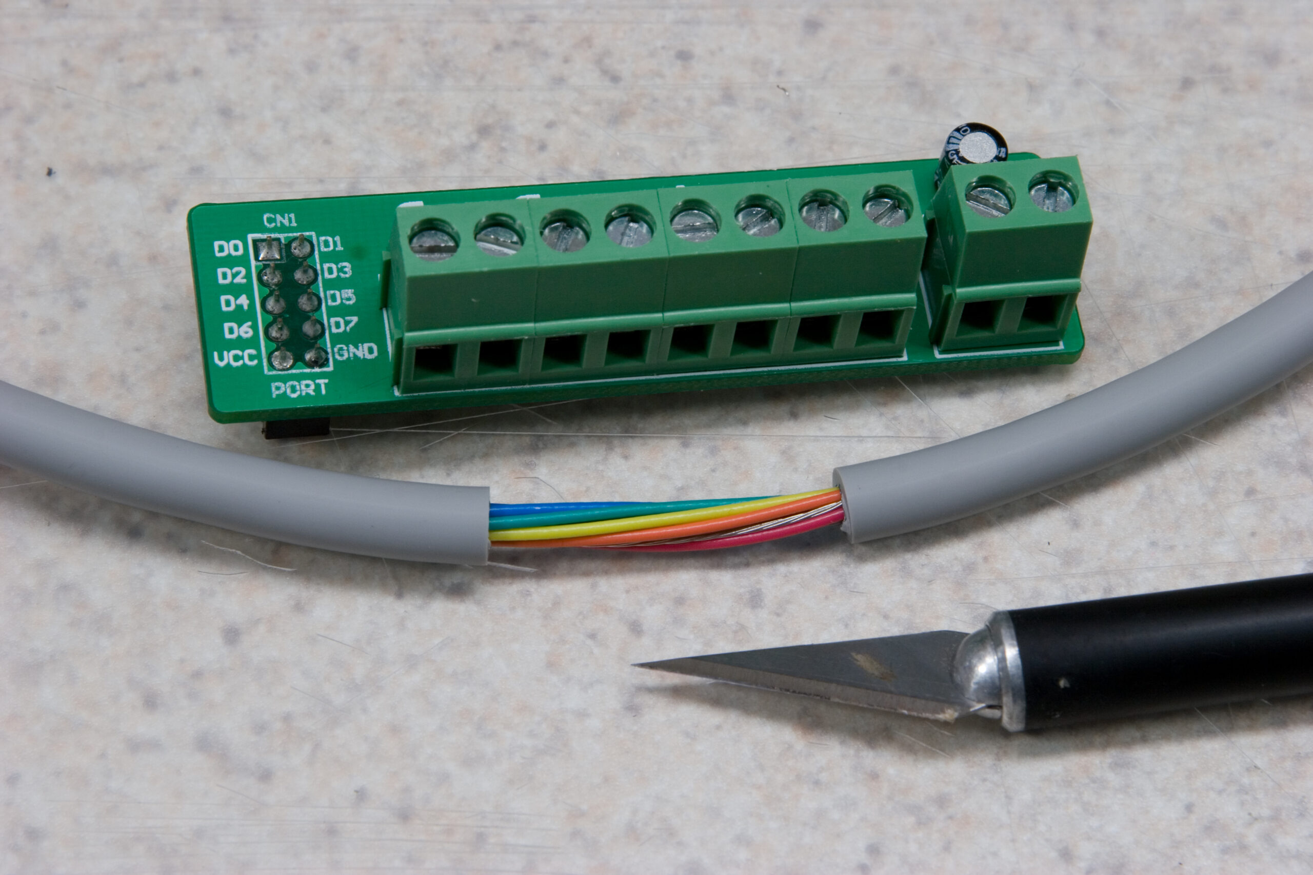
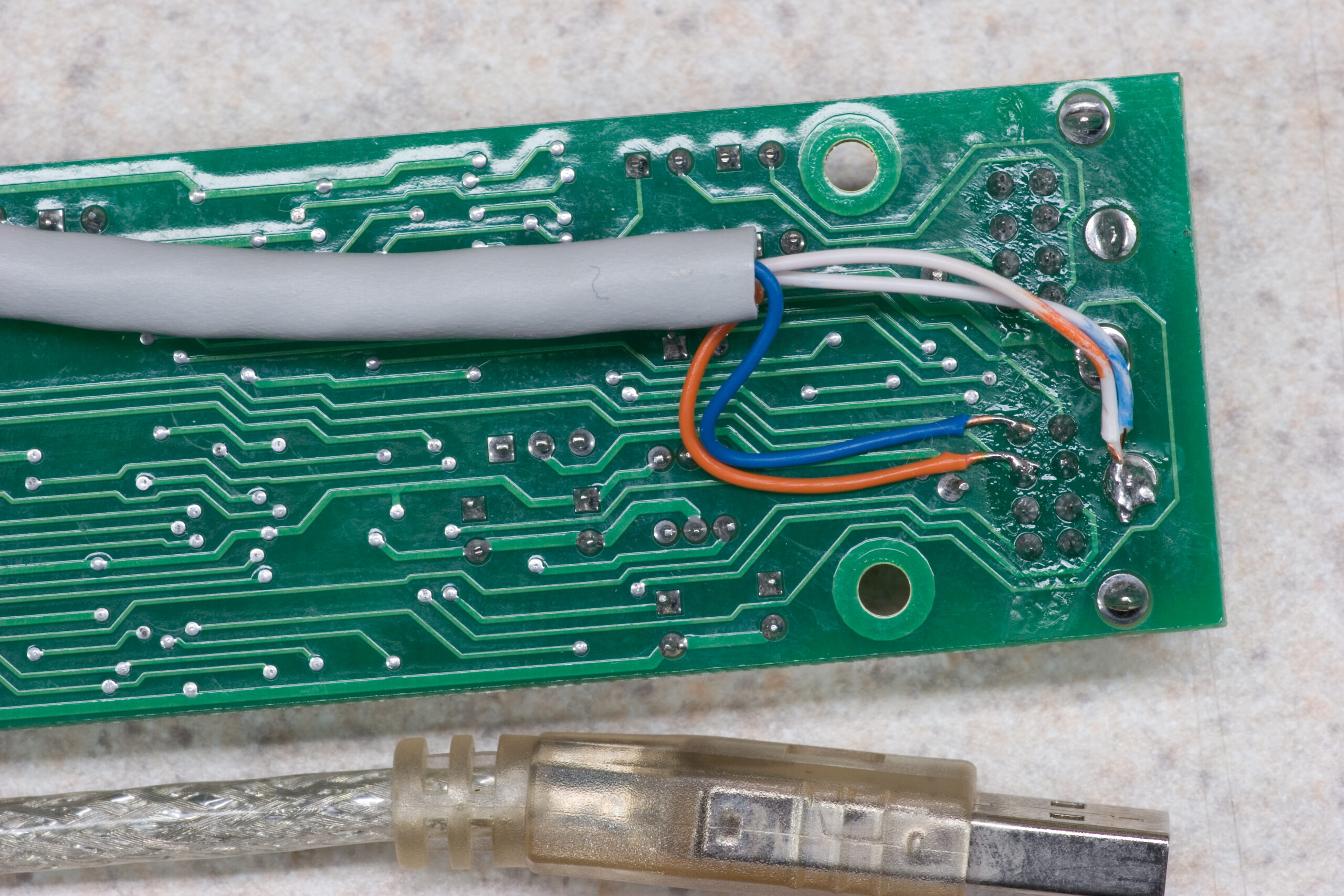
· Cut open data cable, ready to tap into the serial TX and RX lines.
· Completed serial RX/TX tap, except I forgot to connect the ground line. Whoops! It works when grounded through the sniffer, though.
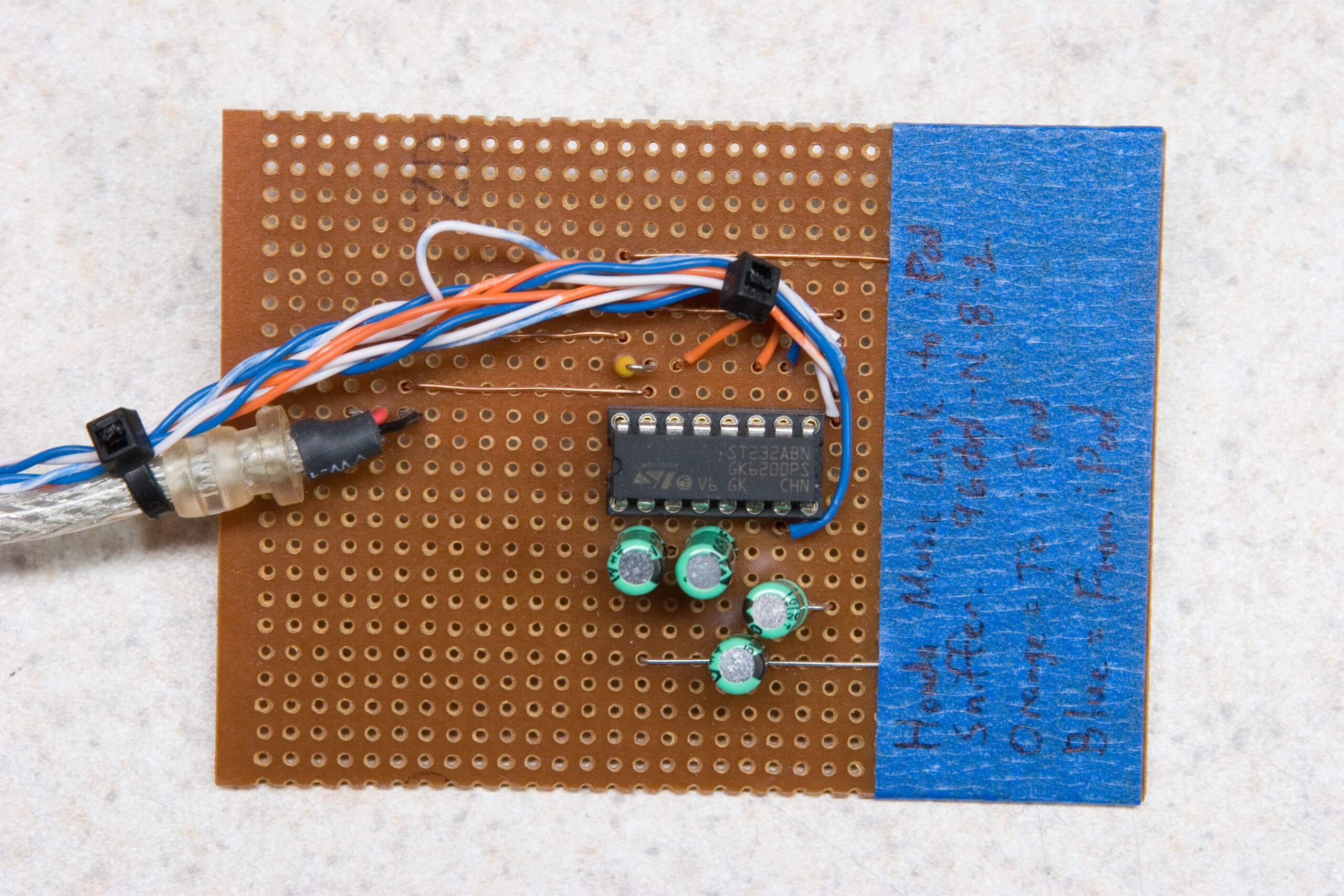
· My Honda Music Link sniffer. A level shifter, strip board, and some DB9 connectors.
· Detail of the top of the HML sniffer.
· Showing where the HML sniffer taps into the serial TX and RX lines which the HML uses to talk to an iPod.
This part is probably even less interesting to most people, so I’ll hide it behind a cut:
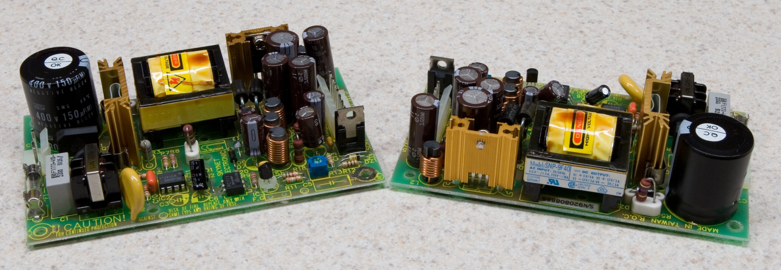
 Skynet SNP-9F40
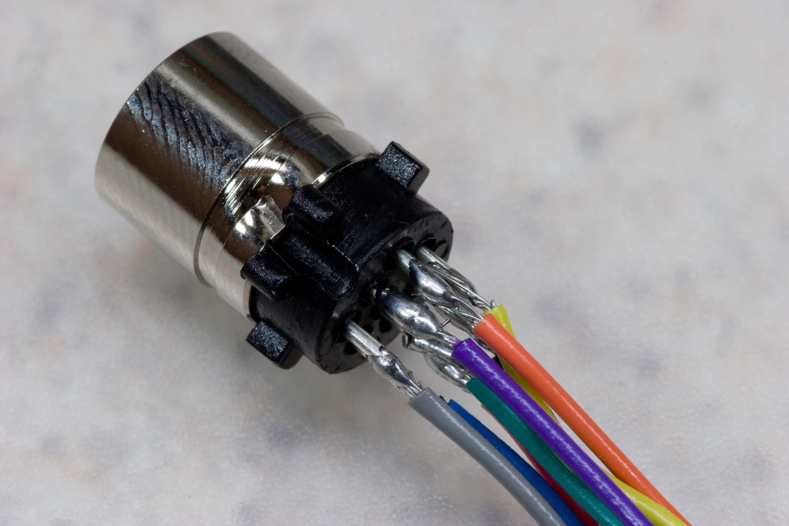