nuxx.net
Making, baking, and (un-)breaking things in Southeast Michigan.

Category making things

NES 72-Pin Edge Connector Replacement

NES Internal Screw Removal

NES Internal Screw Removal

After acquiring some replacement NES 72-pin edge connectors to fix NES’ for both replika and I, I decided to take step-by-step photos of the replacement and write up a tutorial on it. So, I give you my NES 72-Pin Edge Connector Replacement Tutorial.

This is actually really easy to do, fixes the blinking-gray-screen problem which plagues almost every front-load NES (you know, the problem which were supposedly resolved by blowing on the connector in the cartridges), and can be done with just a screwdriver and replacement connector. There is no soldering or electrical repair skill needed for this.

Also, please Digg this story.

electronicsgamesmaking thingsmoved from livejournal

Atari 1050 is looking up!

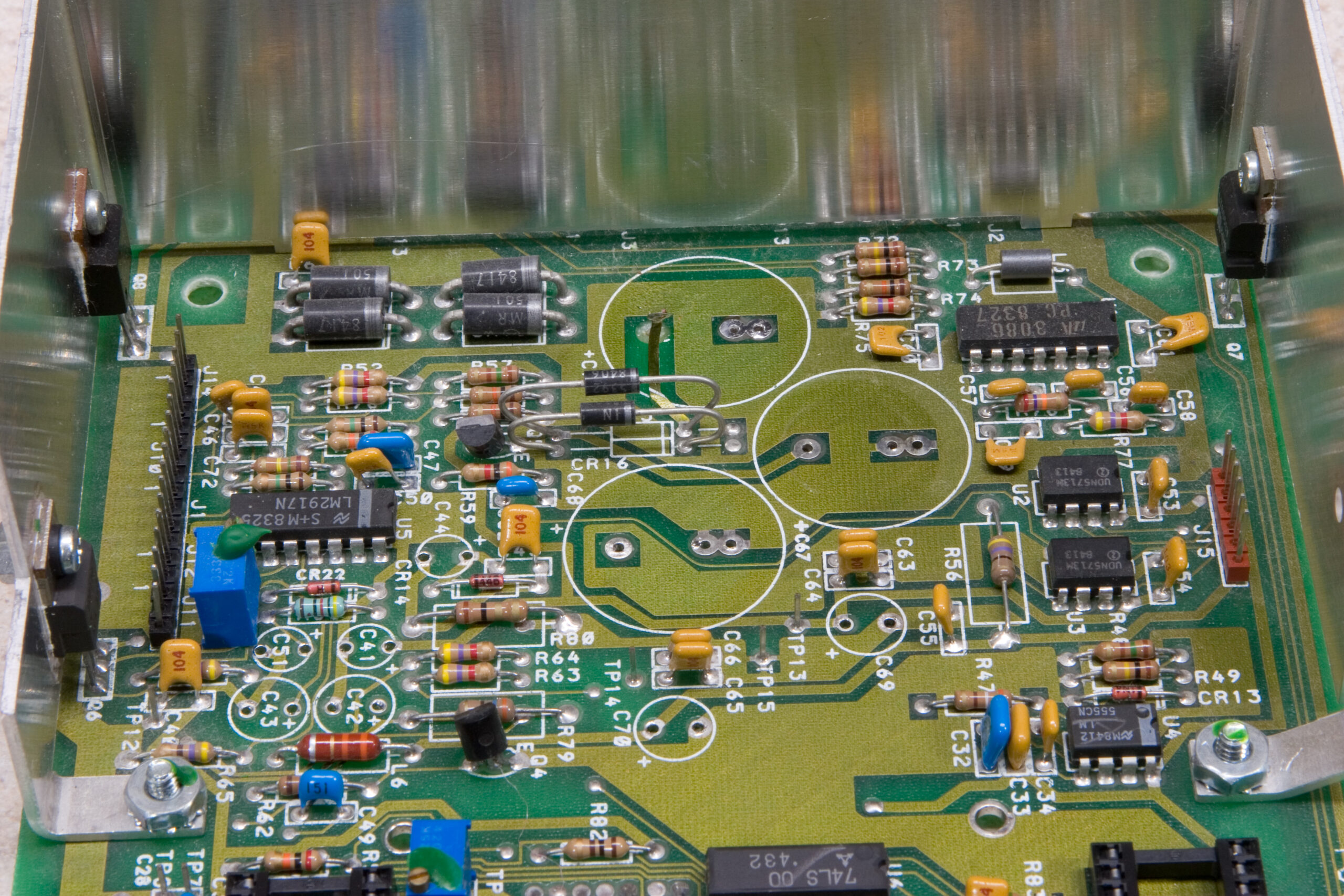
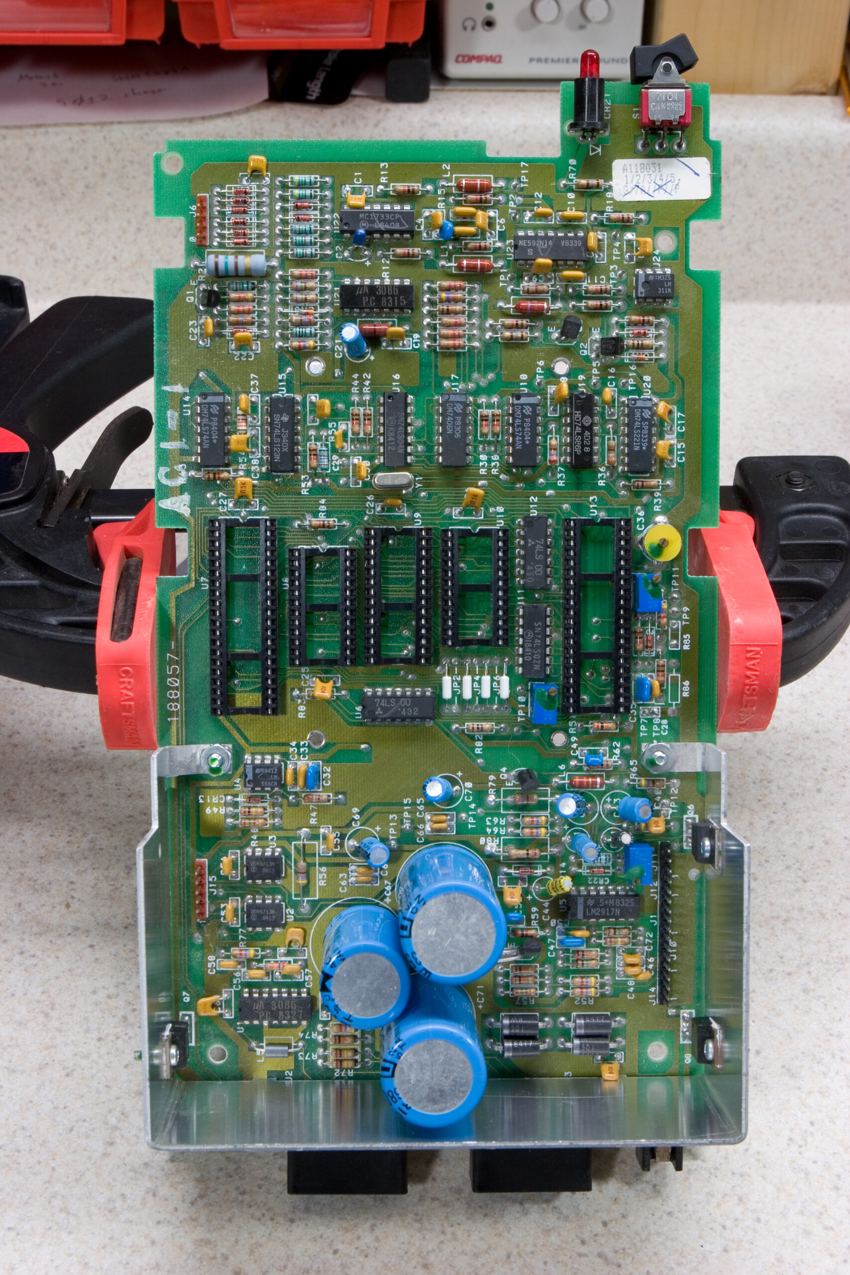
Atari 1050 drive PCB with most of the electrolytic caps removed.

Atari 1050 drive PCB with most of the electrolytic caps removed.

Well, it appears that I’ve got the problem with the Atari 1050 sorted out. It seems that some of the 47μF caps (C42, C43, C69, C70) were bad, causing the shorts. I’ve also removed all of the other electrolytic caps and will be ordering replacements from Mouser tomorrow. (The board had looked like this before.)

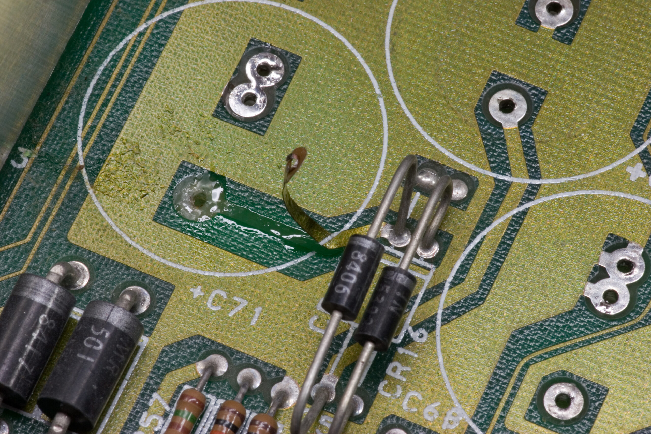
I did make one pretty substantial mistake and inadvertently lift a trace on the top of the board when removing one larger caps. The hole really didn’t seem through-plated and the leg of the capacitor didn’t let go from it, and I peeled it right back. Thankfully it should be very easy to jump around with a 2″ piece of wire, so when I put it back in place I’ll do that.

Hopefully by the end of the week I’ll be able to properly image old 800XL floppies. Yay!

electronicsmaking thingsmoved from livejournal

Atari 800XL Composite Video Cable

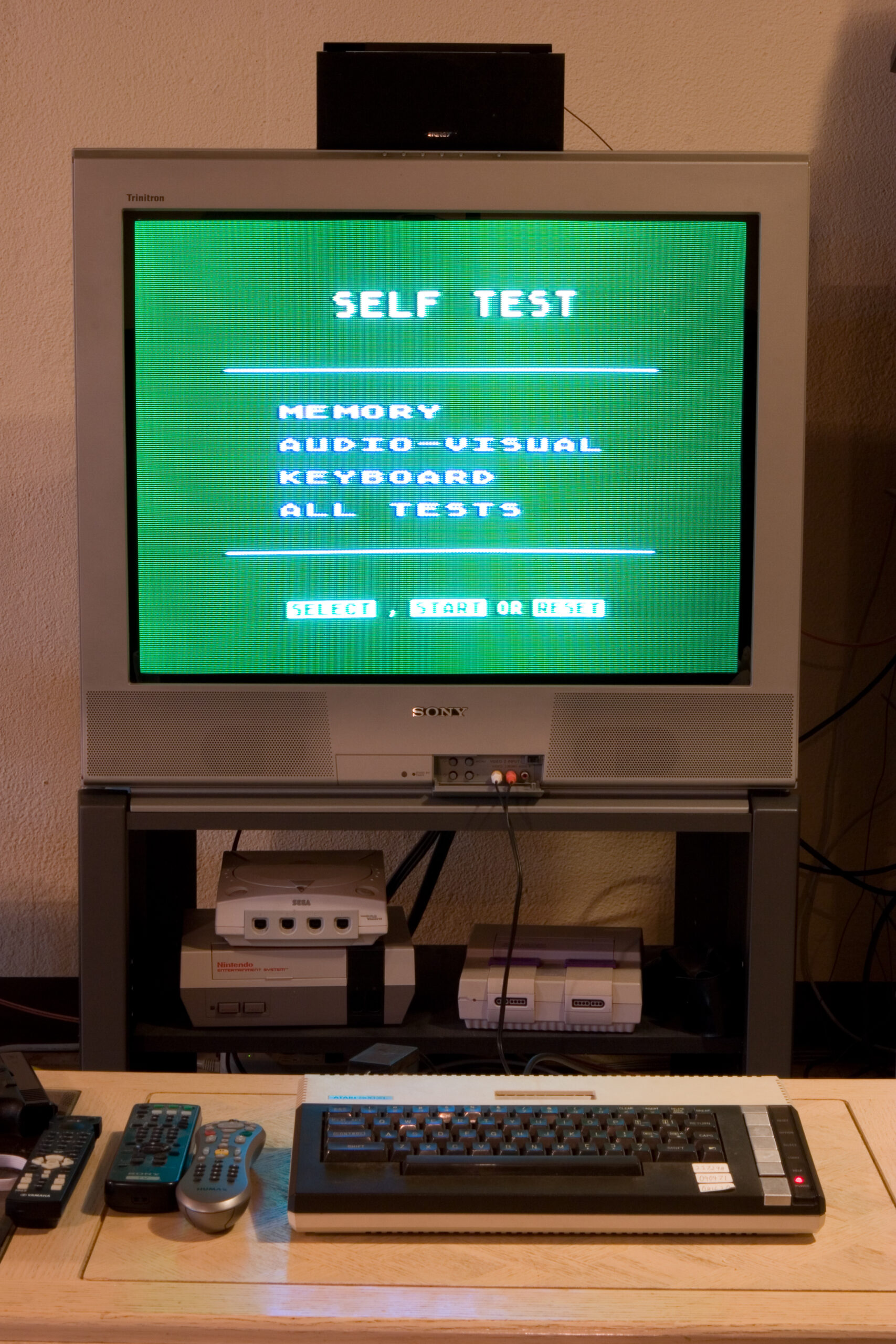
Atari 800XL and TV

Atari 800XL and my TV

Thanks to this page about the Atari 800XL’s monitor connection output I was able to cobble together a composite video output cable for my parents old Atari 800XL. Thankfully the monitor connection is a standard DIN5 connector, so it was made by sacrificing a spare MIDI cable and an old red / white RCA cable pair.

After the SIO2PC adapter arrives and I’m able to either fix my Atari 1050 floppy drive or borrow one from someone I’ll begin imaging the whole box of floppies leftover from my youth. This will be done using Ape and ProSystem to copy all the old disks to images so they can be archived. Then they can either be run under emulation, or directly on the 800XL with the PC pretending to be the floppy drive (via the SIO2PC).

I should probably also consider doing something with the tape drive as well. Maybe pulling data / games off of that or something… Hmm…

electronicsmaking thingsmoved from livejournal

9090 Front Panel Proposal


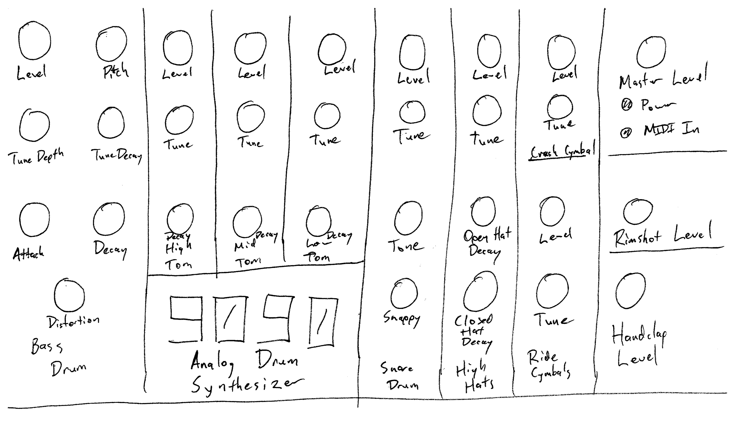
My first layout idea for the front panel of a desktop 9090, scrawled on a piece of paper.
(Click for higher res image…)

So, that 9090 that I’ve been working on? I’m really needing a project to work on again, so I’m going to keep working on it. It needs two caps installed on the board, an enclosure built, and final assembly, wiring, and testing.

This afternoon while on a conference call I figured out the number of pots I’d need and scrawled an initial layout on a sheet of paper. That there is what I came up with.

I’m curious what those of you who have used similar drum synths (or have an opinion on physical UI design) might think.

I may switch the Rimshot Level and Handclap Level (lower right corner-ish bits) around, and the LEDs and Master Level knob (upper right corner) might need some adjusting. Maybe move the Ride Cymbal set above the Crash Cymbal set.

So uhm… yeah. Any ideas?

electronicsmaking thingsmoved from livejournal

Lightsticks In The Toilet


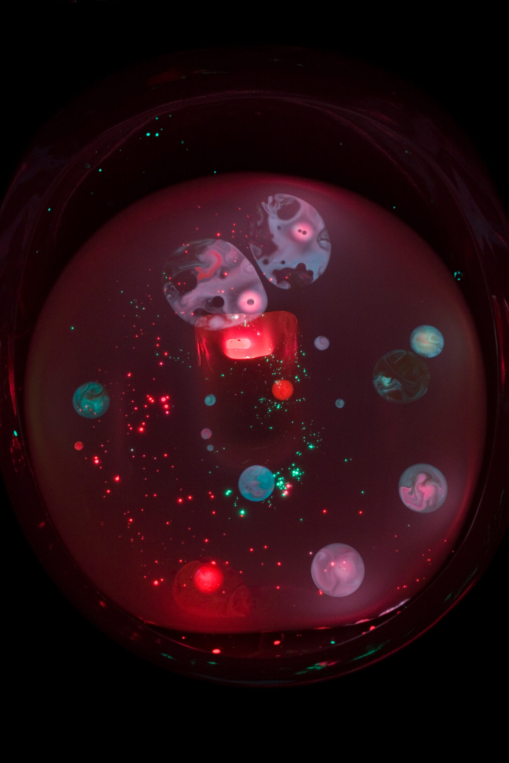
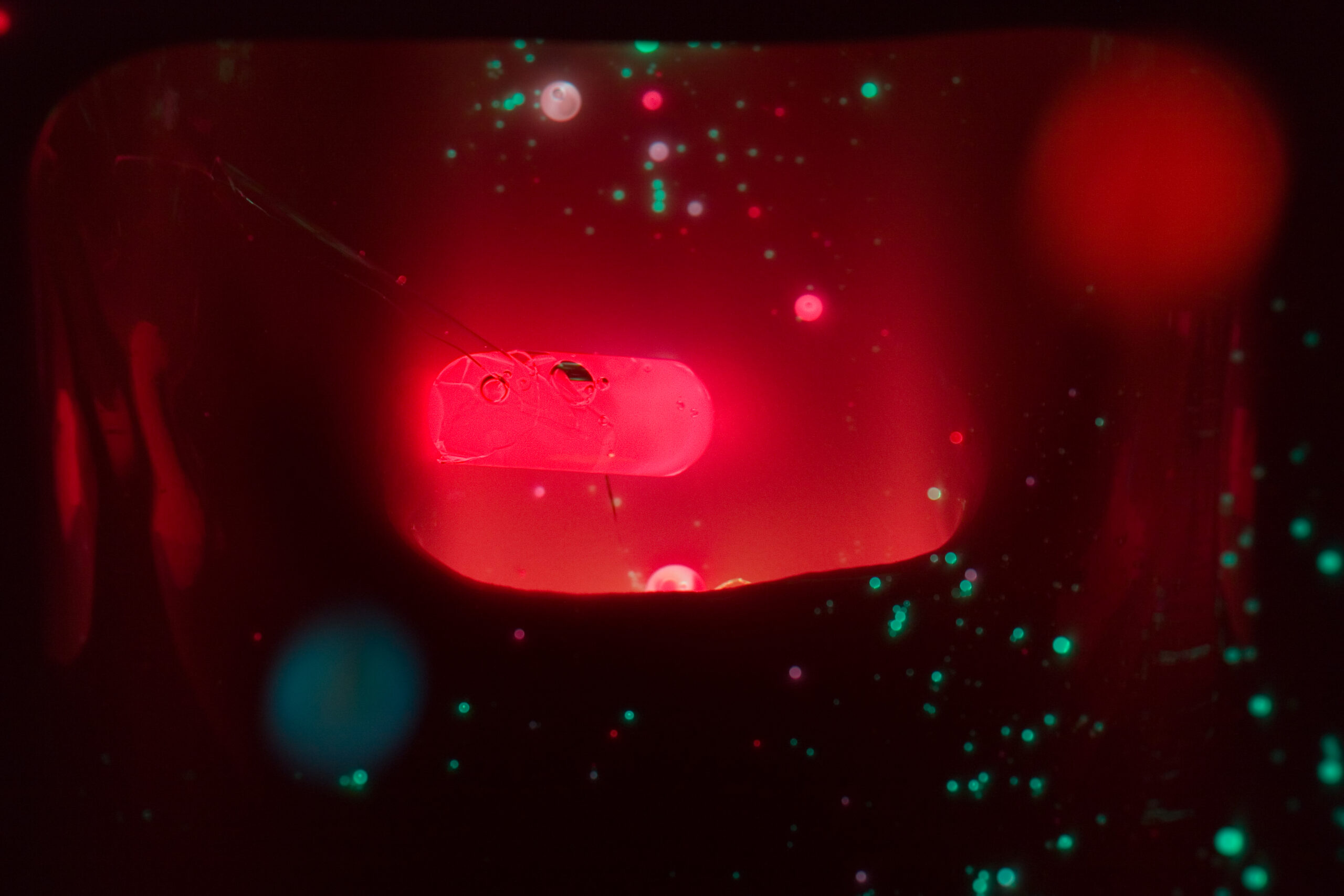
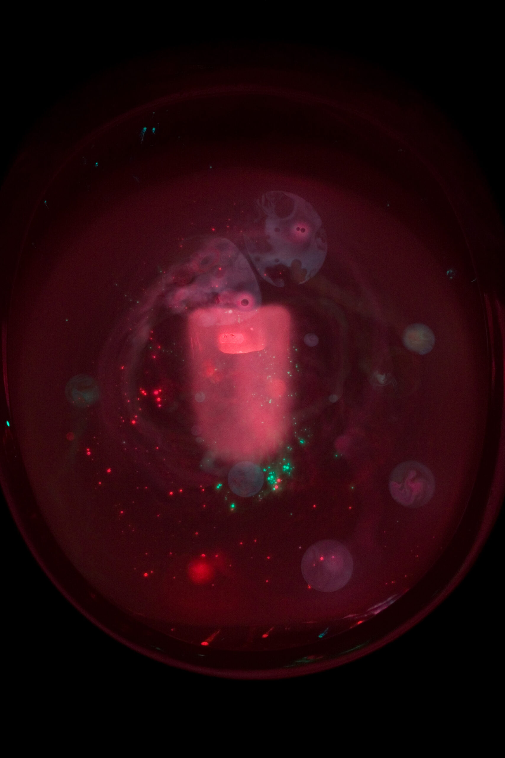
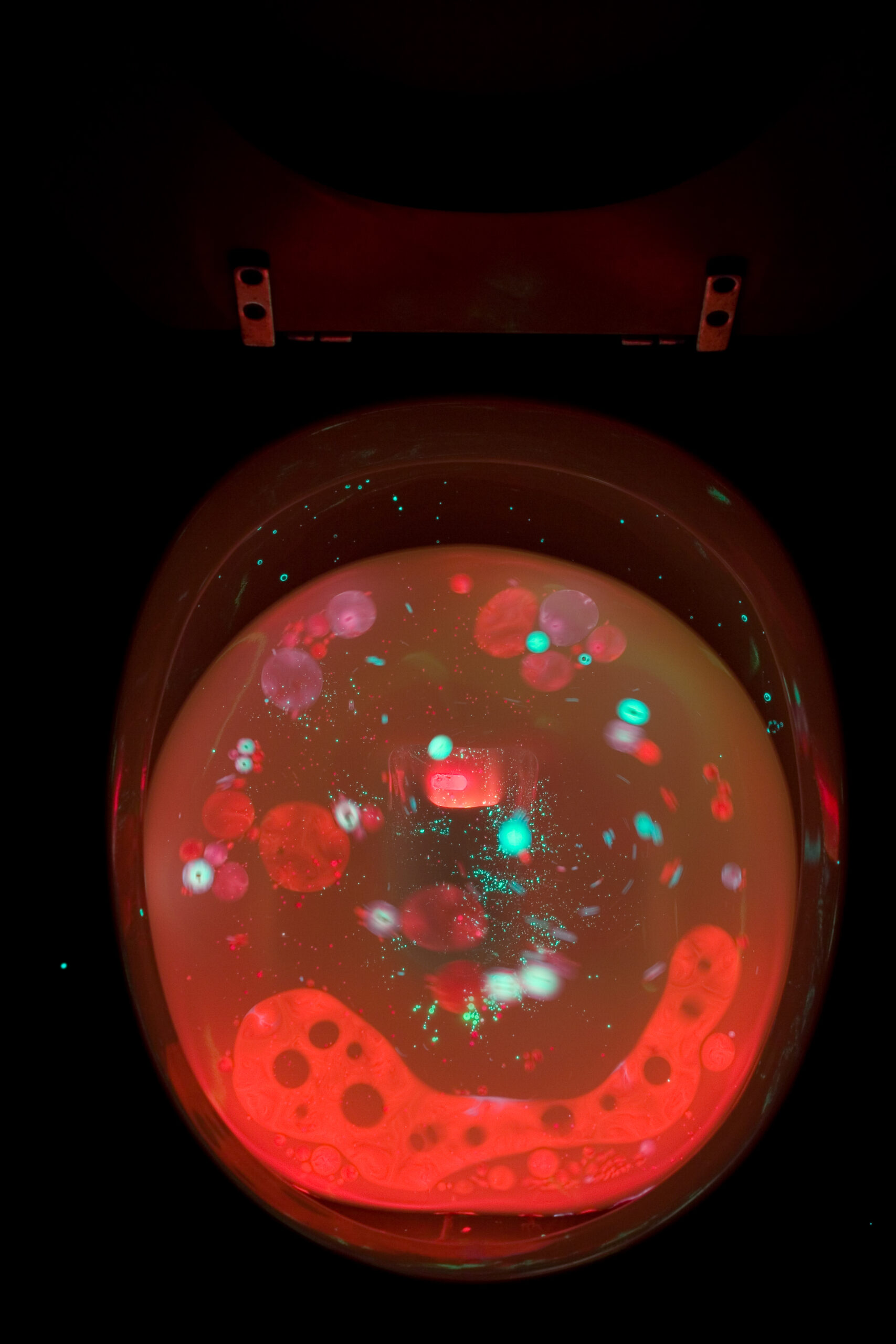
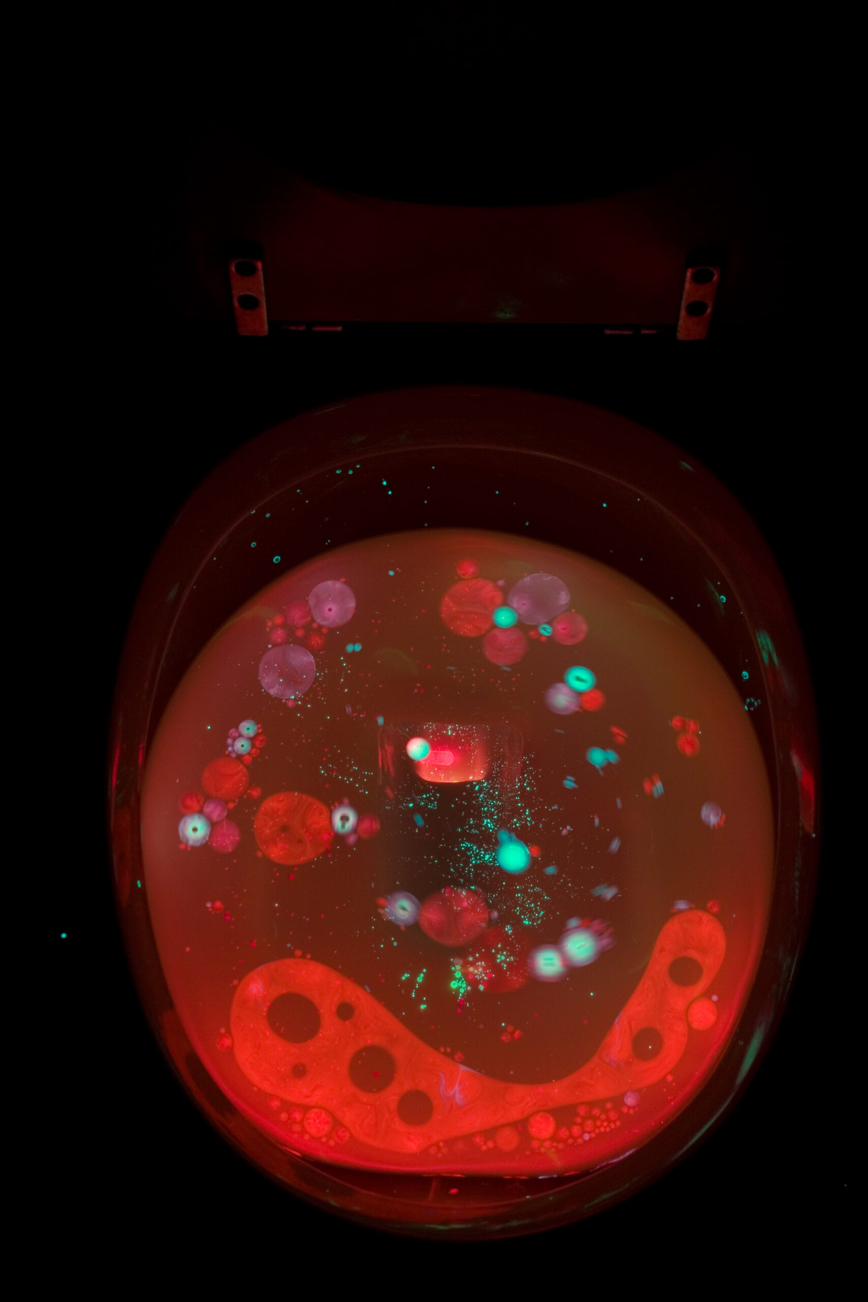
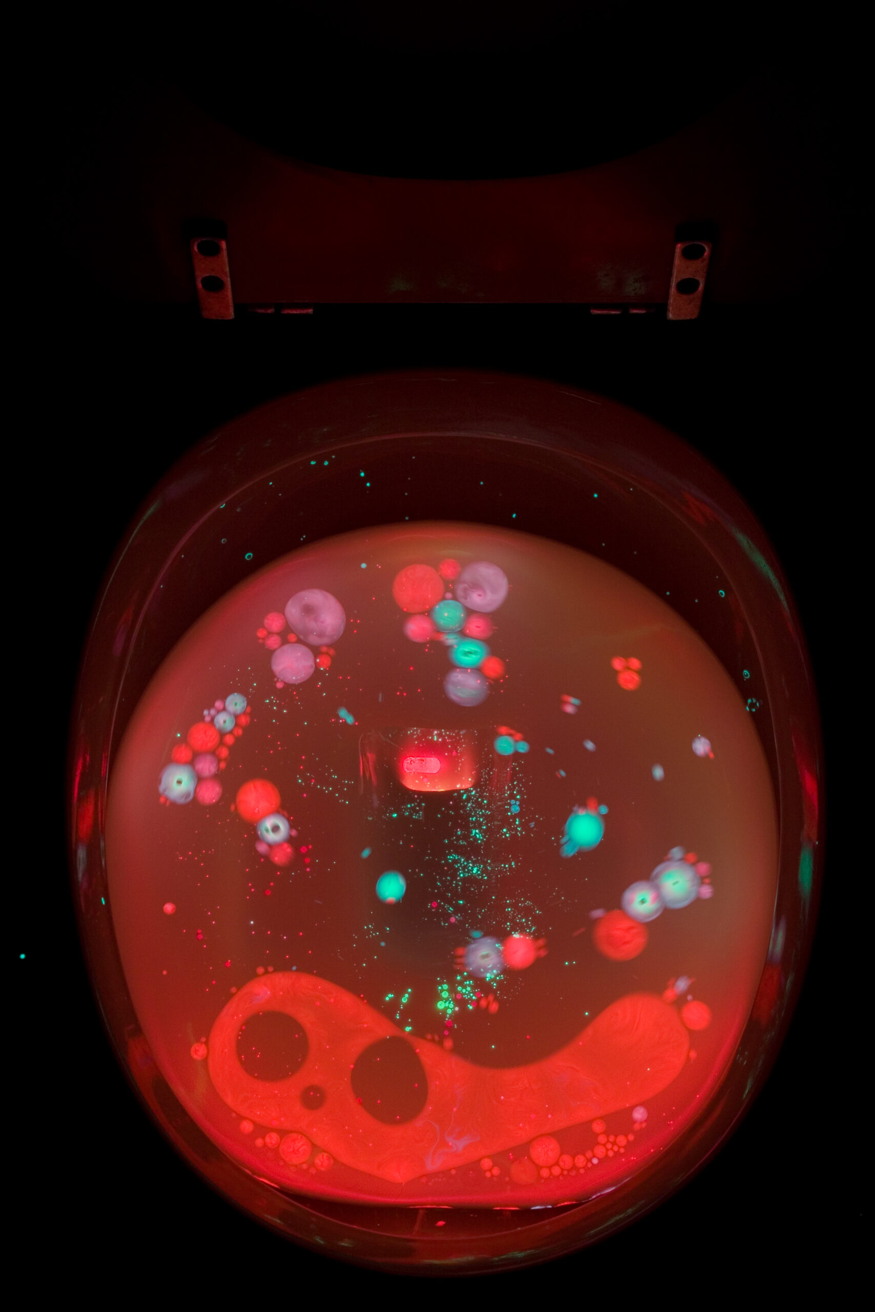
Toilet after pouring in the contents of green and red cyalume lightsticks.
(Click for more photos of playing with Lightsticks In The Toilet (photo gallery retired)…)

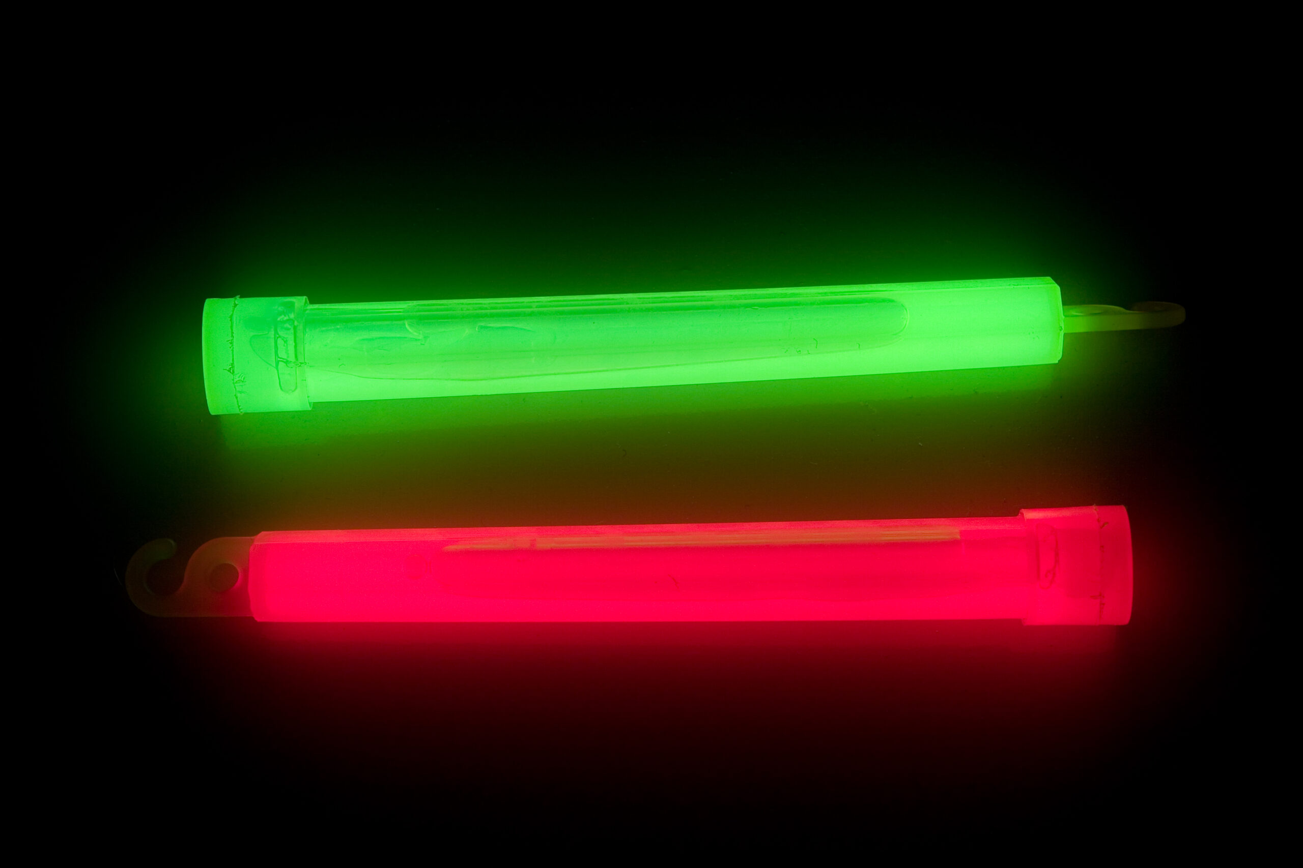
Tonight while going through a few old boxes in the basement I came across red and green lightsticks, still in the wrappers. So, I opened them and activated them. After playing around with them for a little while I decided to do something I played with when I was much younger, except this time I decided to take some pictures of it.

What did I do? I cut open the light sticks and poured them in the toilet, watching the slowly changing, swirling psychedelic glow emanating from my toilet. Unfortunately these toilets aren’t that great for it, as most of the oily phenyl oxalate ester and H2O2 ran down into the bottom of the toilet and out of view. Still, there were some interesting things to see.

  
(Click to view each image at a larger size…)

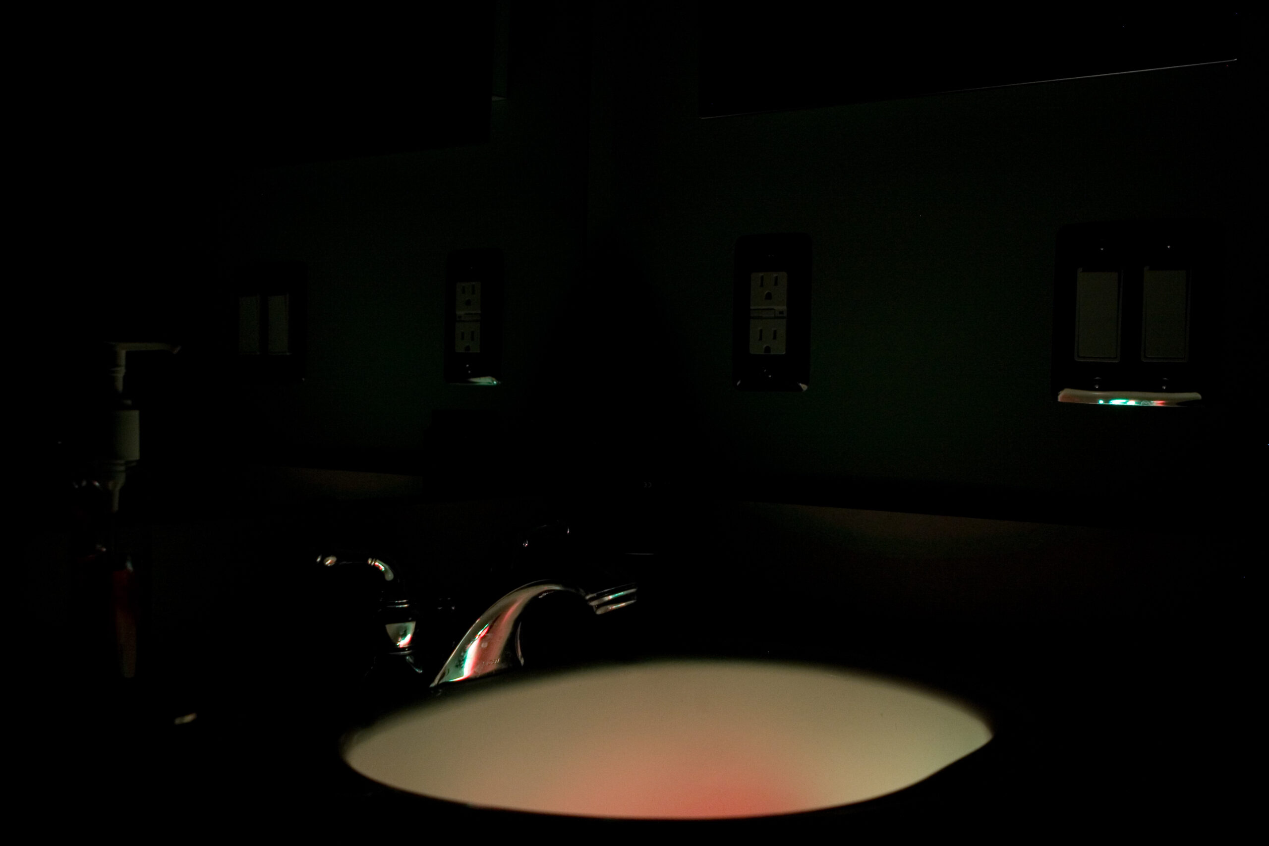
More photos of this all are available here in the Lightsticks In The Toilet (photo gallery retired) album. Some of the better photos are:

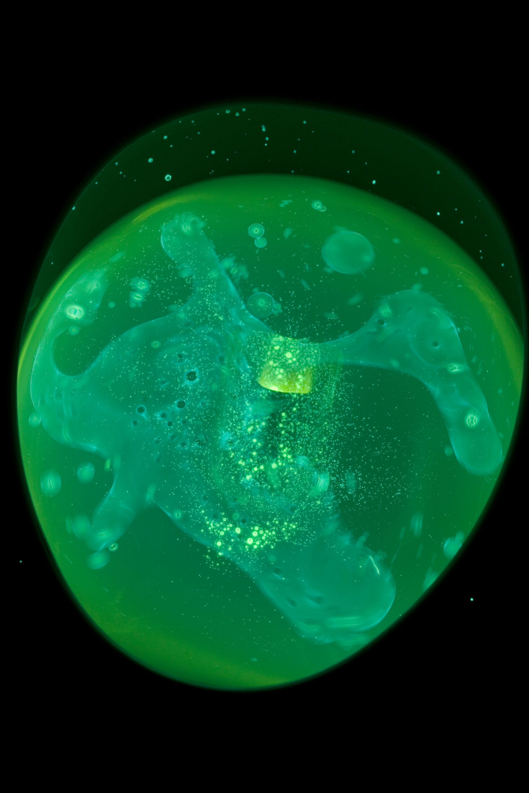
· Toilet water with just the green cyalume lightstick compound in it.
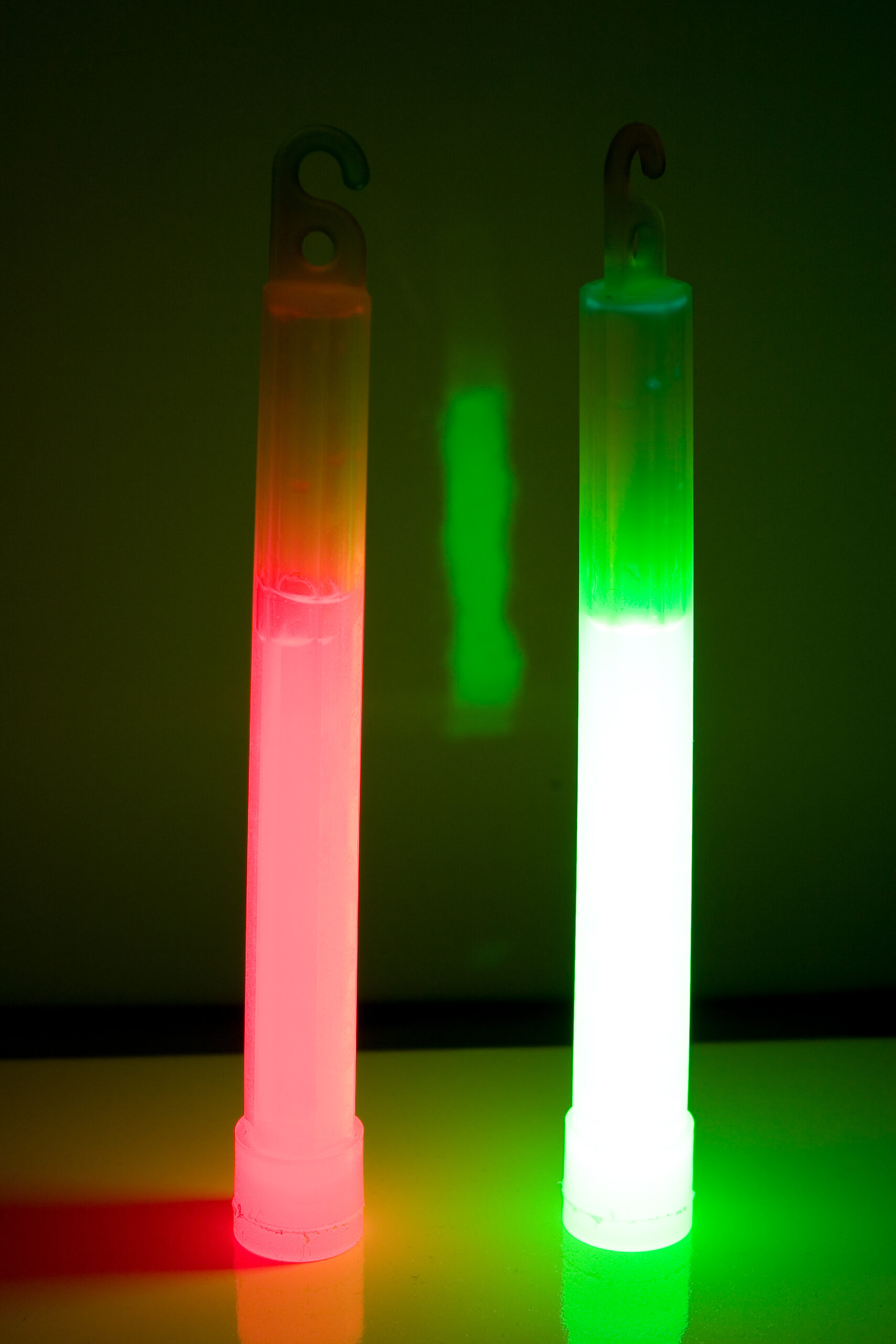
· Red and green cyalume lightsticks setting on the toilet lid.
· Closer image of the toilet water containing cyalume lightstick compound.
· Lightstick compound swirling down the toilet as it is flushed.
· Photo 1 of red and green cyalume lightstick compound in toilet.
· Photo 2 of red and green cyalume lightstick compound in toilet.
· Photo 3 of red and green cyalume lightstick compound in toilet.
· Photo 4 of red and green cyalume lightstick compound in toilet.
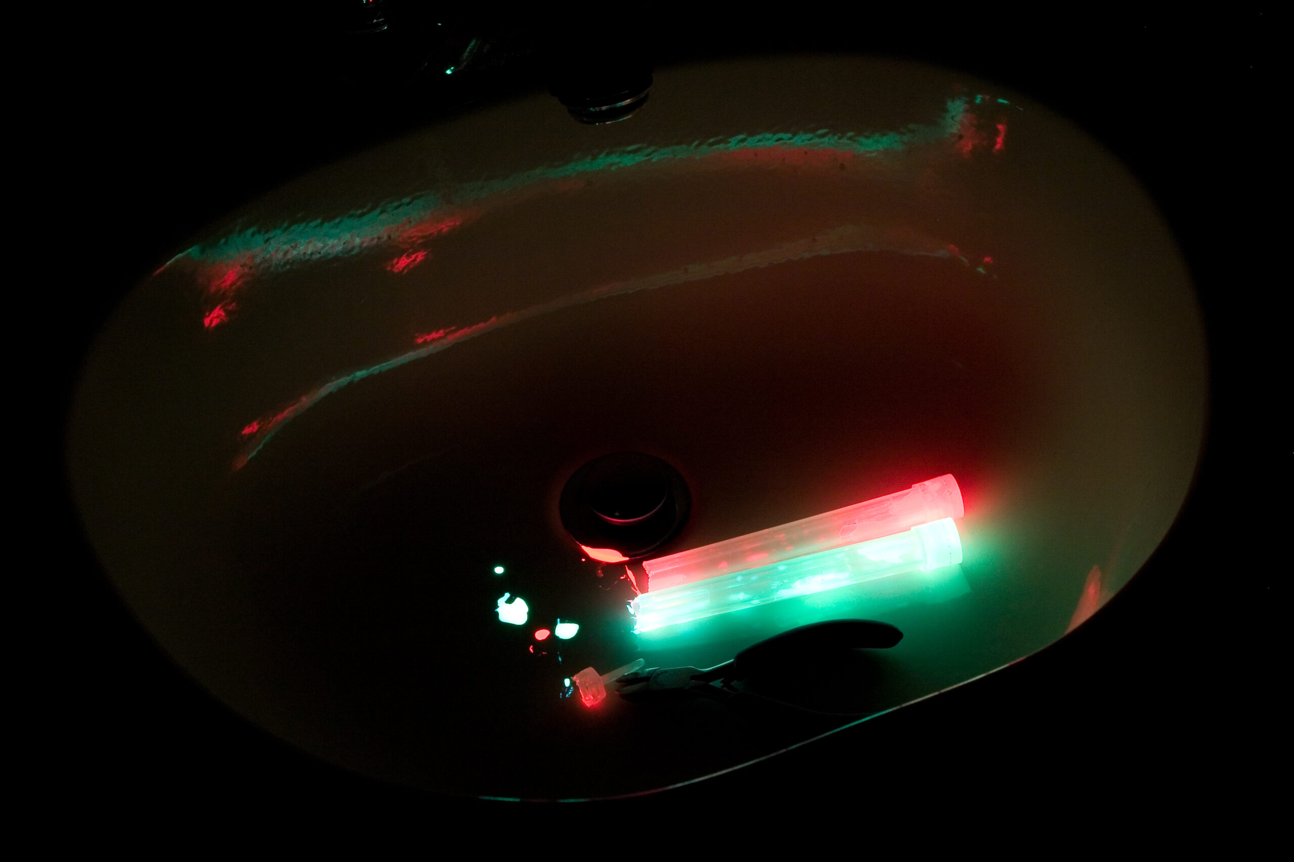
· Glowing sink containing the remains of the cut open lightsticks.
· Lightsick remnants and cuts in the sink where I set them so they wouldn’t make a mess.

around the housemaking thingsmoved from livejournal

9090 Update


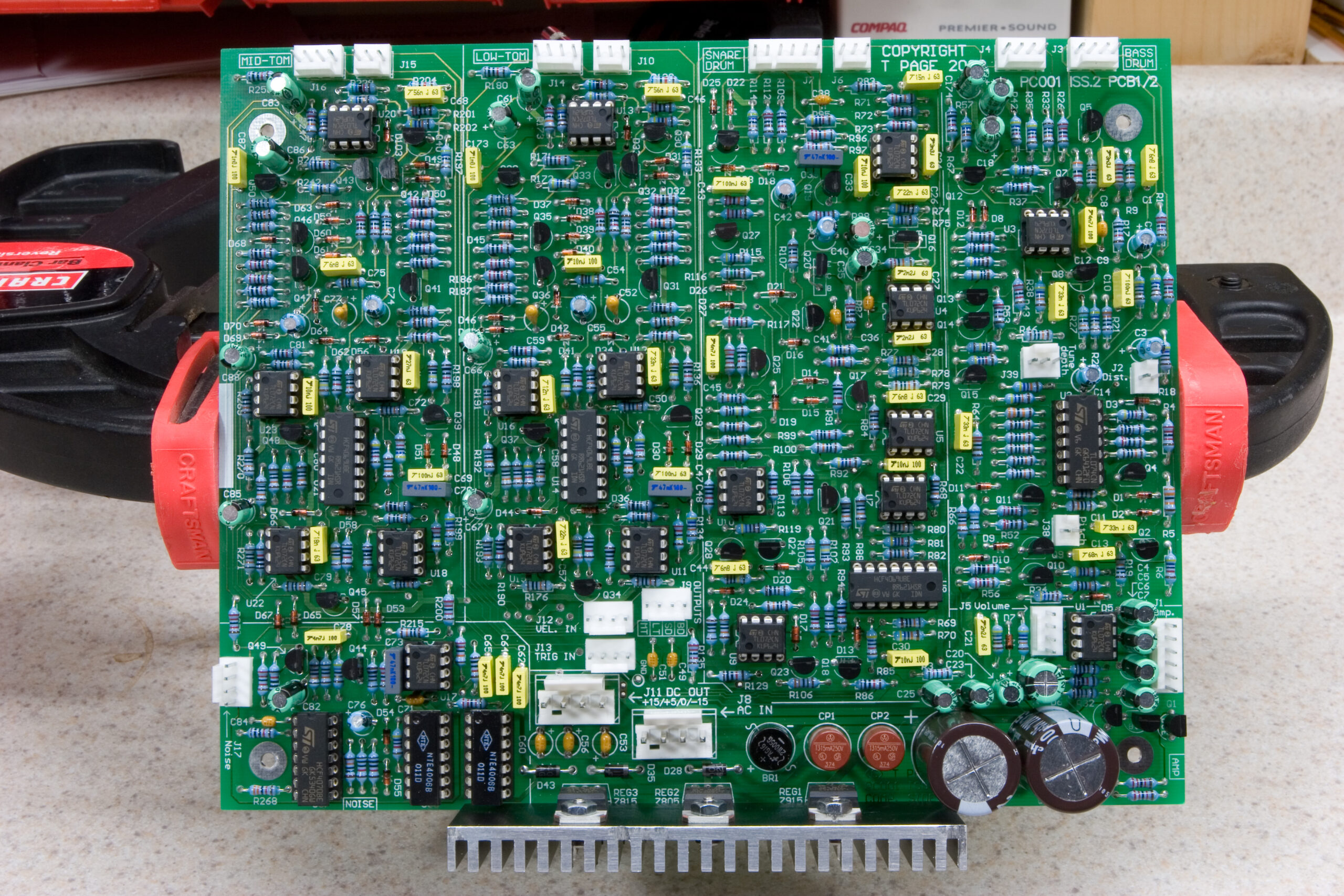
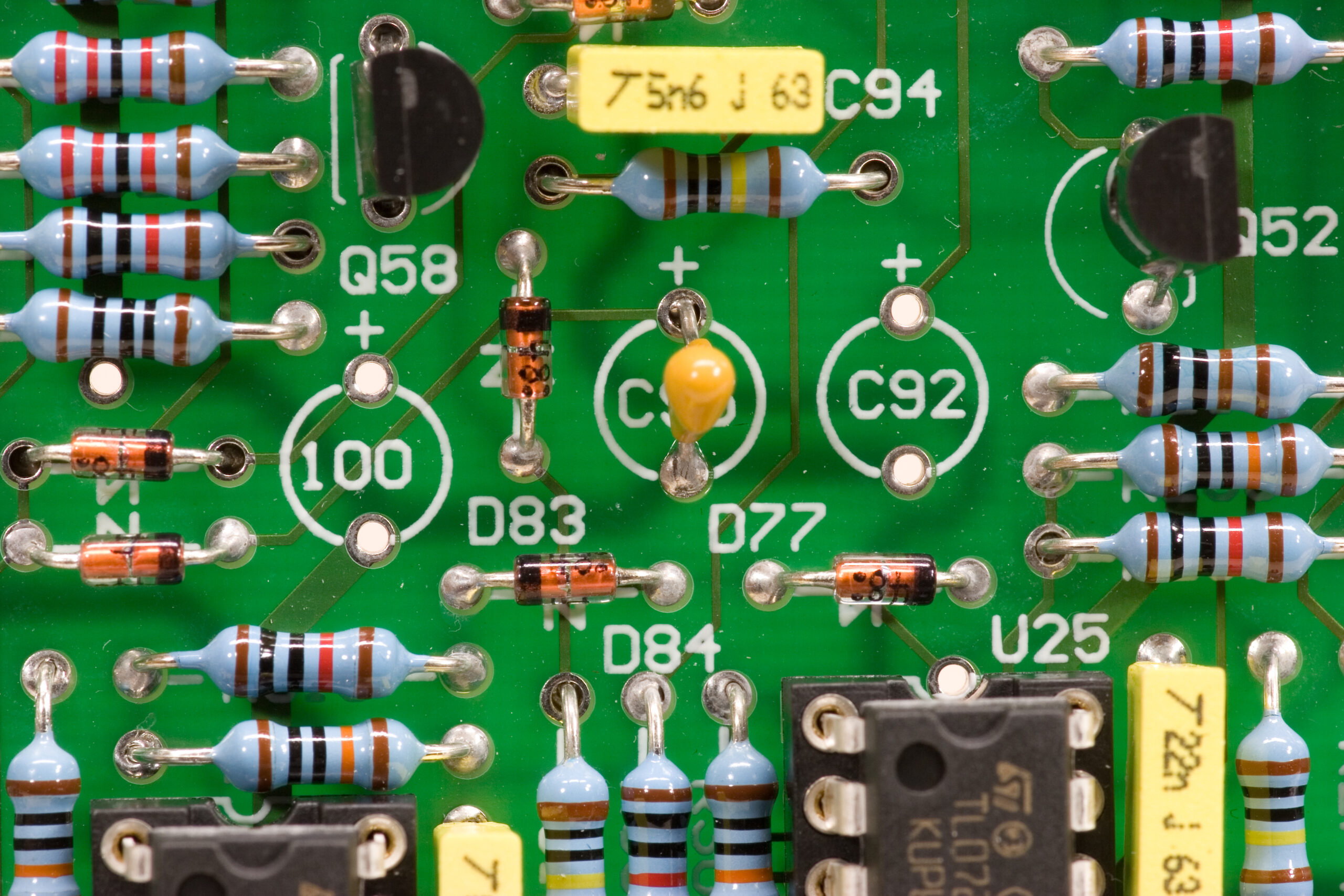
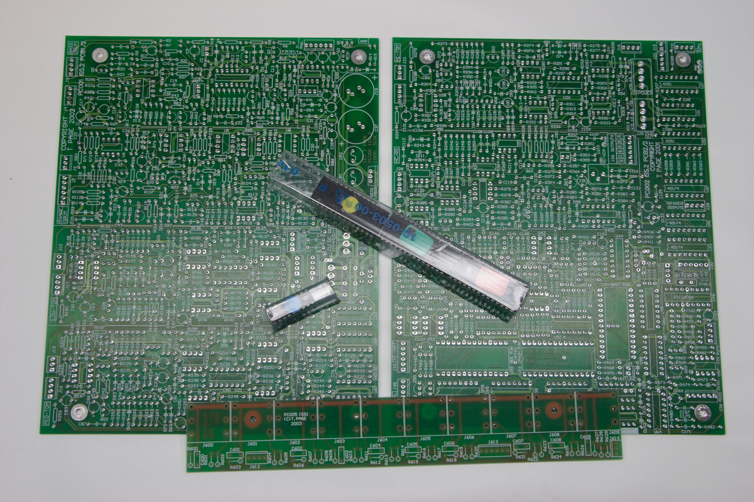
9090 PC001 Component Side — All Parts Fitted
(Click for solder side…)


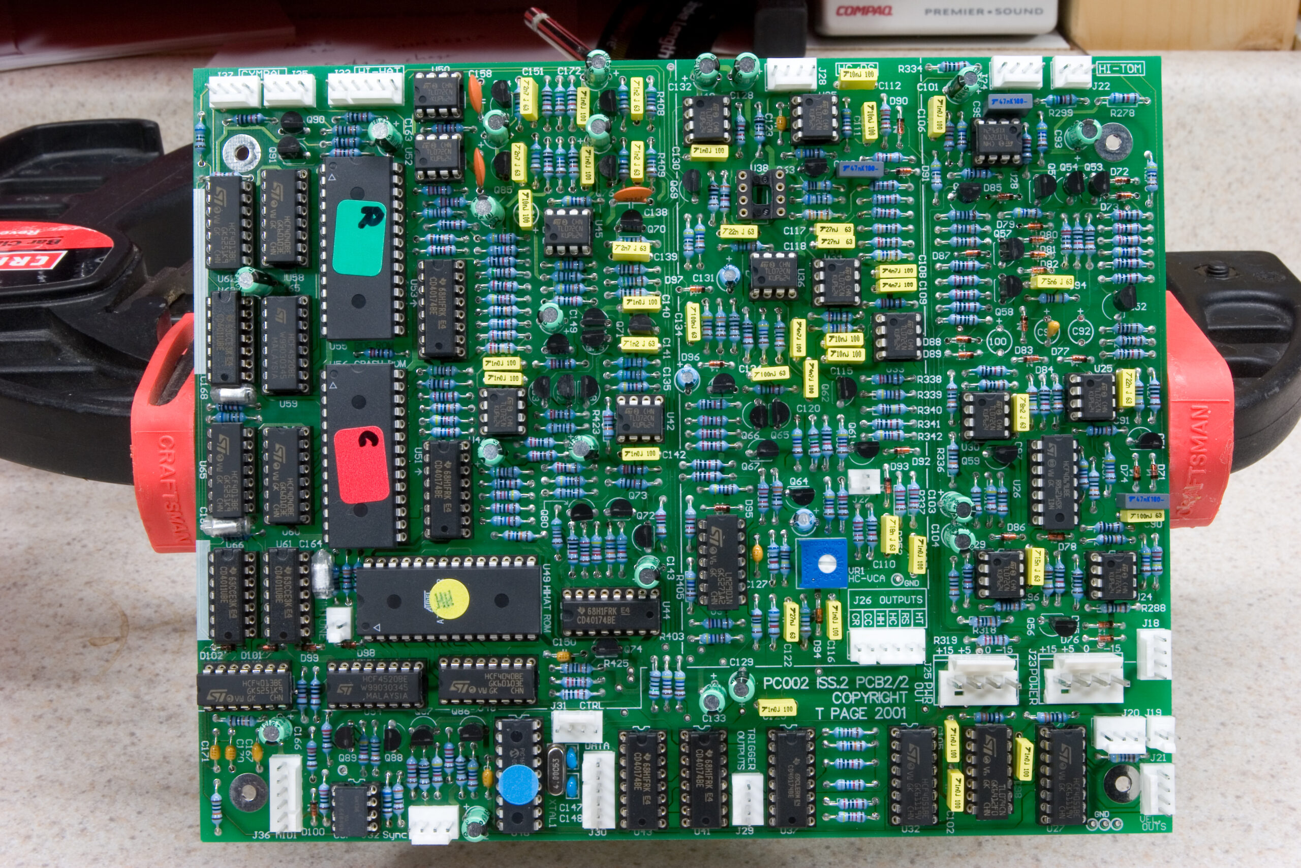
9090 PC002 Component Side — All Parts Fitted except U38, C92, and C100
(Click for solder side…)

Wow, I can’t believe it’s come this far. Starting a few months ago with a pile of PCBs and a couple of ROMs and a microcontroller I got to work building Trevor Page’s 9090, a clone of the sound creating bits inside the Roland TR-909.

I’ve been working on it here and there, ordering all the resistors one day, a bunch of caps another, etc. Except for my screwing up and failing to acquire (in the course of three separate rounds of ordering) enough .47uF electrolytic capacitors and an IC (CA3080) which I’m waiting to receive in the mail, the PCBs are complete.

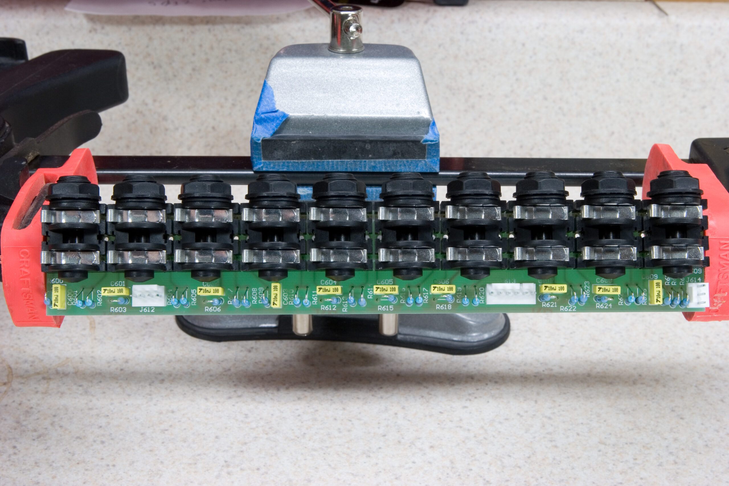
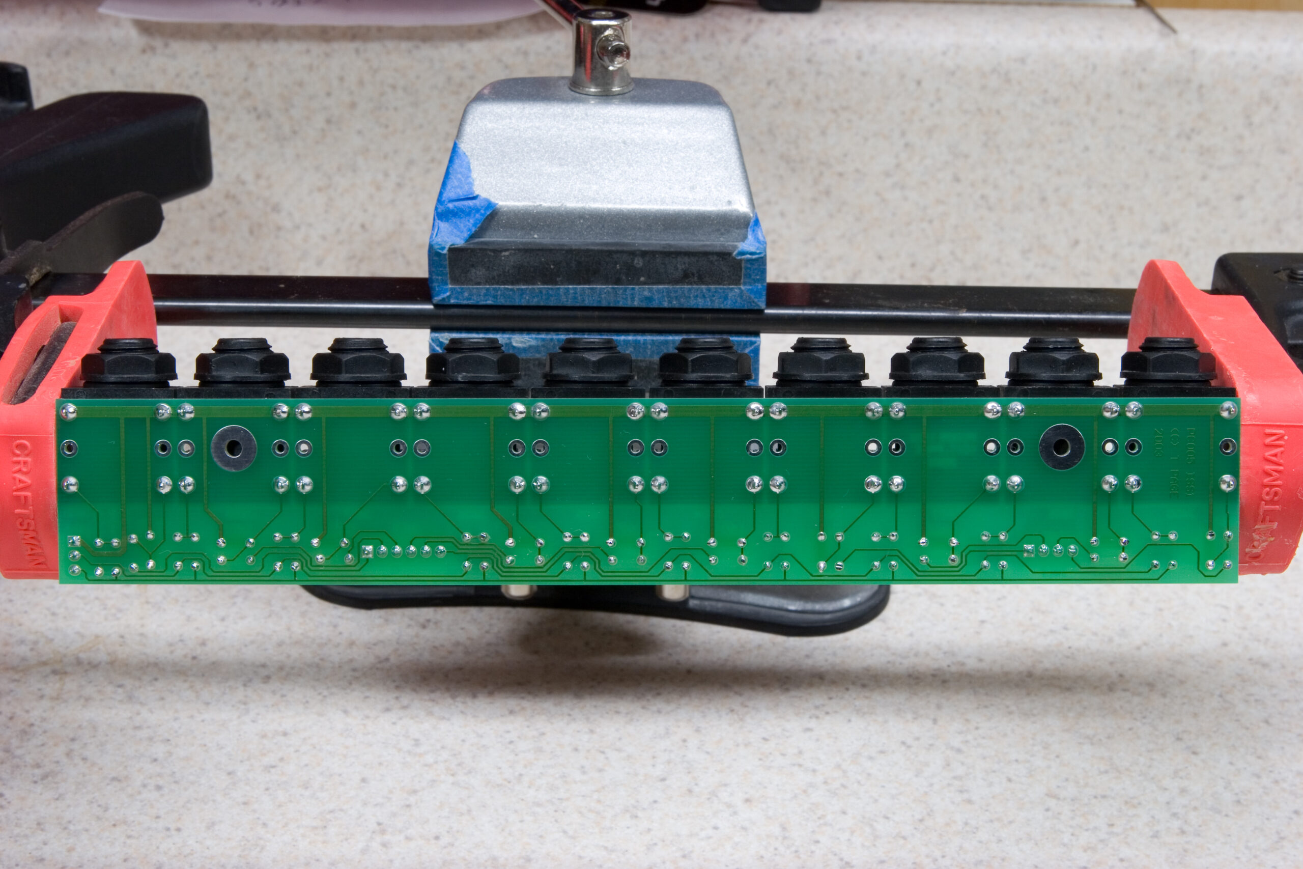
In addition to the two above, there is also a board with ten separate 1/4″ mono jacks which handles audio output for each of the ten separate instruments. The component side of that board can be seen here and the solder side here.

So, what’s left before it is done? Quite a bit, unfortunately. Let’s see…

· Get the missing three parts and fit them in place.
· Decide on an enclosure and design the front and rear panels so they fit the pots, knobs, LEDs, power switch, audio jacks, MIDI jacks, and mains connector.
· Order remaining parts.
· Design indicators / artwork and figure out the best way to apply / fit them.
· Cut the enclosure to fit all the externally-fitted components (pots, jacks, etc).
· Physically assemble the enclosure and mount the boards inside.
· Cable everything together.
· Test everything to be sure all instruments and switching jacks work as expected.
· Troubleshoot, if needed.

As you can see, there is quite a bit more to go, although I think this is a good stopping point for now.

electronicsmaking thingsmoved from livejournal

MAME Cabinet


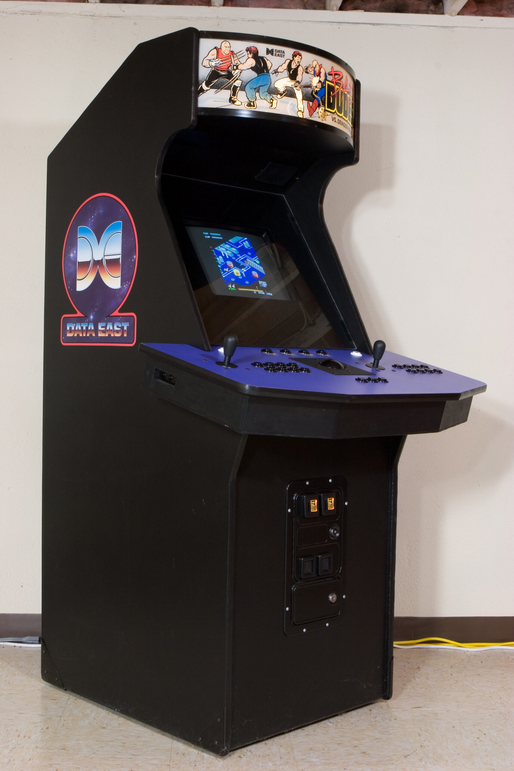
My MAME Cabinet over this past weekend, after I completed some general upgrades.
(Click for more MAME Cabinet (photo gallery retired) photos…)

Back in 2000 while still living at my parents house (this is both pre-apartment (photo gallery retired) and pre-condo) I ended up building a MAME Cabinet from scratch. (Yes, just a pile of wood.) While it has been in my basement, used on and off for years, I’d never taken the time to properly photograph it, nor write up anything about it. Well, now I did.

This past weekend I spent a fair amount of time on it, making a number of hardware and software changes, slightly upgrading MAME, moving to Compact Flash for storage, and generally cleaning it up. All in all, it looks like new again. Sure, it plays as it always has (read: excellent) but I feel as if I’ve rediscovered it.

After finishing up the upgrades I wrote up a (hopefully) complete document on my MAME Cabinet. This, along with high-res photos of it completed (photo gallery retired), high-res new photos (photo gallery retired), and the original webcam photos (photo gallery retired) have come together with loads of text to (hopefully) provide a good background on the cabinet, how it was built, and what it contains.

Tonight I still have to acquire the ~16GB of MAME ROMs I downloaded for it and process them so that I can properly pick from as inclusive of a list as possible for play, but this should only take some time. And while it’s downloading I can play some Bubble Bobble. Or Ms. Pac Man. Or Asteroids. Or Capcom Bowling. Or Gal’s Panic. Or Dig Dig. Or…

gamesmaking thingsmoved from livejournal

MAME Cabinet

So… My MAME cabinet is working great again. It’s at the point where I just have to finish the physical clean-up, resoldering of some connections in the control panel, and photography. As hinted at, I might snag a 27″ VGA monitor for it, but… I probably can’t spend the $600 right now. After all, I just ended up spending a bunch on fisheye camera lenses (Peleng 8mm, if anyone is curious).

gamesmaking thingsmoved from livejournal

iSight Car Mount

I know this is old news, but I finally banged together a page about my iSight Car Mount.

There are embedded videos of the tests I did, both driving around a bit and a stop-motion video of my drive to work.

And yes, this is related to the silly Flash question I had earlier. I was able to find a newer version of the player which has a click-to-play button available, so that should a noisy video be clicked on my the user, it doesn’t immediately deafen them.

I think there is still a lot to do with Gallery and it’s video support, and I need to figure out a better way to transcode files consistently and add hinting needed for lighttpd’s flv streaming support.

But, for now, it works. :)

automotivemaking thingsmoved from livejournal

110 Slide / 35mm Negative Scanning & Custom Cables

Well, I finally started something and finished it! Earlier today I began writing up a overview of how I’ve been handling scanning my 110 slides and 35mm negatives. It’s still in a sort-of rough draft state, but all the photos are there and such. So, if you are interested in how I’ve been handling the scanning, along with enough info to do it yourself in a similar way, go ahead and give this article a read:

· 110 Slide / 35mm Negative Scanning

I also spent a bit of time putting together info about the materials and such which I use for making custom audio and video cables. It currently only covers component video cables, iPod connectors, and subwoofer cables. More info will come later. The article can be found here:

· Custom Cables

It’s nice to feel as if I’ve finally managed to get something done.

UPDATE: Also, please digg this story.

electronicsmaking thingsmoved from livejournal