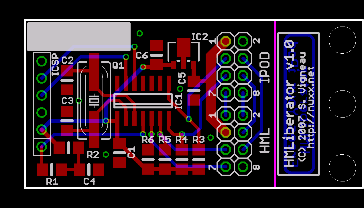
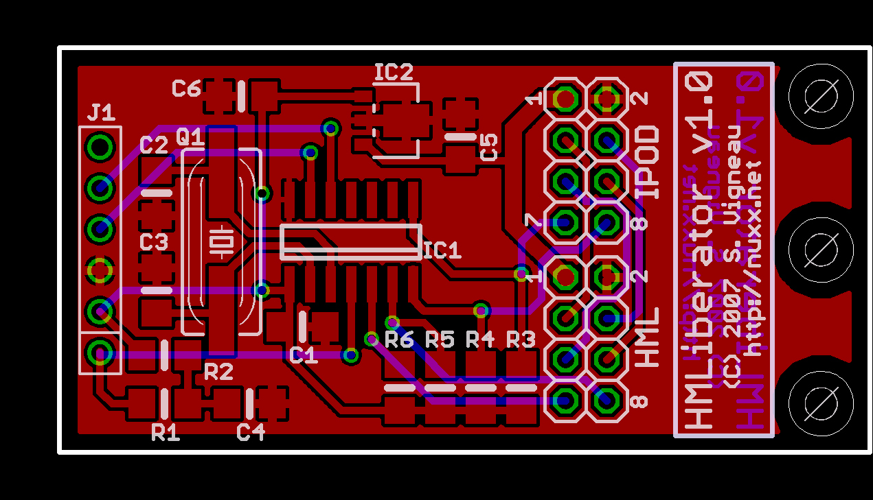
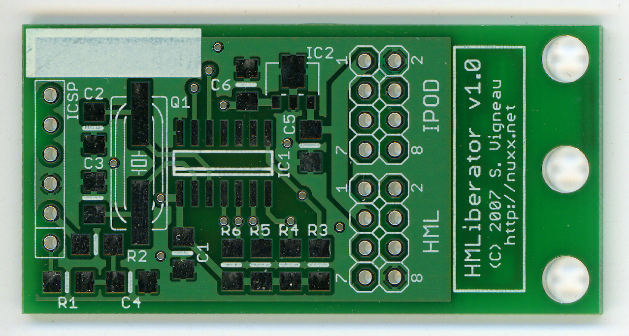
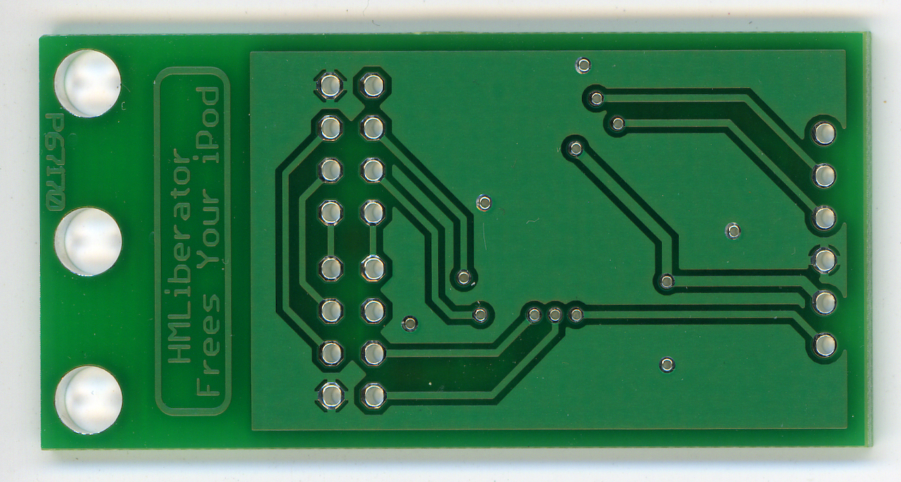
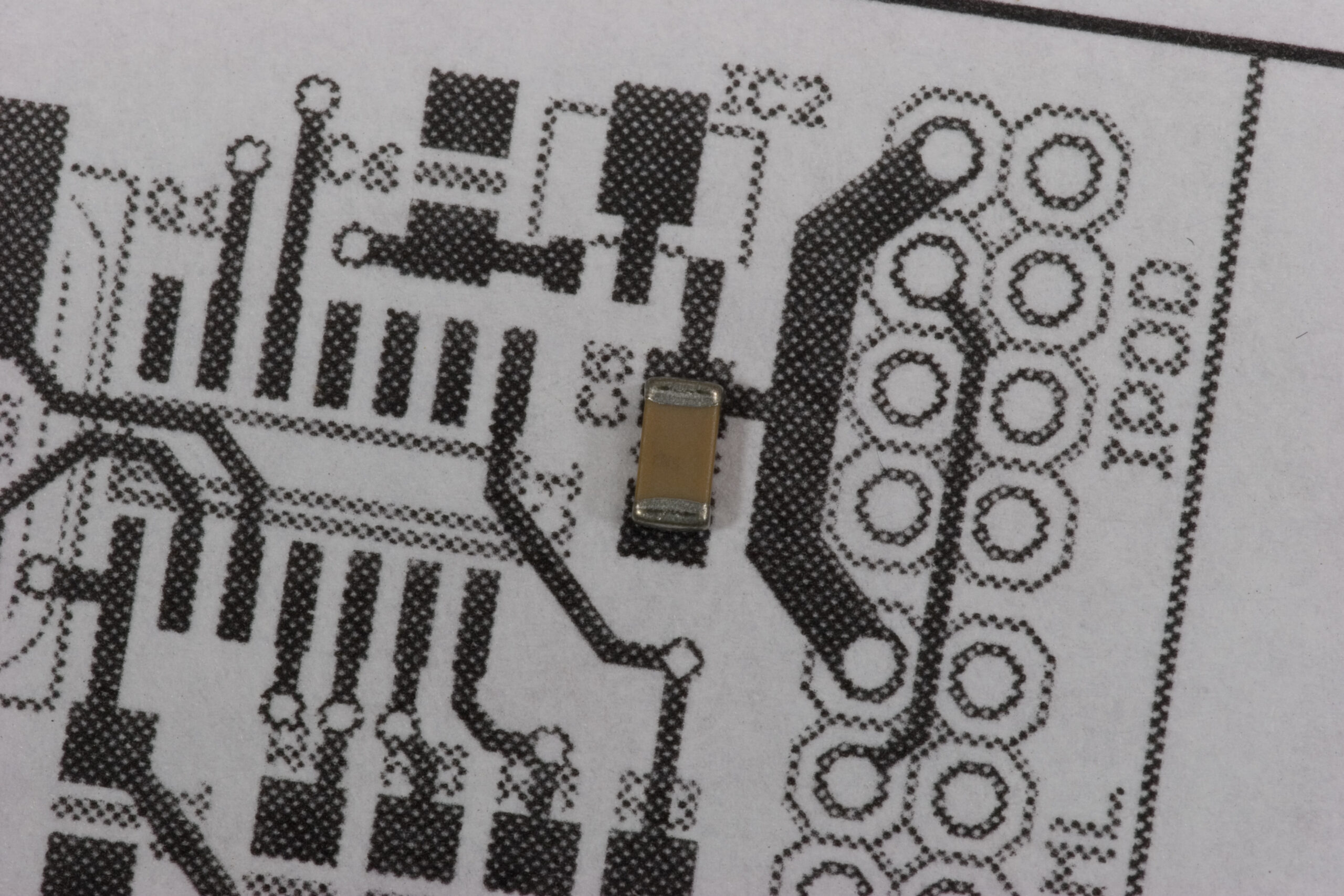
 HMLiberator PCB v1.0
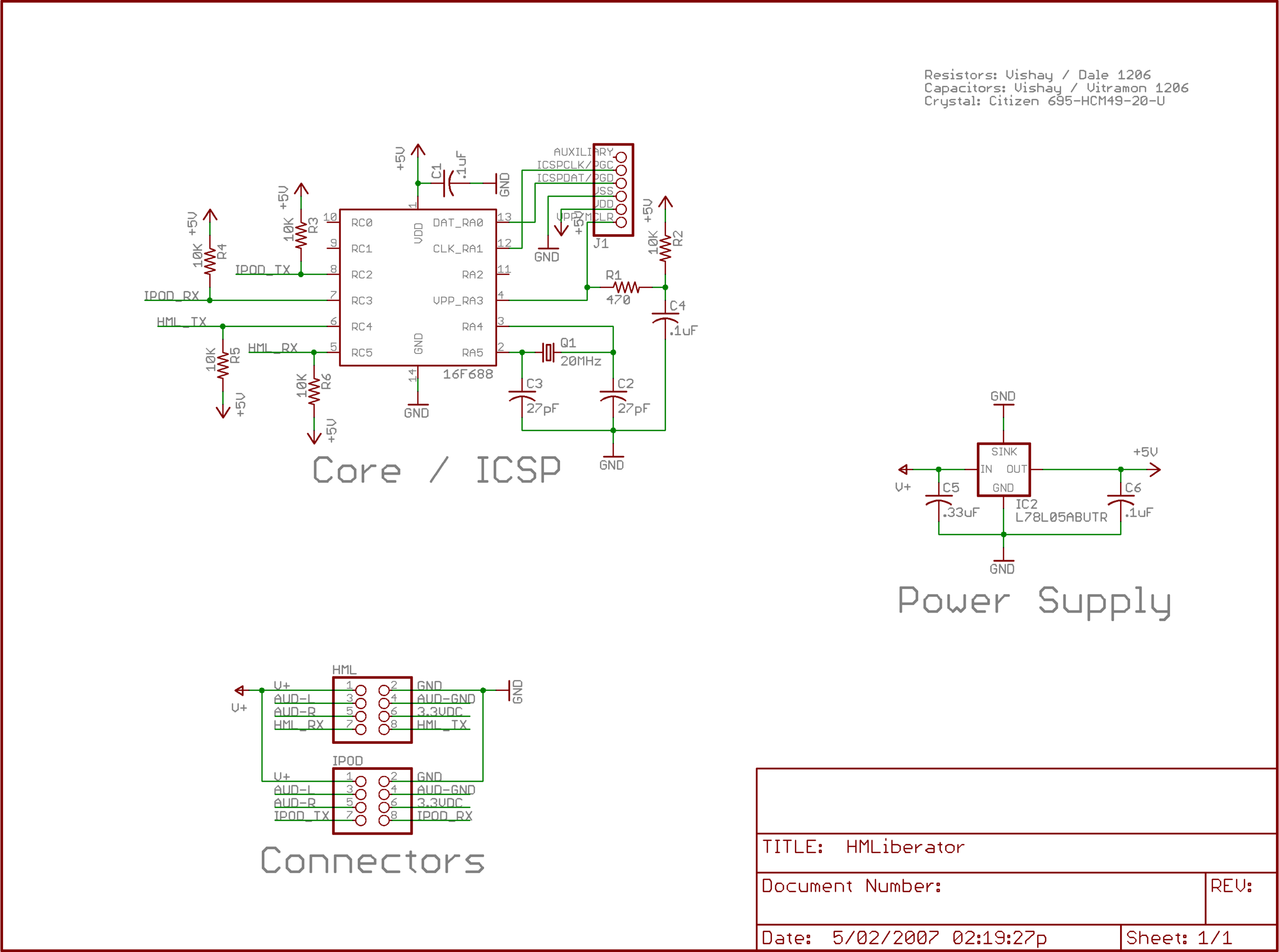
(Click for 600dpi version.)
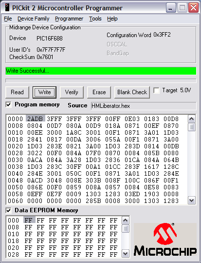
Well, it’s done. I’ve ordered the first run of PCBs for the HMLiberator. While they are technically a prototype, these v1.0 PCBs should be also be usable as the final part. The circuit is pretty simple, and I’ve checked things over a number of times, and it all seems right. Now I just need to finish the software.
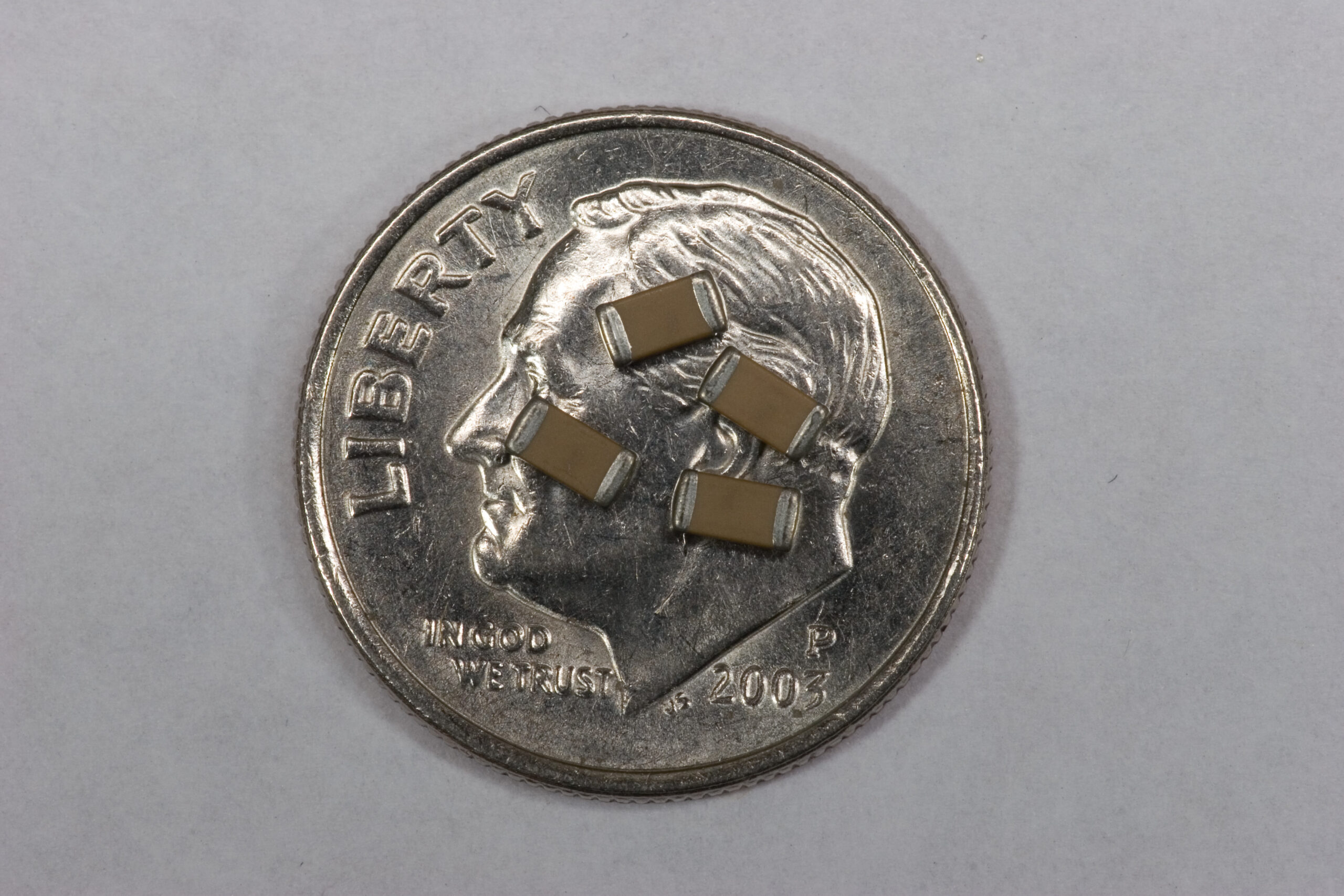
Thanks to Advanced Circuit’s $500 Free Promotion I was able to get a $500 credit towards one or two orders, making this entire order free. I’ve heard excellent things about Advanced Circuits, and due to the small tolerances on these boards I wanted to be sure they’d be done right. Also, should I go production on this item, 250 boards will only cost $1.94 each.
For now I ordered 12 boards, as any quantity from 5 to 12 were the same total price (price per board * quantity). With any luck I’ll have them by the weekend, or maybe early next week. Until then I can just finish polishing the software.
If you are interested, the schematic is available in black and white or color. I’ve also uploaded another file containing the Gerbers and CADsoft EAGLE files, should anyone be interested in them.
Now, to get back to normal work, and possibly update the online documentation for the project a bit later. I also should make a post about Saturday, which was a really nice day of beer brewing, friends, and beer in the evening. (Although I think a bit too much beer… or maybe too much Mt. Gay afterwards at ‘s place.)
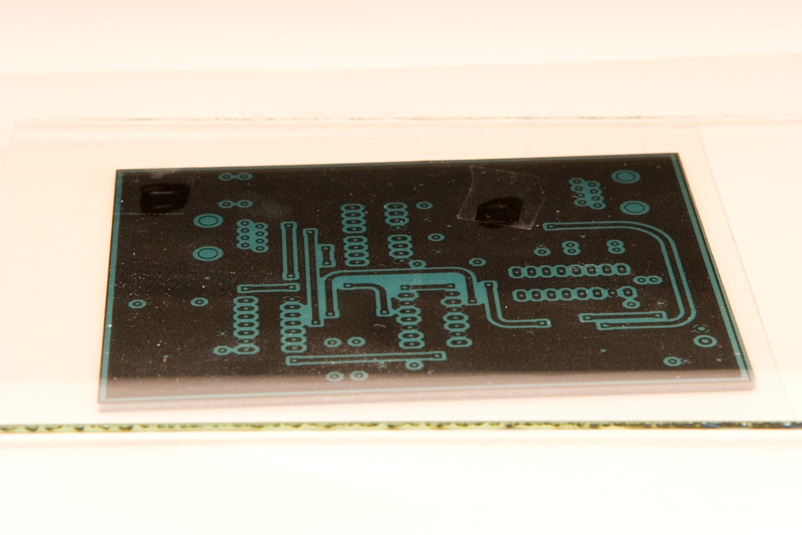
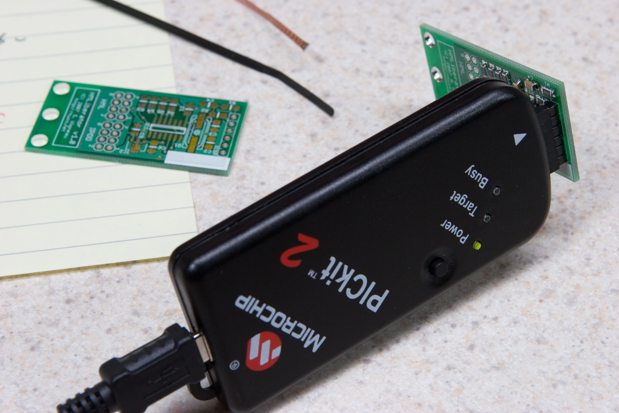
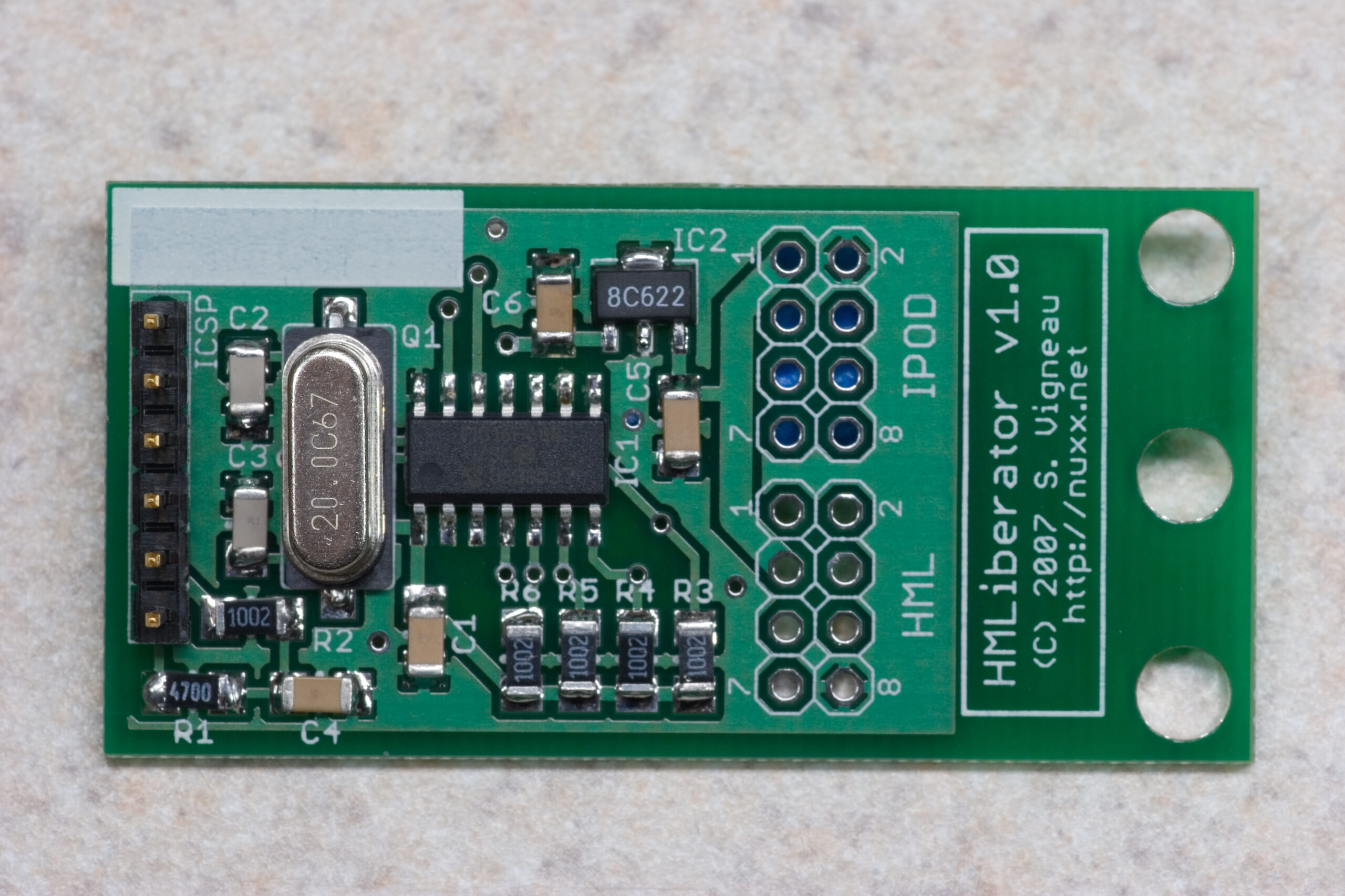 HMLiberator v1.0 PCB complete, except for cables.
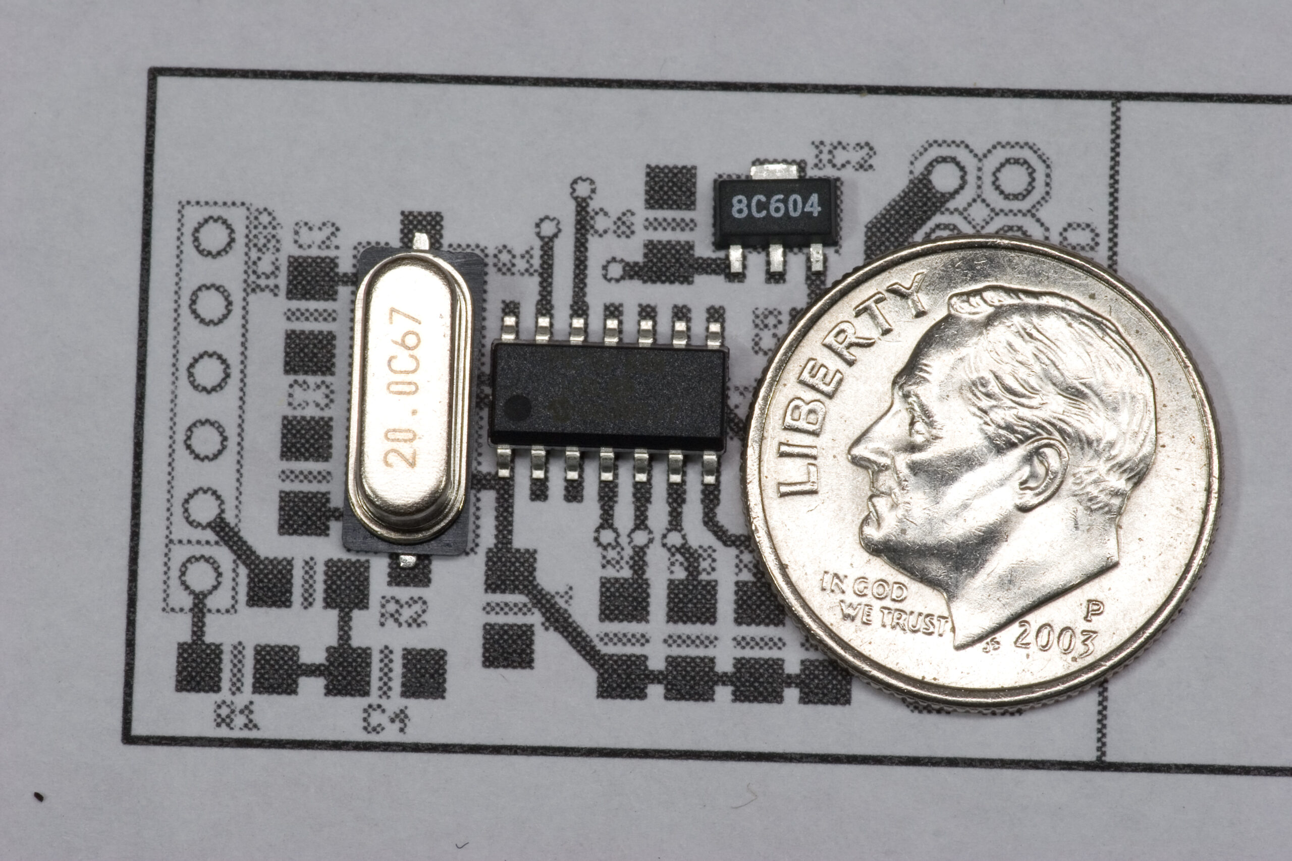
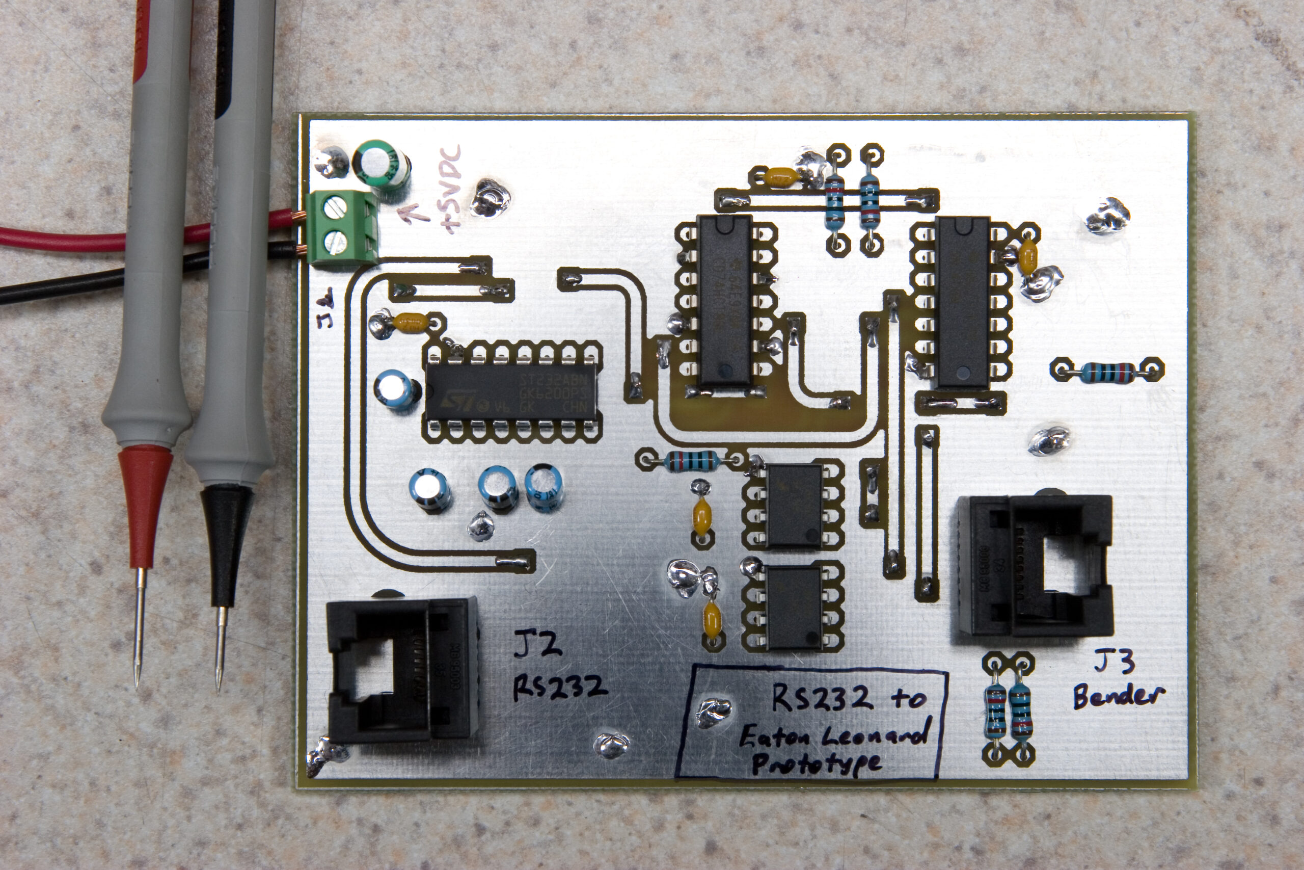
 Working on the HMLiberator
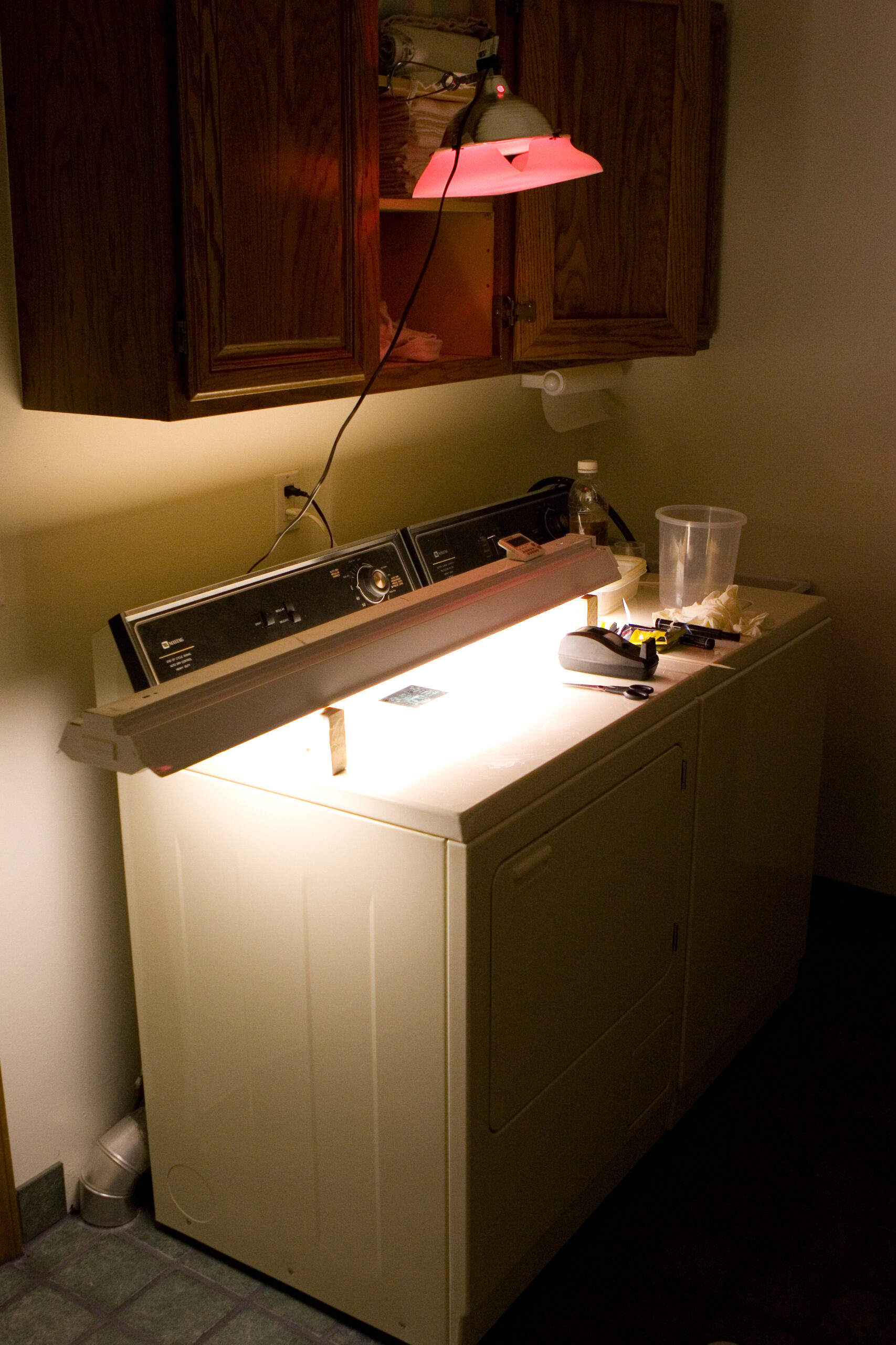