P3 MemX
August 30, 2007
Yay! The Sequentix P3 MemX board came in today. That means I can install it and then get the auction listed. Maybe I can get it listed Sunday on a 10-day for closing sometime the following week.
Yay! The Sequentix P3 MemX board came in today. That means I can install it and then get the auction listed. Maybe I can get it listed Sunday on a 10-day for closing sometime the following week.
Yesterday I picked up another SCPH-1001, OEM controller, and two third-party controllers. Inside of one of the third party controllers is a larger-than-the-Sony IC for converting button presses to the Playstation controller protocol. (The other is completely potted.)
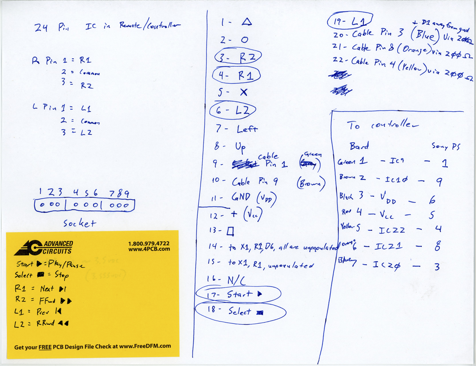
I’m going to document that board (it’s very simple and not all the pins on the chip are used) and hopefully lift the chip and place it on a new, smaller board which I’ll make up. On this board I can leave large enough pads to solder to so that I don’t have the problem I had last time. Well, the soldering problem… The root of the problem is because I documented the Sony controller at around midnight, then didn’t double-check that documentation yesterday. I had counted some pins wrong. :(
I also have to rip out the shiny cabling that I put in place the other day and replace it with… whatever the new stuff is. I might also use random salvaged flat cable to save headaches, or just some de-jacketed CAT5. I’m not sure about this yet.
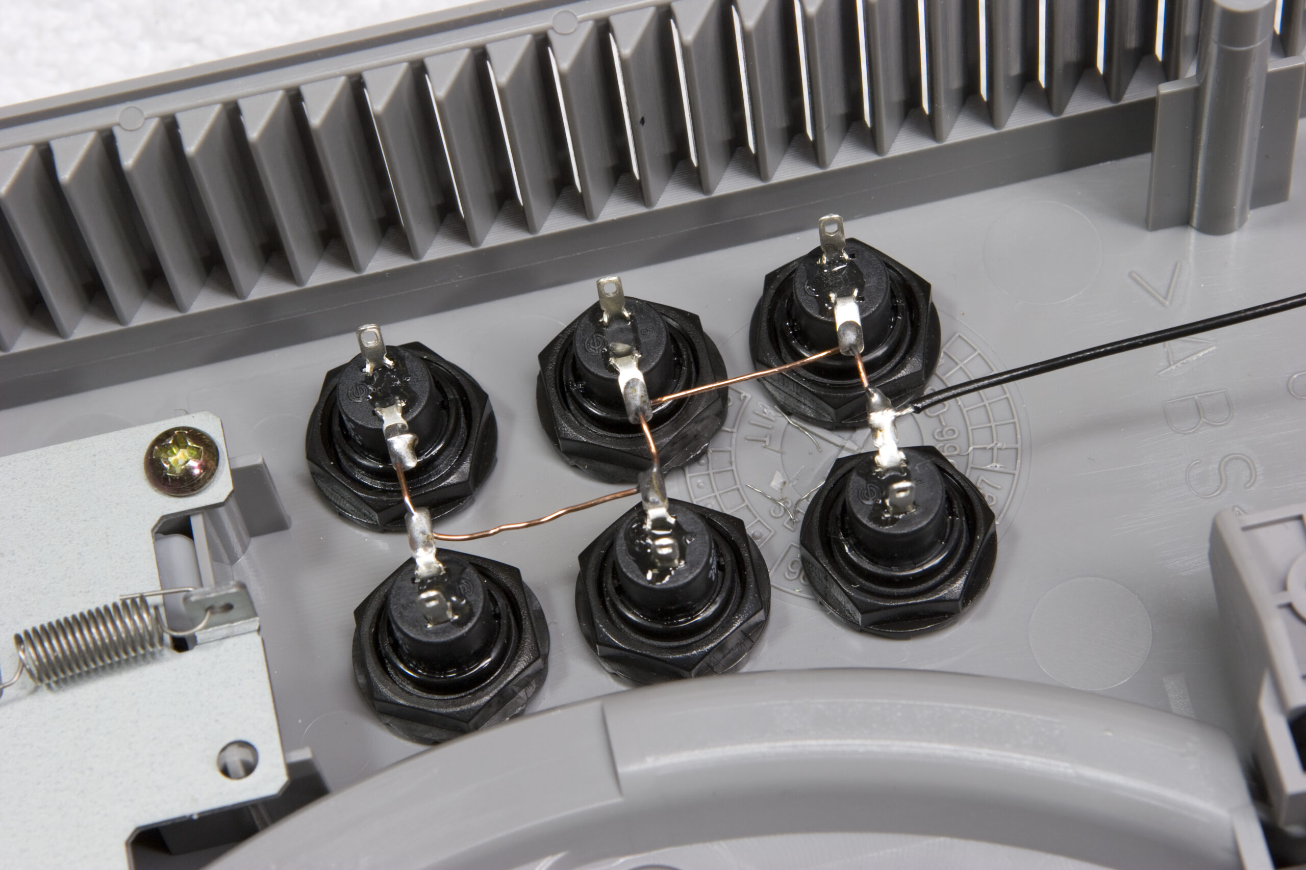
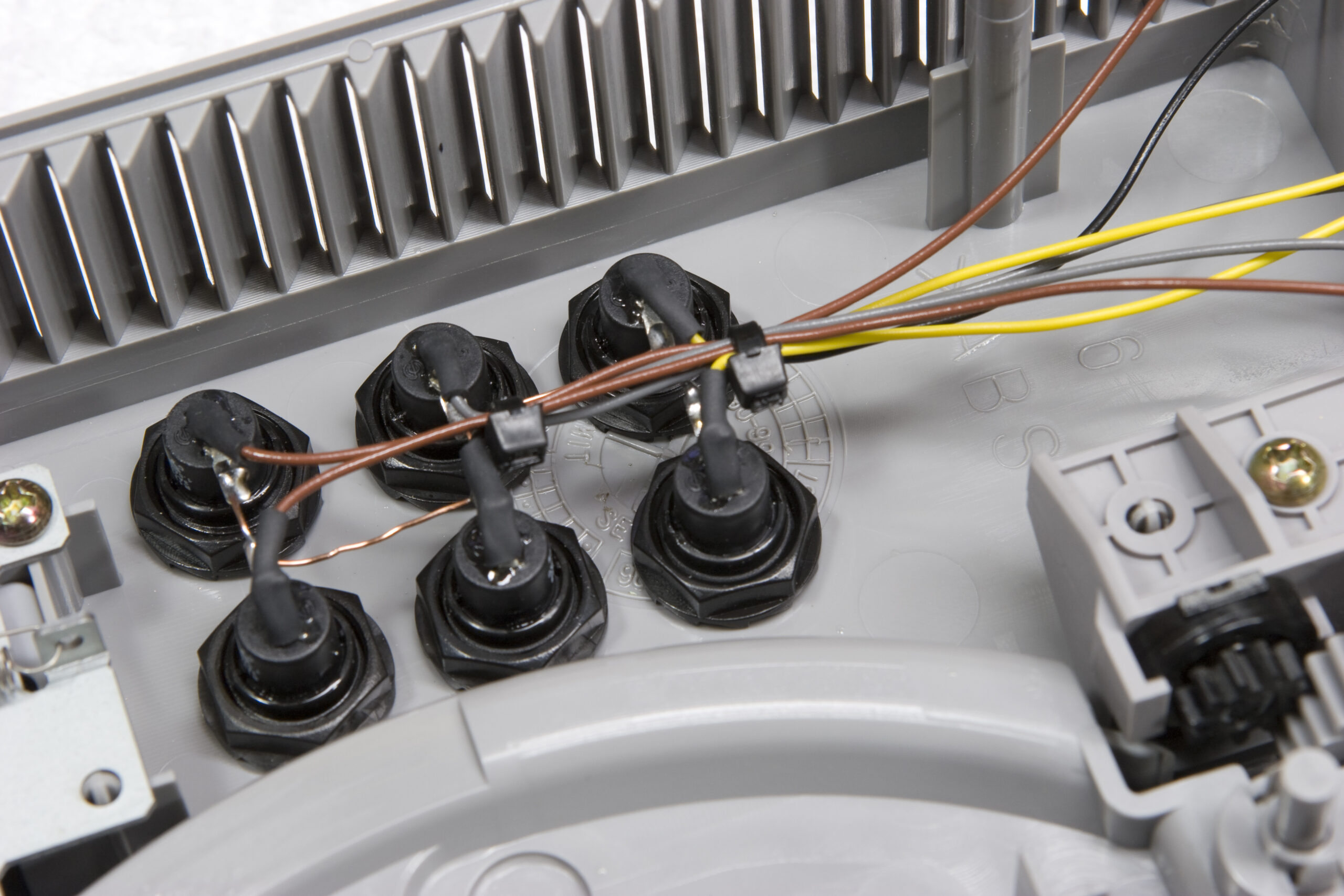
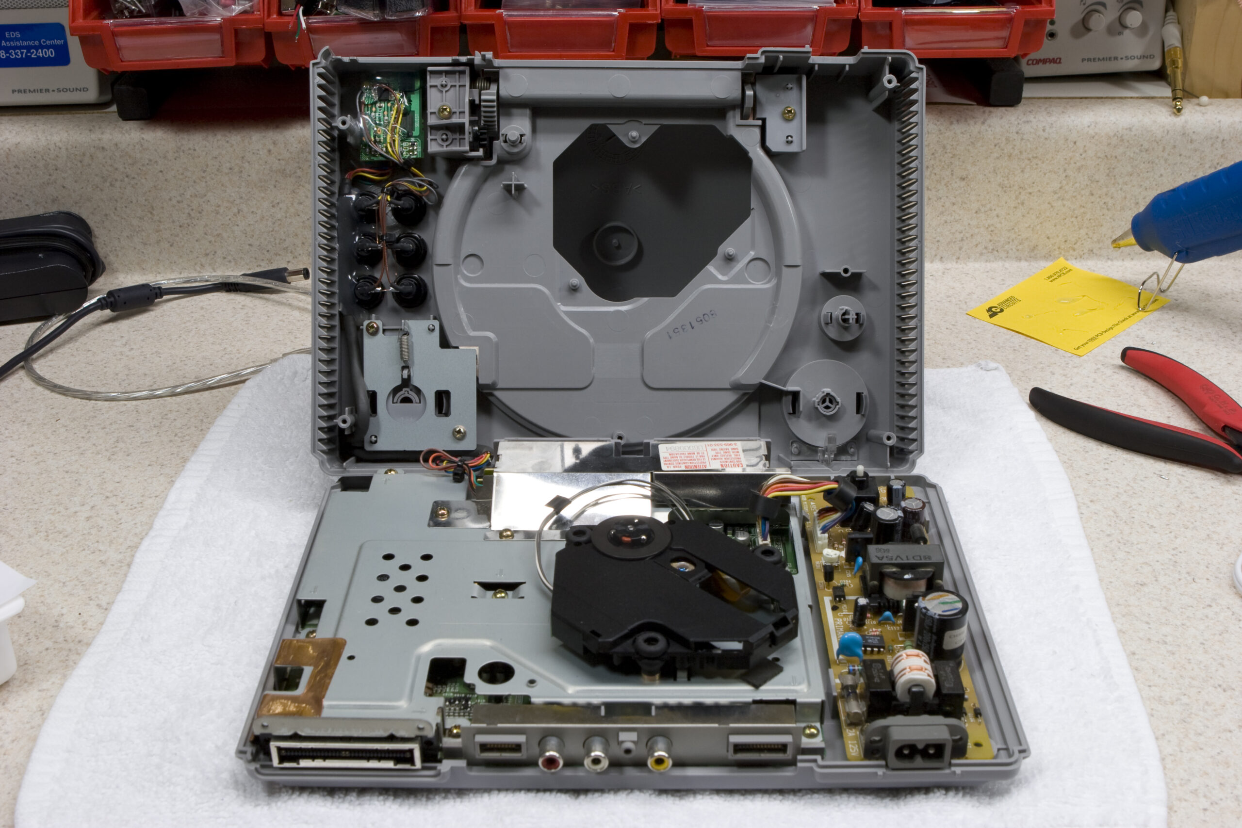
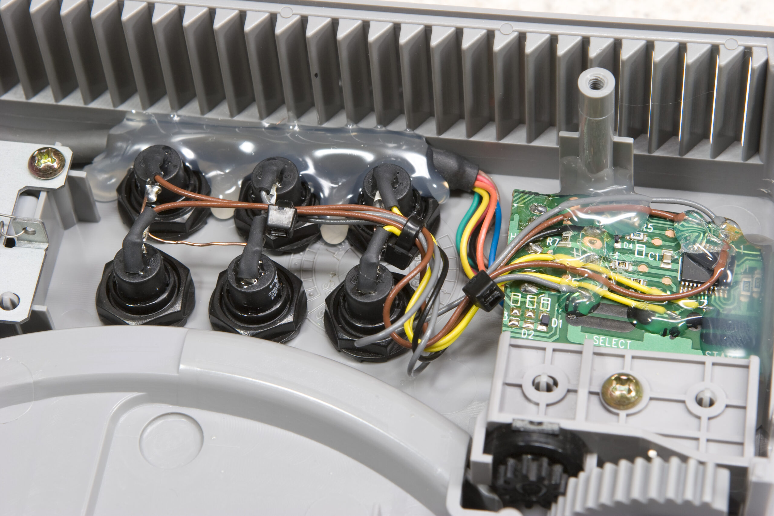 Cut Down SCPH-1080 PCB and Pushbuttons
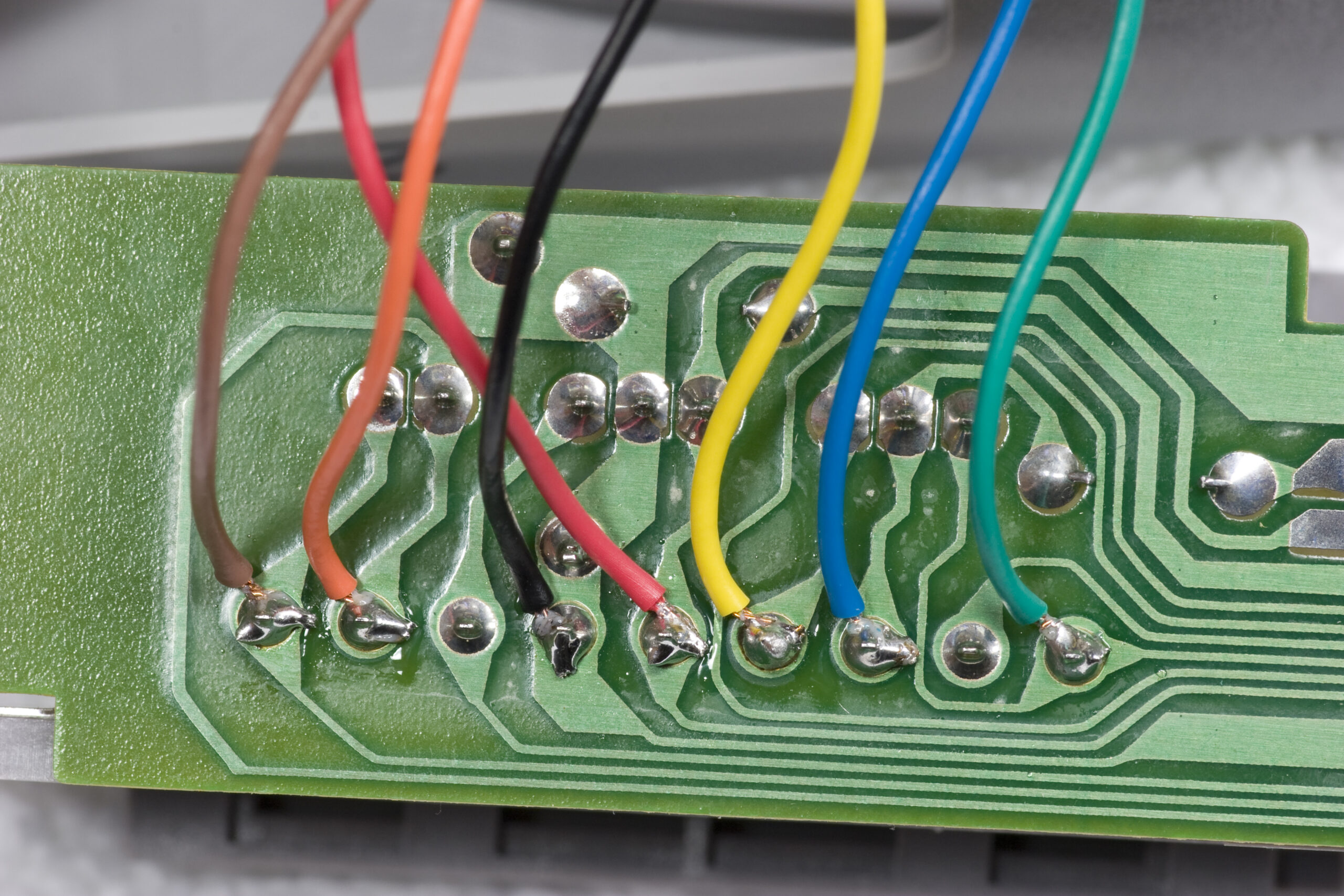
Last night I spent a while cleaning the plastics on the SCPH-1001 that I was putting buttons in, reassembled the lid and closing mechanism, mounted the buttons and ground bus, wired up the signal lines, connected the signal lines to the pcb, and… screwed up. I’m not completely sure where I went wrong yet, but I *think* I miscounted the pins on the IC late last night when making up these notes, and possibly counted pins wrong. I still haven’t figured out what is wrong, but I think this is where things are off.
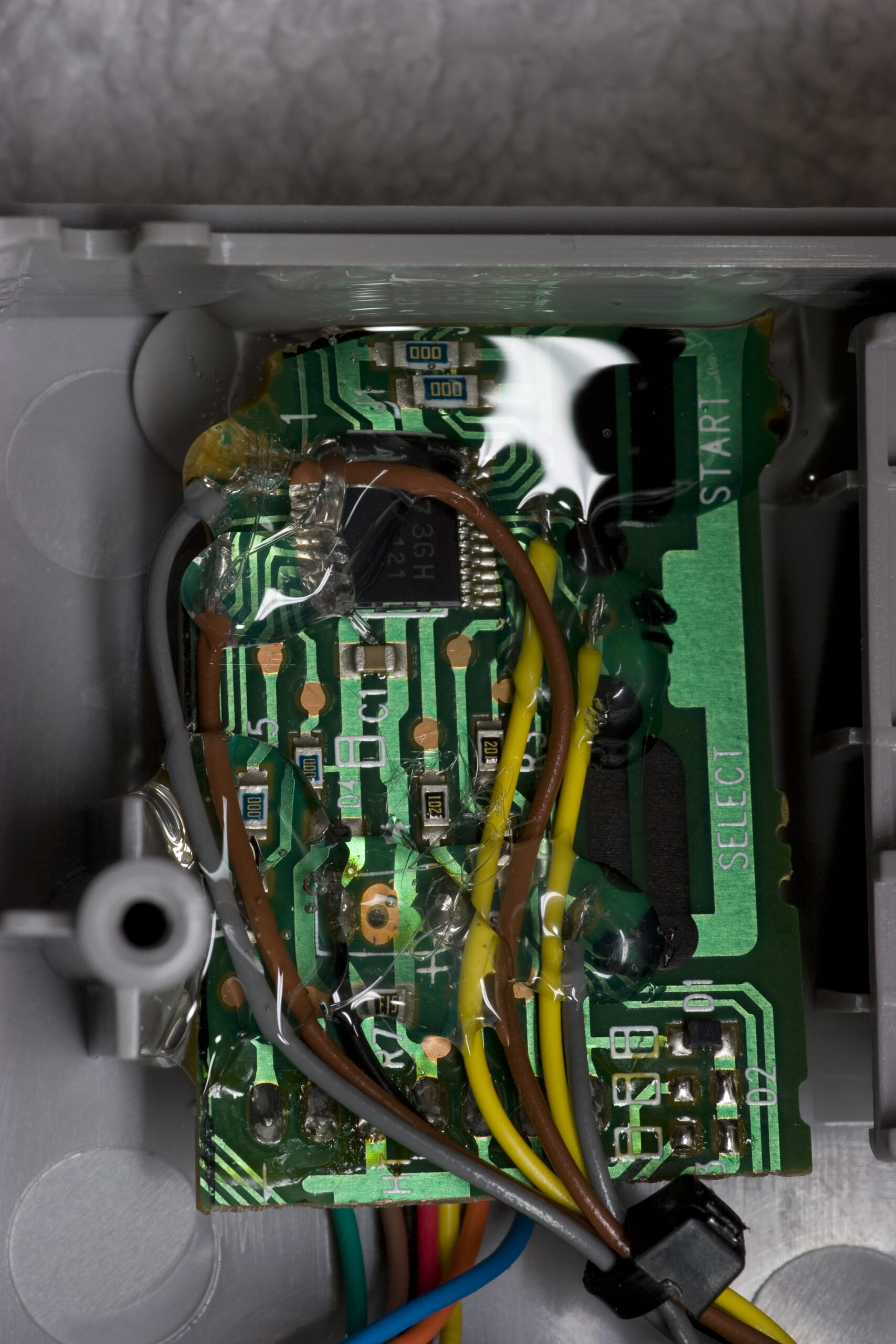
I confirmed that the connection to the rear of the controller jack is right, and things connect right to the PCB. I don’t see a short between any of the signal lines, and the Playstation does boot to the CD player screen without error. So, I’m kinda thinking I screwed up something with the PCB. I’m just a bit frustrated because I secured the wires to the board and then secured the PCB into the enclosure with hot melt glue. It’ll be a hassle to rip out, and I won’t be able to reuse the PCB. That means I’ll have to find another Playstation controller. Oh well. :(
And here I was quite happy over how it had all fit into the enclosure. I’ll just have to work on it a bit more, I guess.
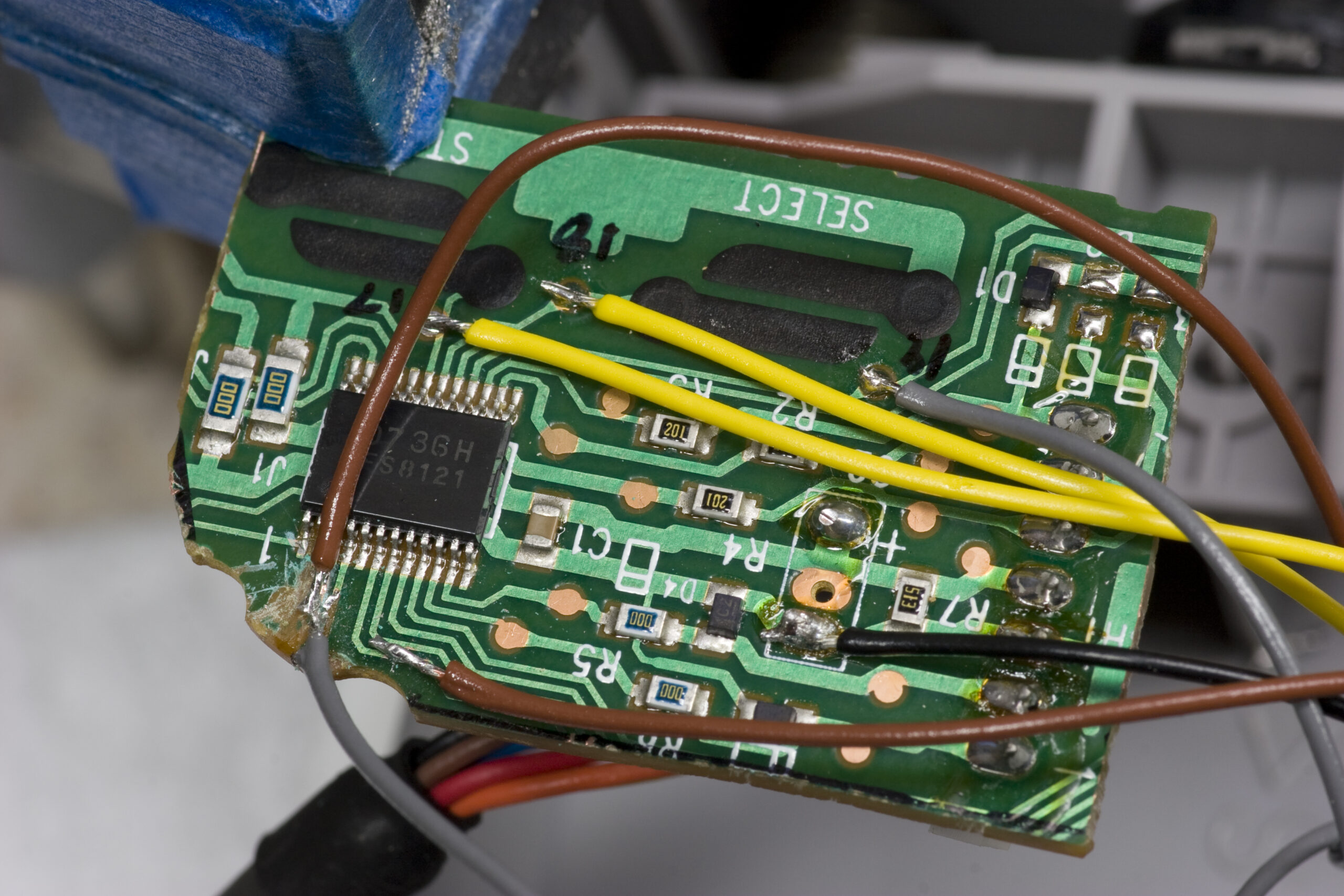
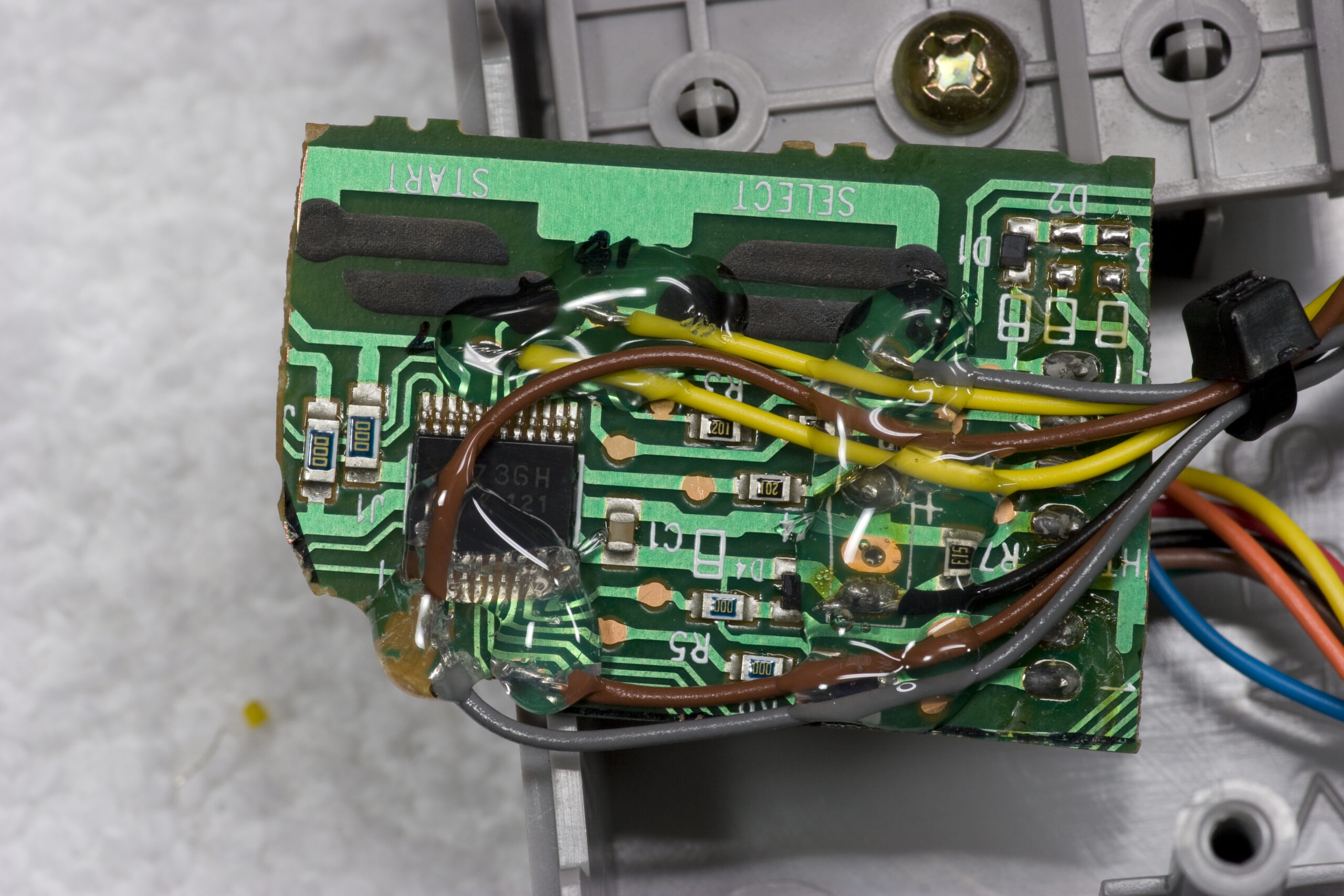
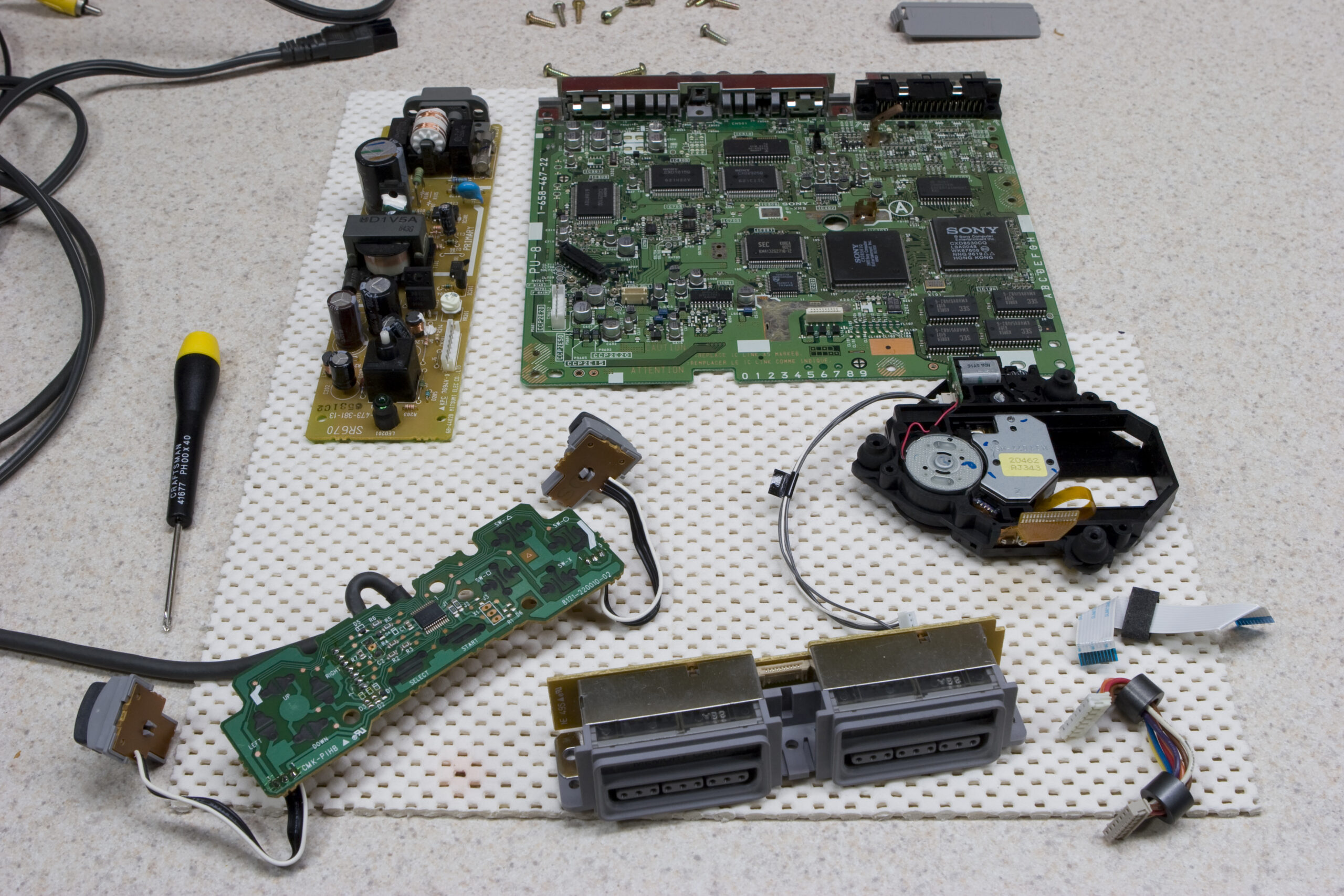
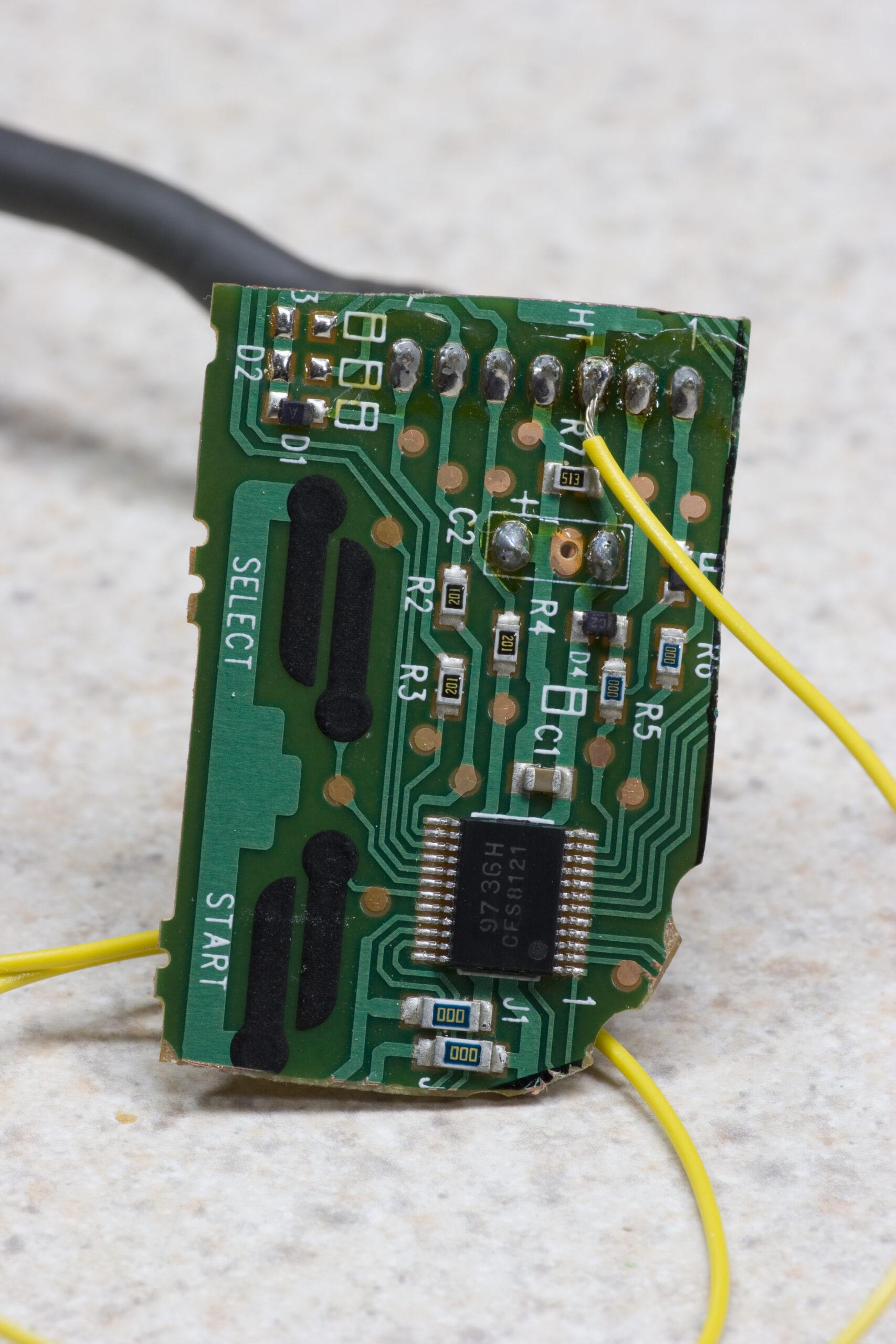 SCPH-1080 Playstation Controller PCB, Cut To Size, With Test Wire
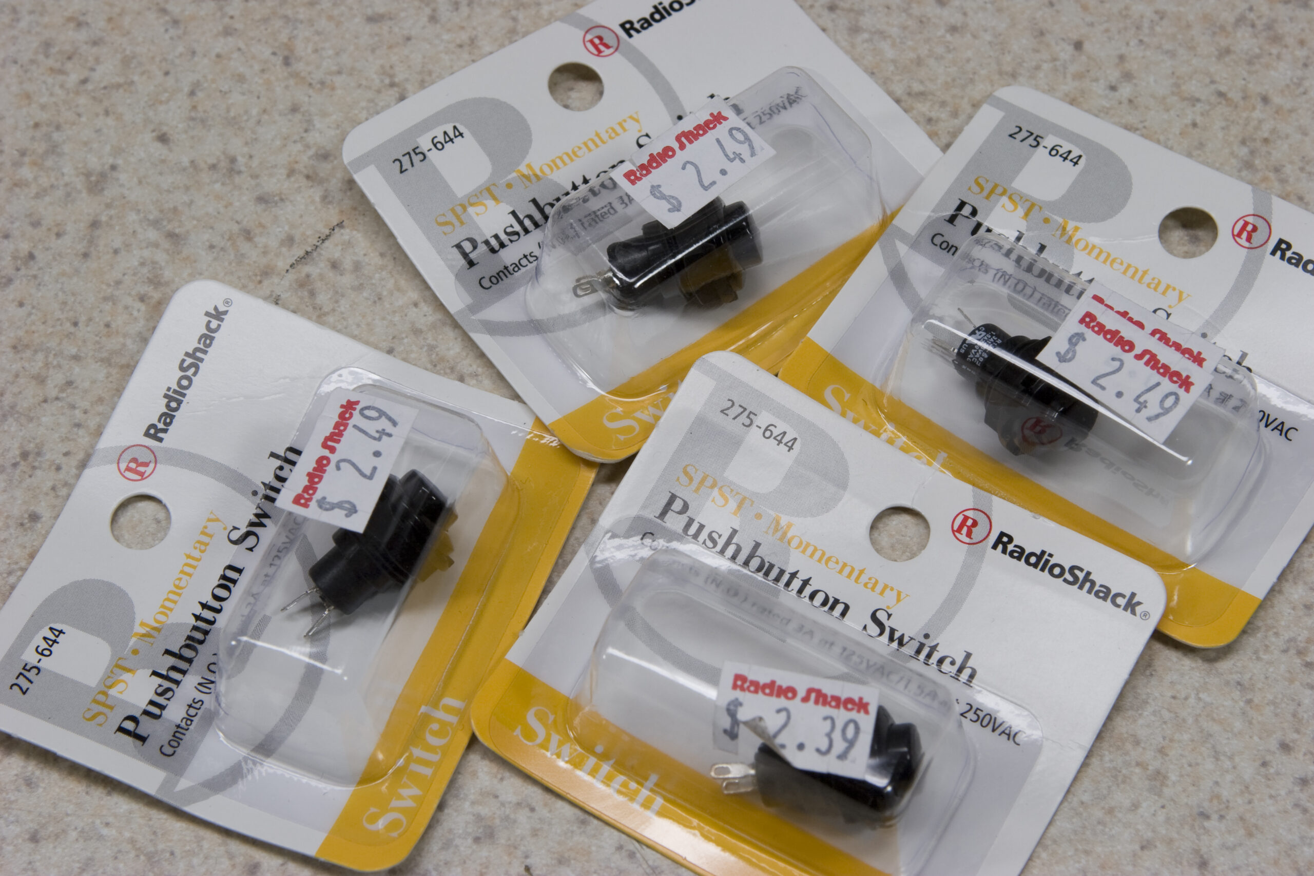
A little while back I posted something which showed me using a SCPH-1001 Playstation as a CD player with my recently completedMillett Hybrid Maxed headphone amp. Well, after taking the SCPH-1001 apart over the weekend I picked up some overpriced buttons from Radio Shack (so I could get started on things today) and… got to work on it.
I don’t have much to say yet, as I’m only about half-way done, but I think it should work. Basically, I’m taking the PCB from inside a controller, cutting it down to around the minimum needed (as seen above), and wiring it up to some buttons on the top of the case to act as the controller buttons needed for CD playing. The buttons will be Play/Pause, Stop, Prev Track, Next Track, Rewind, Fast Forward.
Yes, it’s a massive hack, and I normally don’t like the cutting-down-the-PCB idea, but I just wanted this done quickly and cheaply. I thought about lifting that IC and making my own board for it, but that wouldn’t provide any benefit, and would just be more effort. So, I’m doing it this way.
More pictures of this can be found here (photo gallery retired). Tomorrow I’m hoping to finish it up, and I think it’ll be possible. I’ll post more photos and maybe do one of my cheesey project writeups then.
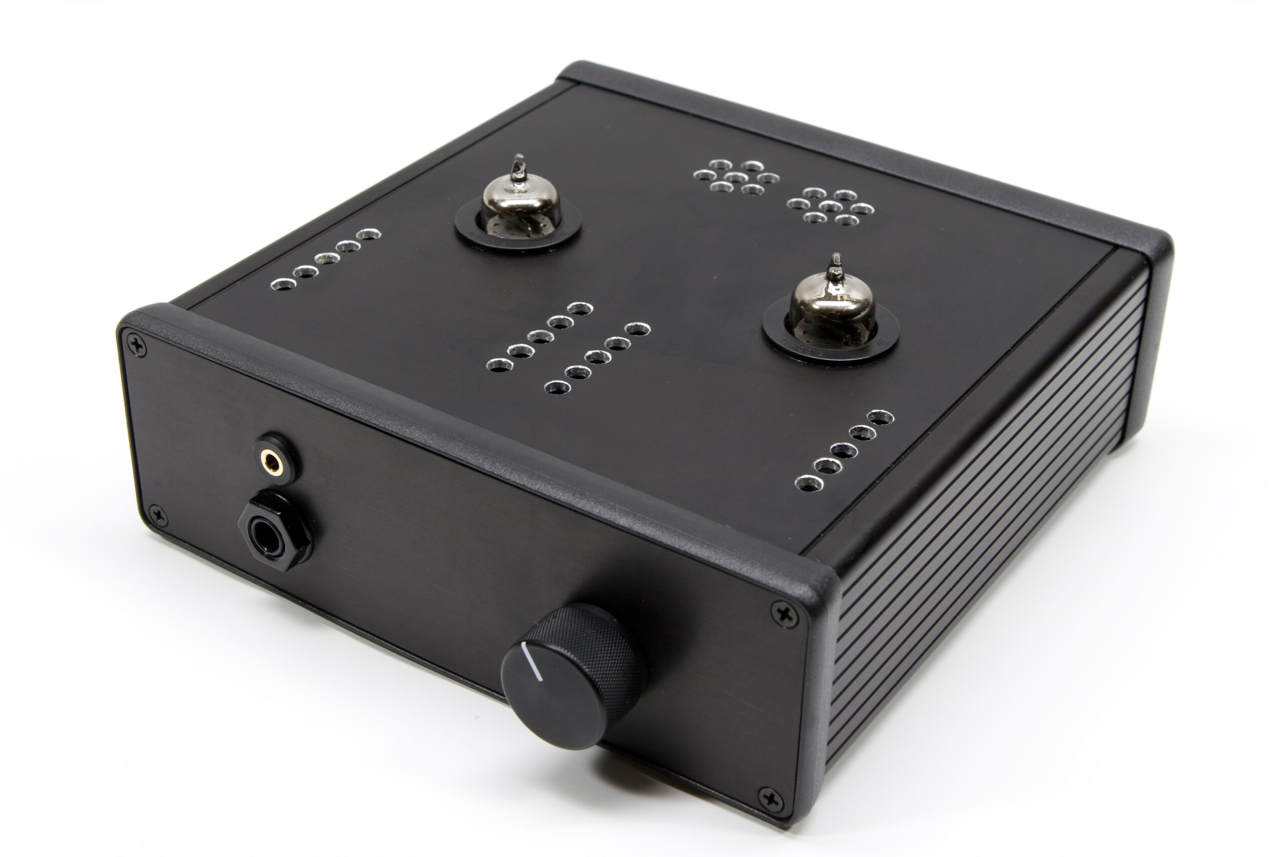 |
My Completed Millett Hybrid Maxed
(Click for my write-up…)
Well, I finally (mostly) finished my brief writeup / overview of my building of the Millett Hybrid Maxed tube-based headphone amplifier. It covers info about the parts I used, including knobs, case, jacks, plugs, etc. I also wrote up a bit about the issues I experienced in building it.
I still have to add thermal information and maybe a section covering current requirements powering on from cold, etc. Still, as it is things are pretty complete.
Also, my x0xb0x sold for $890 last night, to someone in Australia. Turns out that person knows the person in Oz who I helped build up the MIDIbox SID-NUXX. DIY synth stuffs really is a small world. Now I just need to wait for the MemX expansion for my P3 to arrive so I can install it and then list the P3 up on eBay.
You all remember the MIDIbox SID-NUXX, right? Well, as I mentioned previously someone was selling something with a board of mine in it.
I posted about this here at the MIDIbox forums to inform people of it and hopefully get some assistance. (You’ll have to read the whole thread to get it. It is initially supportive.)
So, what happened after the posting? I’ve been essentially shouted down and told, both in private email, private forum messages, and normal forum messages that it’s my fault that it happend, and I am wholly responsible for the problem and for stopping it. I don’t quite understand this response, as I spent a bunch of time and money putting a new design in place, licensed the portions of it which I created properly (creative commons, non-commercial, share alike), and then gave it all away for anyone to use. Net cost? Probably around $1K out of pocket and a bunch of time.
At this point I’ve tried contacting eBay, who has told me that the claim about the board in there being my IP is “uncertain” and not yet replied when I provided additional info†. I asked for help from the community and was told that it’s my problem and I owe it to them to fix it. I’ve talked to the seller both via eBay and direct personal email (Flavio Mireles) and he’s played dumb. I’ve even tried bidding it high myself on eBay both with my personal account and sockpuppet accounts, and those bids have been cancelled. (Probably because the person saw new users and then my username in the bidding.)
I’m not sure what else I can do at this point, so I’ve gone ahead and pulled all the real-value contributions I made down. That is, the PCB CAD files, photoplotter/drill files (Gerbers and Excellon drill files), MIDIbox SID-NUXX-specific software binaries, all of that. I made something, spent a lot of money doing so, and tried to give it all back to the community. Unfortunately I’ve now been told that I gave too much back, and that my “forking”†† of the project does nothing but benefit “profiteers”.
The project has basically been closed since
†eBay emailed me at 16:29 EDT, I replied with info about the licensing of the board, postings about it in a public space, and links to photos of the board at 16:36. It’s now 01:08 the following day.
†† I don’t get how doing one alternate version, contributing all changes back, then terminating the project is forking.
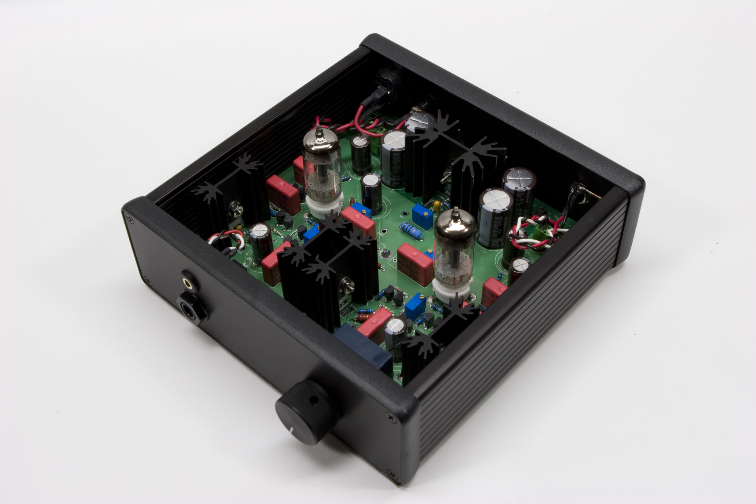 Almost-complete… Just needs the top panel fitted.
Two things accomplished tonight… For one, the Millett Hybrid Max headphone amp I’ve been working on seems to be working consistently. I still have to get the top cover fitted and make some custom cables, but that will all come after I’m certain the bias is stable.
As of right now I’ve got it running at 27VDC with each tube biased to 13.5VDC. The bias for the MOSFETs is as close as I can get to 200mV, and it’s all sounding good. I had it hooked to my crappy Yamaha player earlier and it was sounding good, but when I hooked it back up to the Playstation (as seen last night) I couldn’t get the PSX to read discs any more. I think the laser on it has gone, just like they did in so many others.
I’ve only owned it a week, but I sort of expected this. I’ll try and pick up a new transport and at the same time do some work on the audio out circuit. I may even hack up a controller so I can have Play/Pause, Stop, Next, and Previous buttons located on the top of the case.
Tomorrow I’m also going to try and get things set up so I can listen to chiptunes from a MIDIbox SID-NUXX on it.
Oh, and a few more of the decent inside photos showing the wiring for the various connectors and top panel and such can be seen here (photo gallery retired), if you are interested.
1) I should be in bed and sleeping.
2) It appears that I could resolve the inrush current problem by instead throwing a thermistor in place of (or in series with) the fuse. I just need to figure out how to spec out the appropriate part. Let’s see… 24VAC, no more than 1A in…
Now? Sleep.
 Guess where this is going…
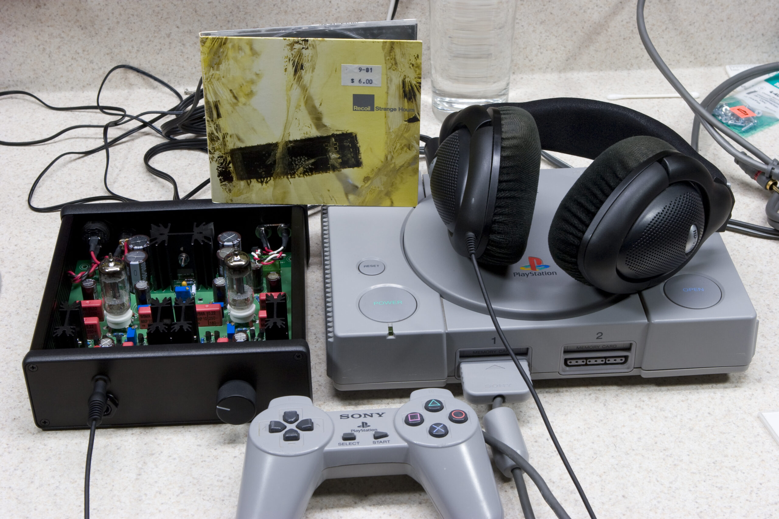
Yep, that’s the (now working) Millett Hybrid Max with recently installed 3.5mm headphone jack, connected to my Sennheiser HD570 headphones and a recently acquired SCPH-1001 Playstation. The amp isn’t set up yet, but I’ve got the problem figured out. Unfortunately I used up
Want to know what the problem was / is? In short, the designer(s) screwed up. Again. This time it’s with the power supply / fuse requirements.