A few days back I released my x0xb0x artwork into Creative Commons, but I didn’t mention what it was that got me thinking about the artwork and its license, prompting me to do this. It turns out that James Irwin was wanting to print more copies of this artwork up to sell via his shop AbleIdeas. Wanting the art available for others I licensed the art as I did, giving him permission to print and sell copies, and he agreed to send me one piece.
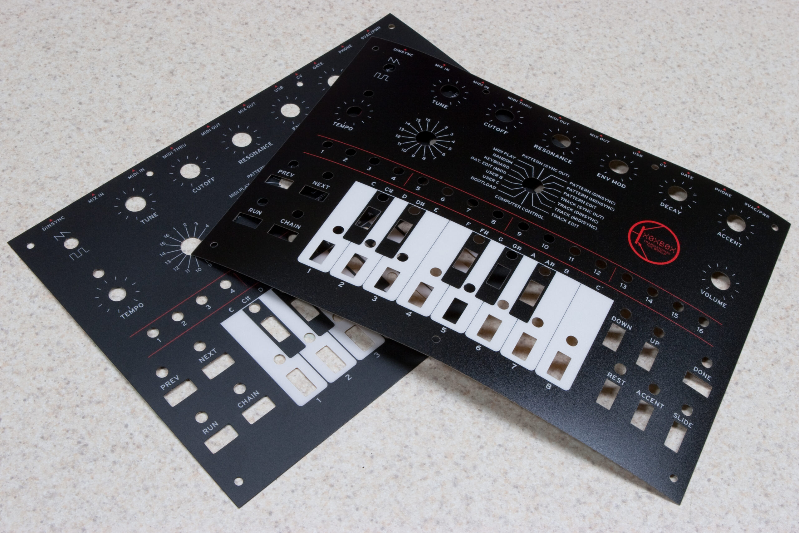
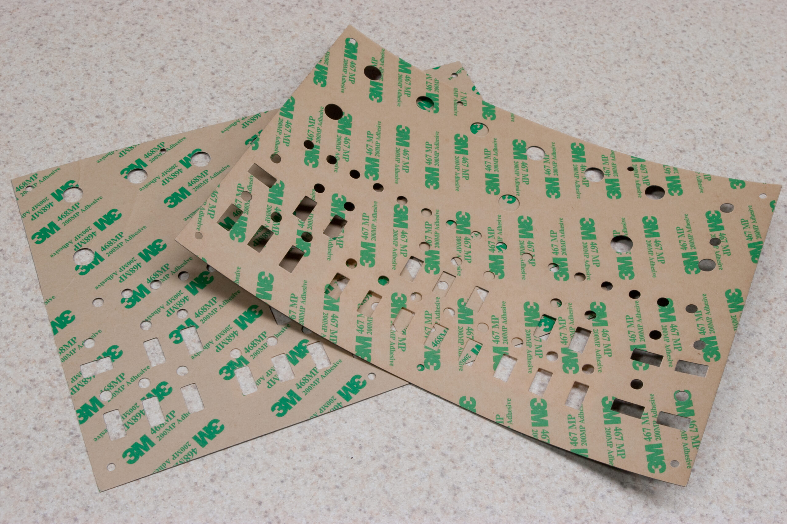
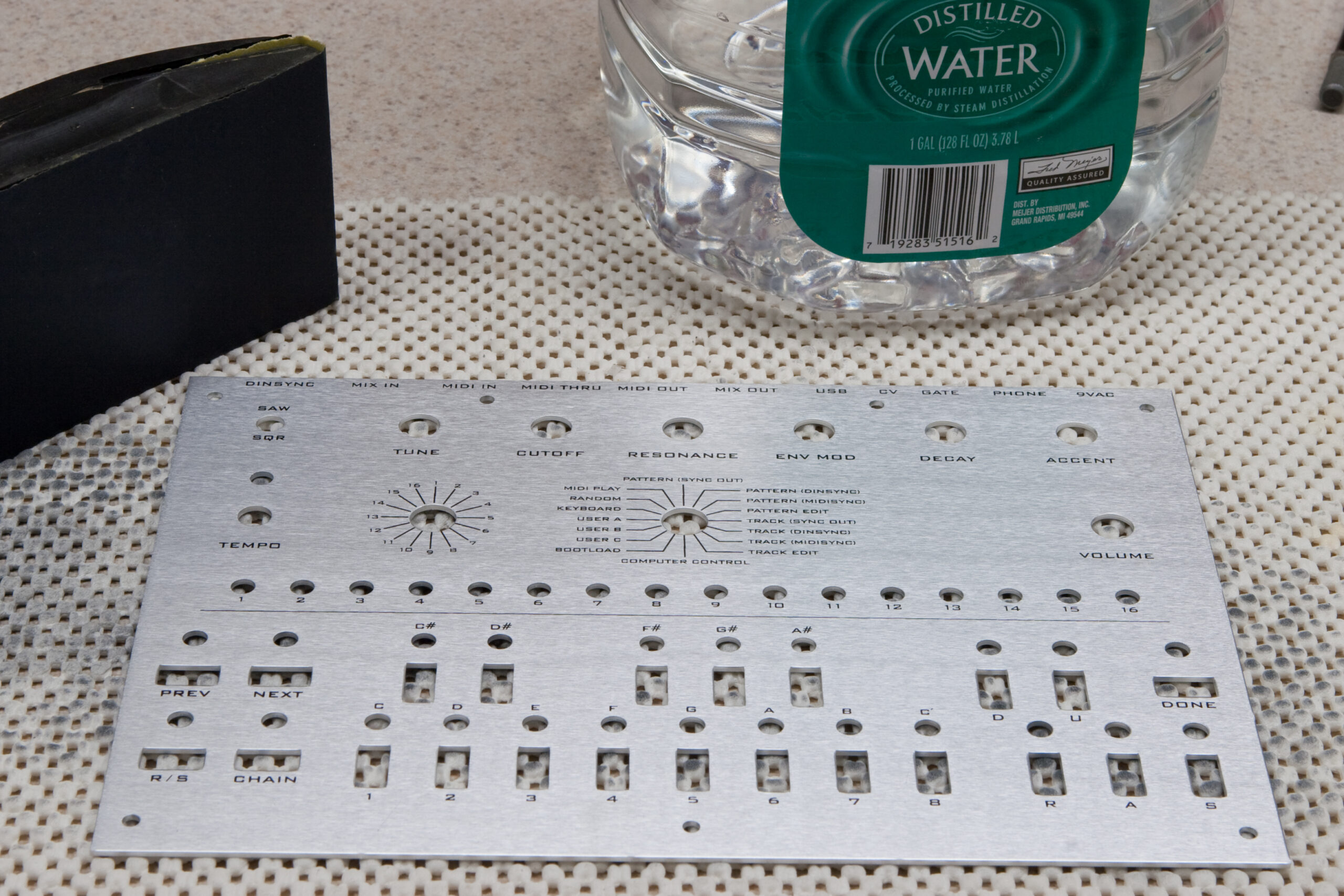
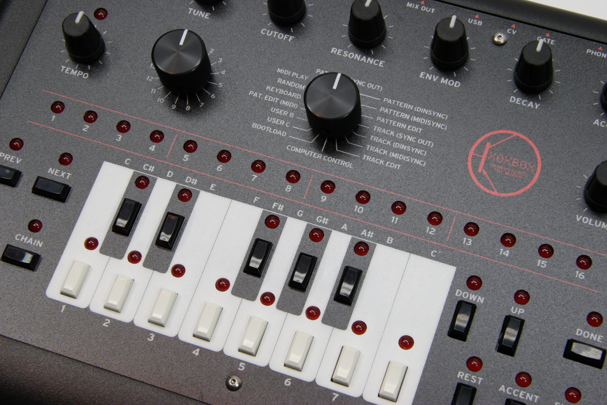
I received this piece of x0xb0x art today, and I must say that it looks pretty good. The texture of the plastic on the top layer is a bit more matte than my original pieces from Maverick Label, but the print quality and the cutting looks great. Lining one of his pieces up with mine showed them to be practically identical. The adhesive backing is the slightly thicker 3M 468 MP, which is 5 mil as opposed to the 2 mil 467 MP I’d selected from Maverick. This will adhere better to rough surfaces, but supposedly doesn’t help with the bond on smooth surfaces. I’ve been told that this adhesive will change to the 467 MP in future runs.
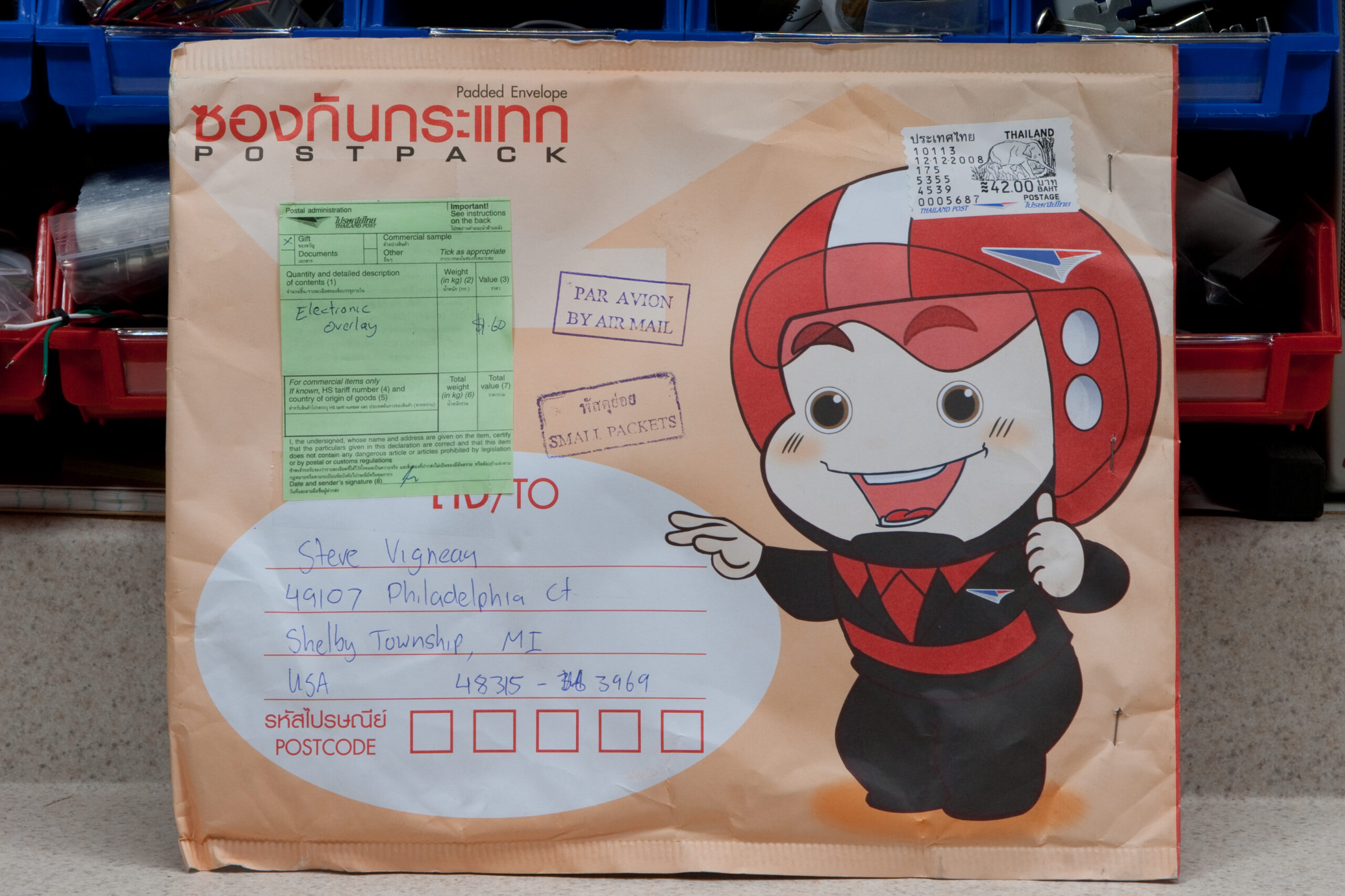
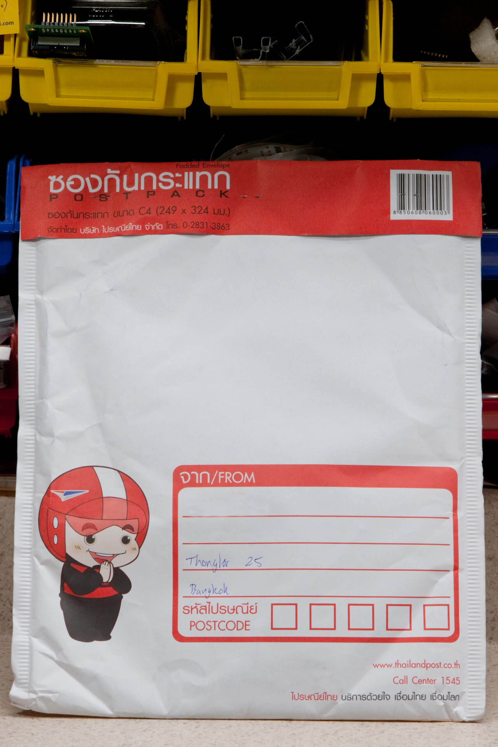
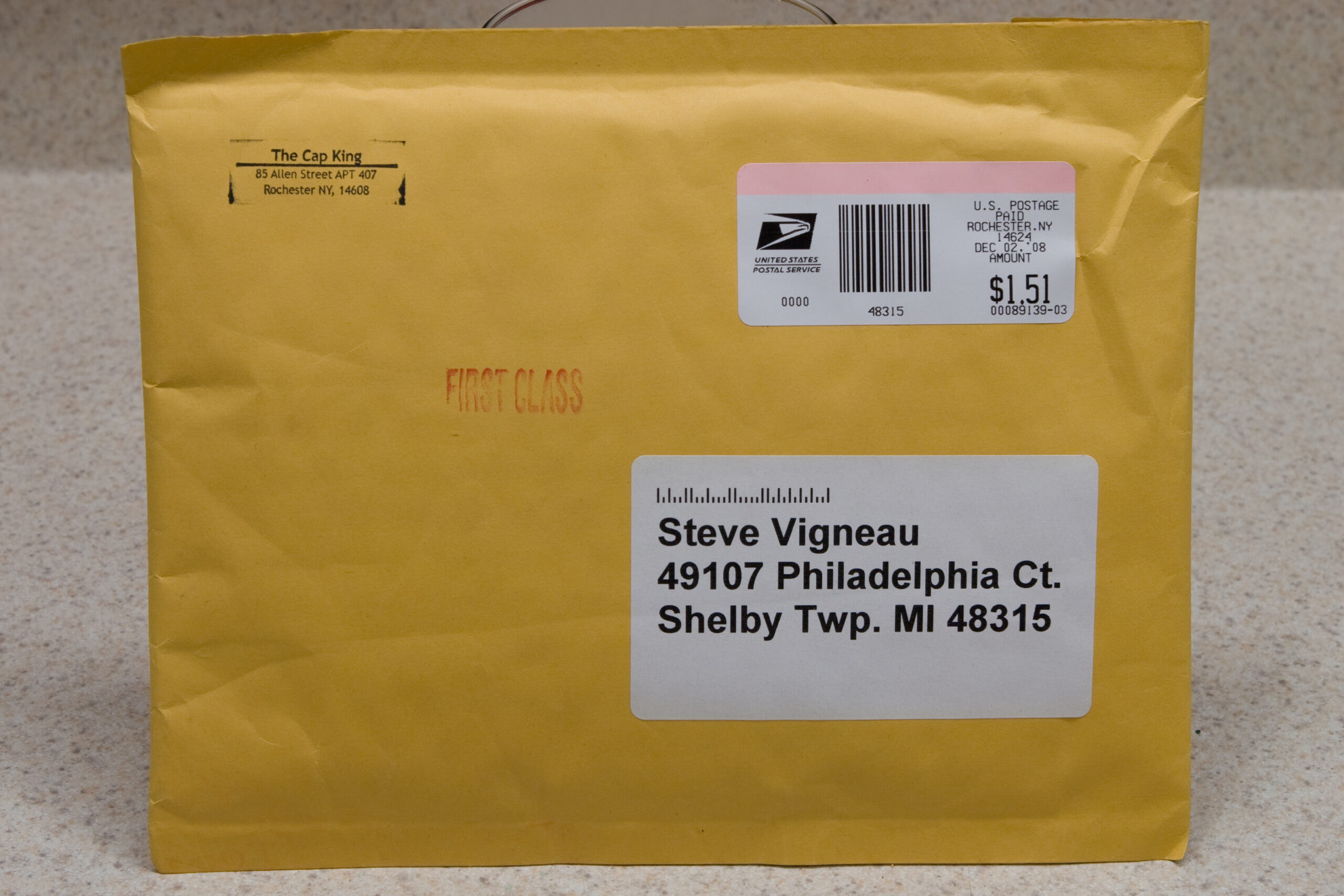
Oh, and (possibly) best of all? The Thailand Post (ไปรษณีย์ไทย) envelope the artwork came in was exceedingly cute (front · back). It could have used some backing board to ensure the artwork didn’t get bent (as the slight wrinkles visible here on the backing paper allude to), but the plastic looked just fine. I’ve mentioned this to James and he’s made note of it.
So, if you’re wanting some of my artwork printed up for your x0xb0x and don’t want to order in quantity from Maverick Label, definitely check out AbleIdeas x0xb0x store.
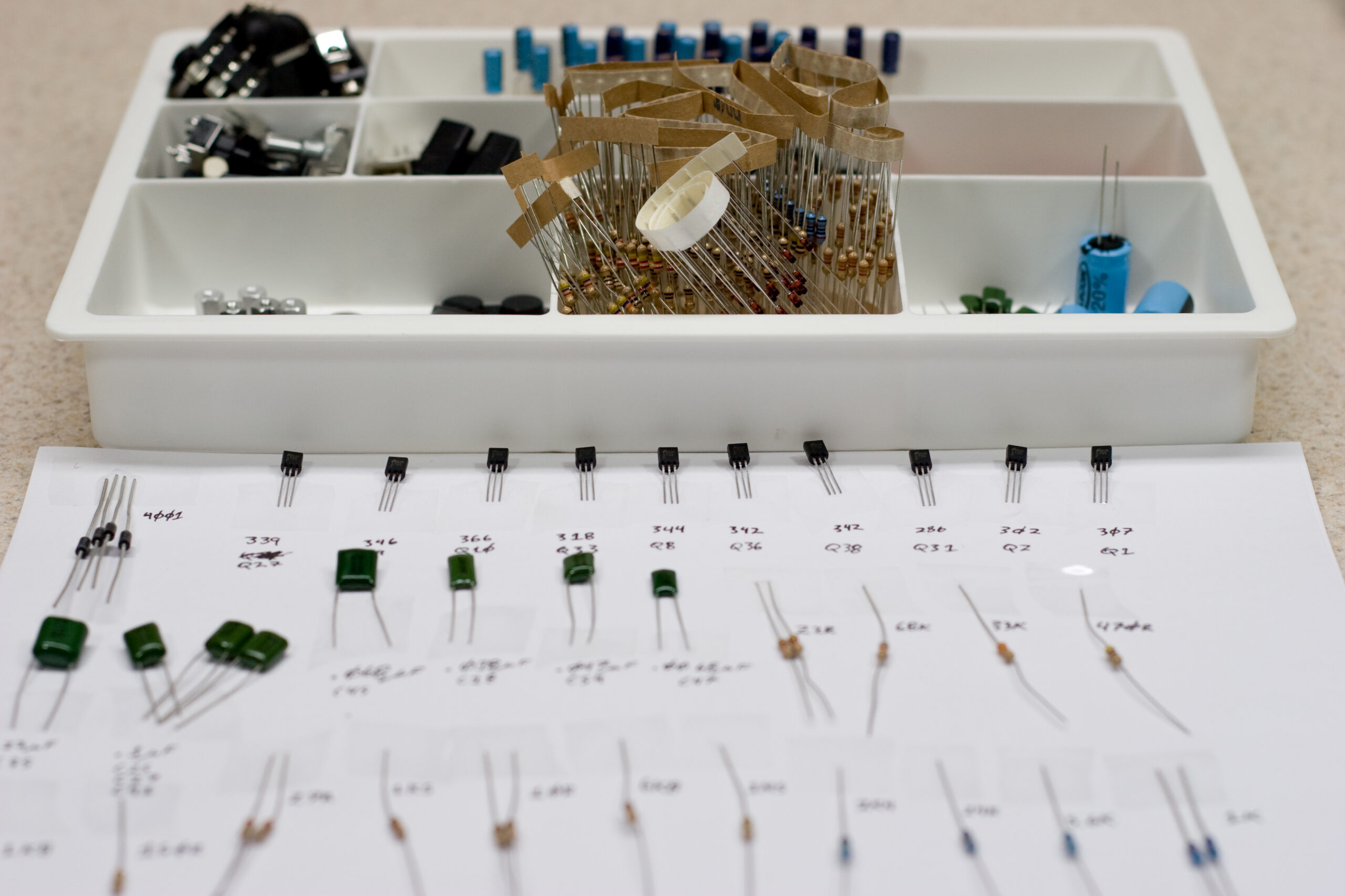
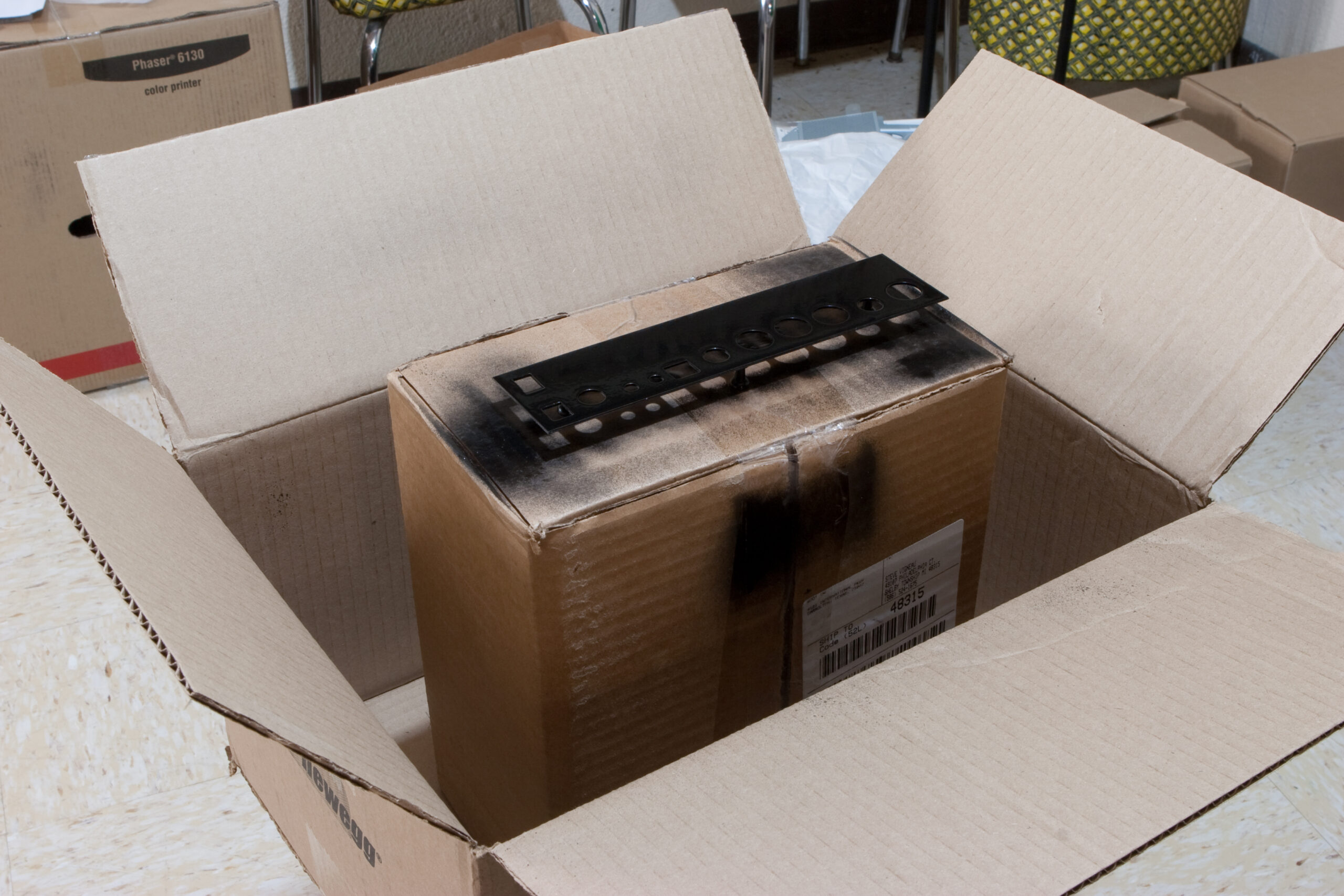
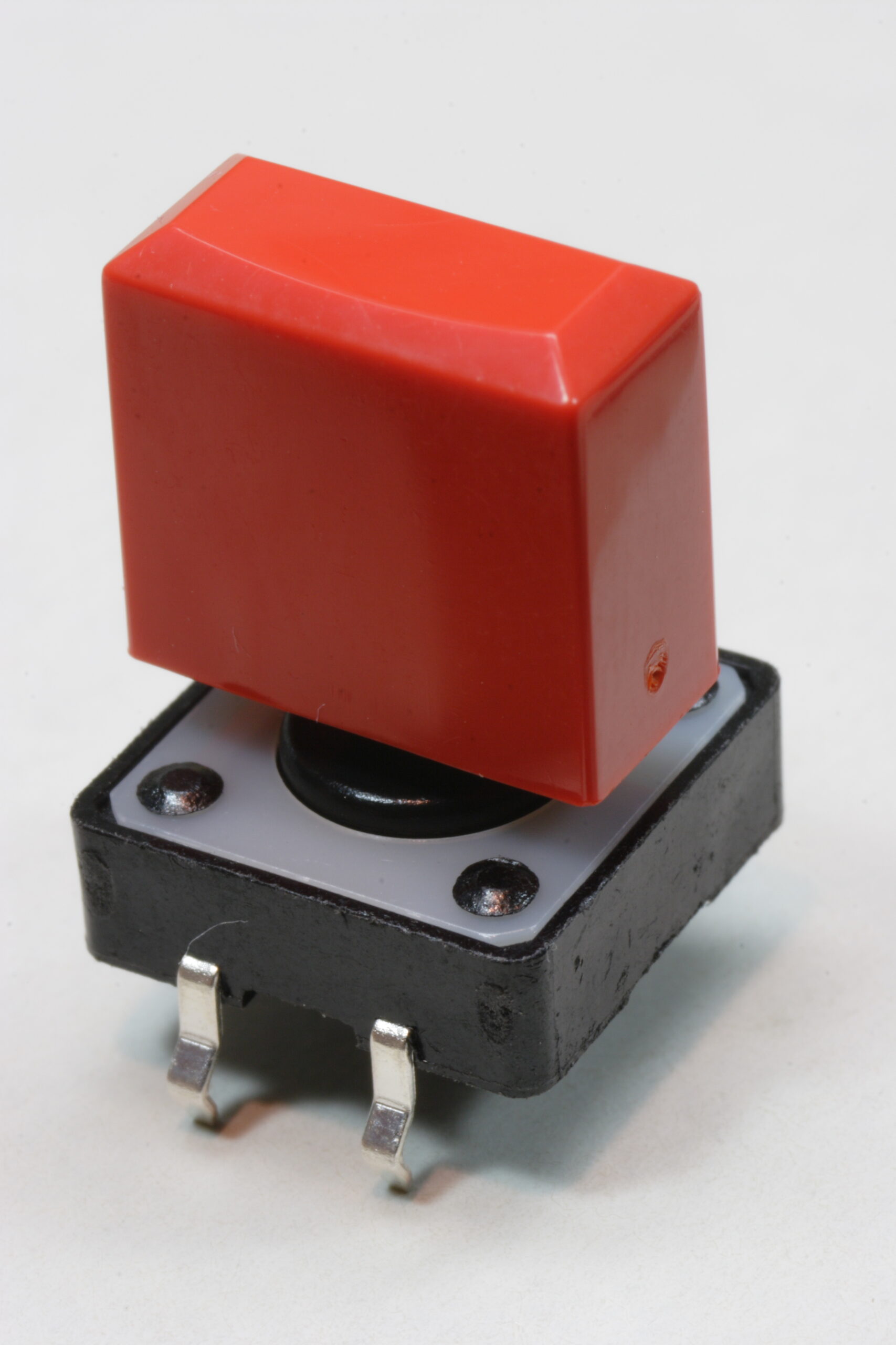
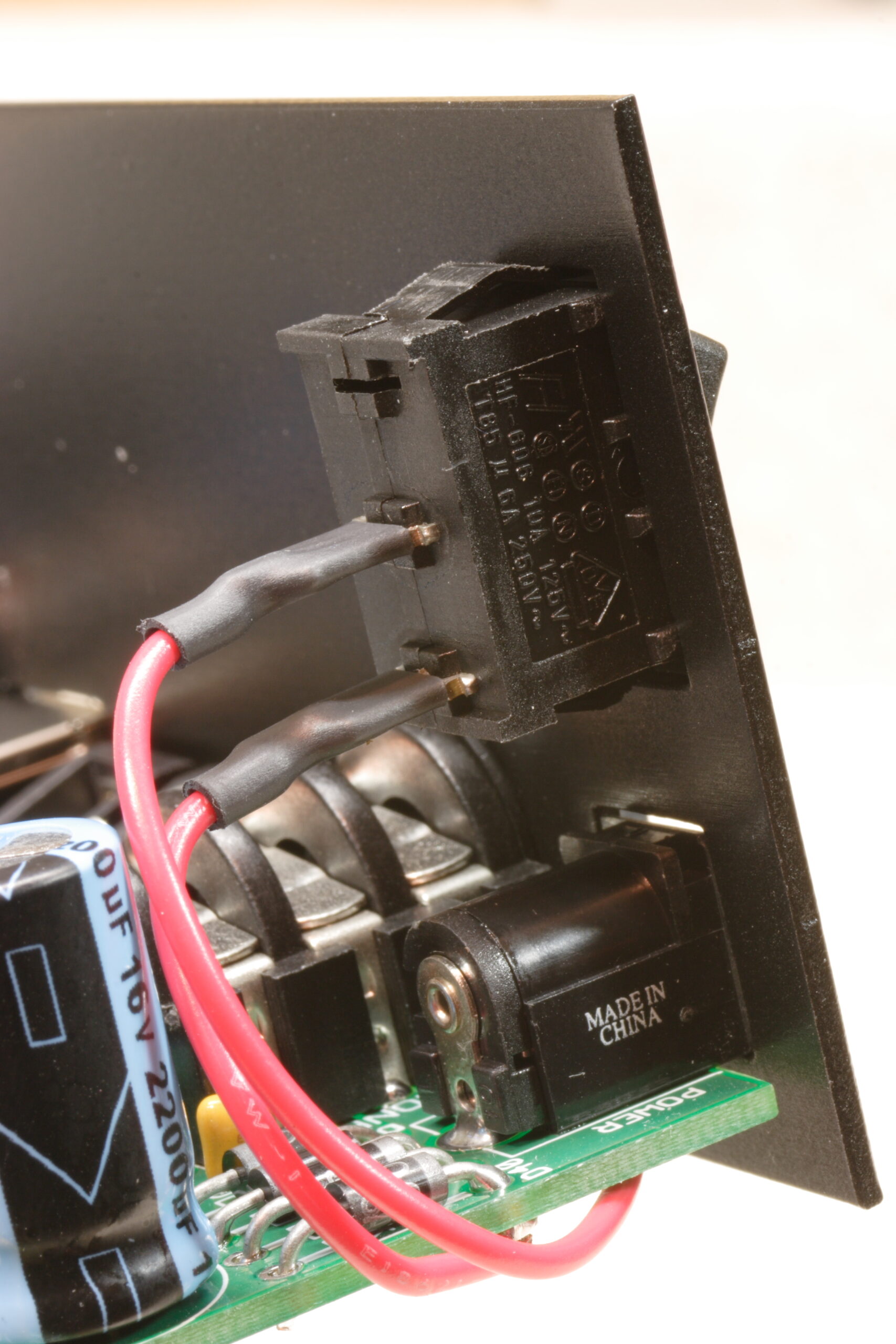
In x0xb0x #888 building news, tonight I sanded down the front panel to remove the epoxy lettering, cut a hole in the rear panel for the power switch, fashioned an impromptu indoor painting area, then began painting the rear panel. Hopefully I’m only a few days away from applying this artwork and finishing off another x0xb0x. I do still have to order some knobs and pushbuttons from Digi-Key, but those are essentially only finishing touches. Those can be changed after the case is closed.
