While I don’t normally have a problem with eBay auctions, I’ve just had the first transaction which may turn into an issue.
In this auction, #8796103506 I won a C64 and spare motherboard. The auction lists the items as follows:
Hello and welcome to my auction!
What I have here is a Commodore 64 unit with a spare motherboard for parts / chips. It's in great shape but I no longer have the power supply for this unit...therefore I was unable to test it before I put it up for auction. I remember it working when put in storage years ago but as with anything recently untested of this age..it is...yep you guessed it...as is.
I'm thinking that this would be a great chance to grab some sid, vic, or ram chips for your next project. I just need to clear everything out of my house! If you can give these units a good home this please feel free to bid!
Thank you, take care, and good luck!
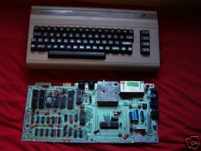
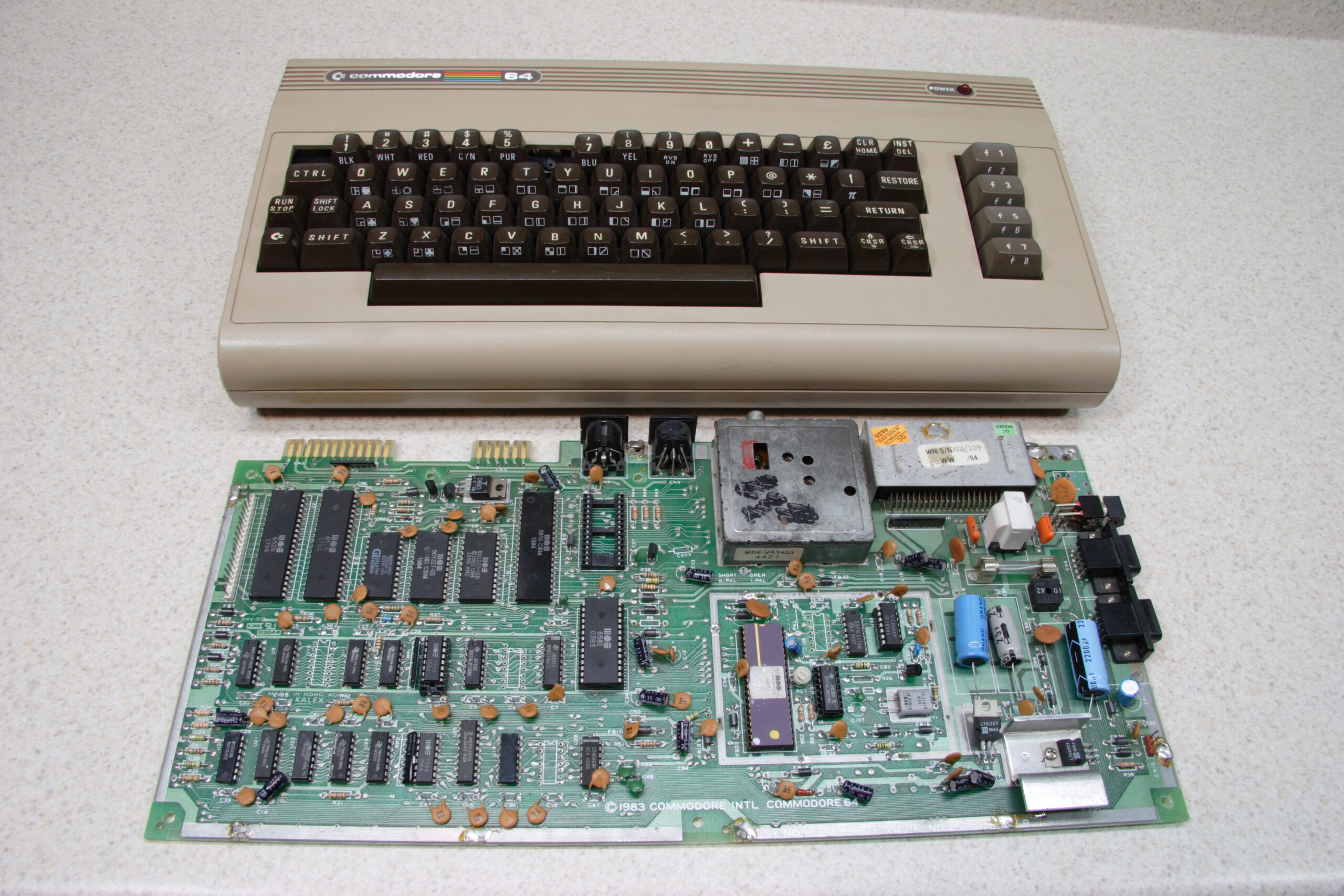
The description doesn’t sound too bad, and with the photo (mirrored here) showing an intact C64 and a board with all chip locations populated, I figured it would be a reasonable place to look for a few SIDs.
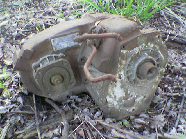
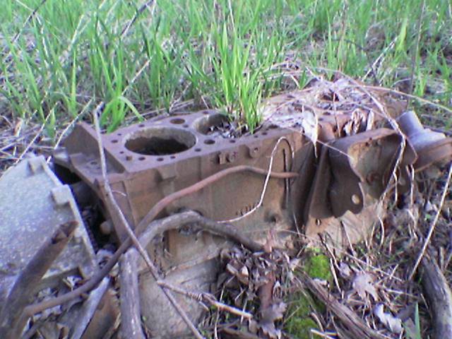
Well, what I ended up receiving is what you see above. The C64 is missing keycaps, the motherboard is missing parts, and its layout doesn’t even match the one shown in the auction. I can understand untested, but wholly misrepresented? I’d rather not go through the whole process of reporting the person to eBay and PayPal and whatever else is involved in handling this. < sigh >
I’ve sent the person the following message, so we’ll see what becomes of it all:
Tyler,
I received the C64 and spare motherboard today. Thanks for
getting those out so quickly. Everything was also very nicely
packed. However, there is a bit of a problem with the items I
received. The items I received don't match the photo nor
description in the auction.
First, the 'spare motherboard' doesn't match the photos, and is
missing parts which are clearly shown in the photos.
Second, the 'whole' C64 is missing keys which are shown in the
photo, and parts have been removed from the inside of it.
Most notably the CPU and SID.
While I understand that the auction was for untested parts, the
parts I received are clearly different from those described and
pictured in the auction.
I have photos of the items I received today available for you as
proof if you wish to review them.
Please contact me as soon as possible about this, as I'd like to
get everything sorted out as easily as we can manage.
Thank you,
-Steve
Sure, it was only $18 or so, but I could really use the parts there. Reading into what I’ve found on him thus far on Google, he seems to be a bit of a musician. I’m wondering if he bought some C64s for SIDs, parted them out, and is trying to dump them on eBay with false photos and misleading descriptions. I’m hoping that he just was running multiple auctions and send me the wrong parts. But hopefully he can correct the problem.
We’ll see.