nuxx.net
Making, baking, and (un-)breaking things in Southeast Michigan.

eBay Wins Again!

While I don’t normally have a problem with eBay auctions, I’ve just had the first transaction which may turn into an issue.

In this auction, #8796103506 I won a C64 and spare motherboard. The auction lists the items as follows:

Hello and welcome to my auction!

What I have here is a Commodore 64 unit with a spare motherboard for parts / chips. It's in great shape but I no longer have the power supply for this unit...therefore I was unable to test it before I put it up for auction. I remember it working when put in storage years ago but as with anything recently untested of this age..it is...yep you guessed it...as is.

I'm thinking that this would be a great chance to grab some sid, vic, or ram chips for your next project. I just need to clear everything out of my house! If you can give these units a good home this please feel free to bid!

Thank you, take care, and good luck!

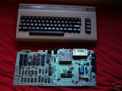
The description doesn’t sound too bad, and with the photo (mirrored here) showing an intact C64 and a board with all chip locations populated, I figured it would be a reasonable place to look for a few SIDs.

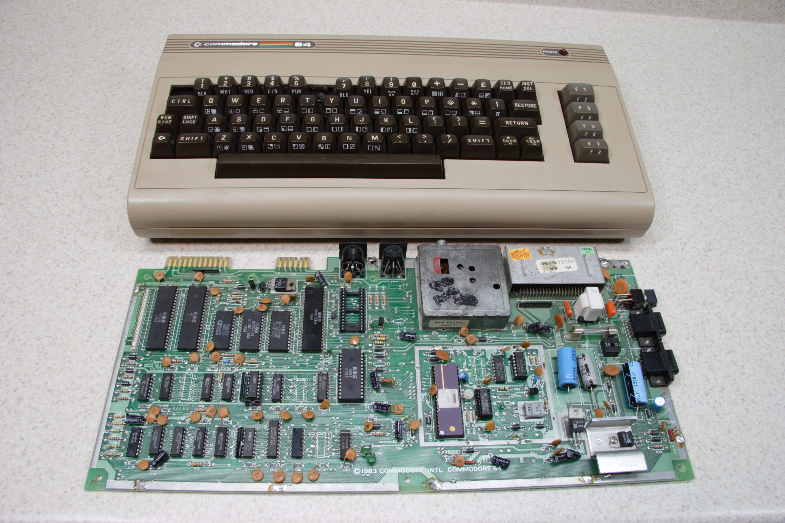
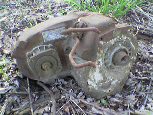
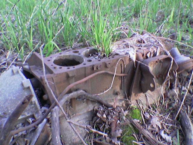
Well, what I ended up receiving is what you see above. The C64 is missing keycaps, the motherboard is missing parts, and its layout doesn’t even match the one shown in the auction. I can understand untested, but wholly misrepresented? I’d rather not go through the whole process of reporting the person to eBay and PayPal and whatever else is involved in handling this. < sigh >

I’ve sent the person the following message, so we’ll see what becomes of it all:

Tyler,

I received the C64 and spare motherboard today. Thanks for
getting those out so quickly. Everything was also very nicely
packed. However, there is a bit of a problem with the items I
received. The items I received don't match the photo nor
description in the auction.

First, the 'spare motherboard' doesn't match the photos, and is
missing parts which are clearly shown in the photos.

Second, the 'whole' C64 is missing keys which are shown in the
photo, and parts have been removed from the inside of it.
Most notably the CPU and SID.

While I understand that the auction was for untested parts, the
parts I received are clearly different from those described and
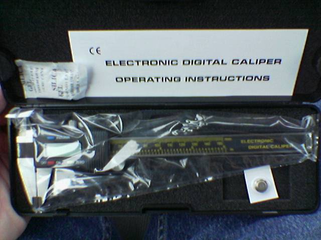
pictured in the auction.

I have photos of the items I received today available for you as
proof if you wish to review them.

Please contact me as soon as possible about this, as I'd like to
get everything sorted out as easily as we can manage.

Thank you,

-Steve

Sure, it was only $18 or so, but I could really use the parts there. Reading into what I’ve found on him thus far on Google, he seems to be a bit of a musician. I’m wondering if he bought some C64s for SIDs, parted them out, and is trying to dump them on eBay with false photos and misleading descriptions. I’m hoping that he just was running multiple auctions and send me the wrong parts. But hopefully he can correct the problem.

We’ll see.

acquired thingscomputersmoved from livejournal

PICs, SIDbox, and Mistakes


Microchip PICkit2 to DIP40 Adapter

Okay, so this post is going to contain lots of babbeling as I try to get my thoughts together…

First off, it seems that I made a bit of a mistake with this SIDbox I’m working on. The mistake stems from my thinking that the PIC18F452 is part of the PIC18F4520 and can thereby be programmed with the PICkit2 which I have. I was wrong.

Based on this faulty thinking, I both built the PICkit2 to DIP40 adapter (photo gallery retired) which you can see above and included support for using this programmer in the SIDbox (photo gallery retired) I hope to build.

So now I’ve got some hardware / connectors on the SIDbox PCB which are pretty much useless as the device would normally work.

At this point I have two choices…

The first is to build a new PIC programmer (probably connected to a serial port) which will properly flash the PIC18F452 using the 1×6 pin header found on the DIP40 adapter (photo gallery retired) and the SIDbox (photo gallery retired) and use the existing hardware layout and order the PCBs.

The second option is to use a newer PIC, the PIC18F4620, on the SIDbox instead. This has the advantage of being completely compatible with my programmer and thusly the adapter and the programming hardware on the SIDbox board. However, there appears to be a bug in the hardware of the PIC18F4620. The end result of this bug is that one can’t use a MIDI output directly from the chip. So, I’ll have to add some additional hardware to provide MIDI output. On the upside, this extra hardware (the MIDIbox IIC MIDI module) provides for MIDI LEDs, making part of my existing design redundant. That means some board space is freed up for the new hardware.

So, at this point I’m not completely certain what to do, but based on the responses I am getting to this post at the MIDIbox forums, I think the second option is going to be the best one. In fact, I’m going to change the schematic and start laying out the board for this now. Just in case I decide that’s the best way to go.

electronicsmaking thingsmoved from livejournal

SIDbox Update… Again…


SIDbox PCB Layout
(Click for more of the SIDbox album…)

Nope, there’s not much in the SIDbox (photo gallery retired) album yet, but I do have what I believe to be the final schematics and PCB layouts. I’m just waiting on some parts from Mouser and Digi-Key to arrive so I can confirm the desired layout, then I’ll place the order for everything.

Also, here is a post I made to the MIDIBOX.ORG Forum about the project:
Cut to save page space…

electronicsmaking thingsmoved from livejournal

Erma’s Frozen Custard, et all.


Erma’s Is Open!!!
(Click for more moblog photos…)

So, I screwed up. I thought I had a dentist appointment today, so when arriving at my dentist’s office at 5:50pm, he was there alone, most of the lights were off, and he was rather surprised to see me. We discussed what’s going on with his computers for a bit, then I headed home. Well, that was the plan, but then I ended up heading over to Holland Ponds Park to wander around.

Here’s some photos from there. The one with the flag in it would have made a better title photo, but… Yeah. Just look at them:

· A nicely twisted, mangled tree in Holland Ponds Park in Shelby Township, MI.
· A plastic American flag hanging from some dead branches, found along the bank of the Clinton River in Holland Ponds Park.
· Another portion o the previously pictured engine which I came across in Holland Ponds Park.
· An engine block I came across in Holland Ponds Park.
· A nesting Canadian Goose setting on top of a fallen tree in the middle of the Clinton River in Holland Ponds park.

After that, I decided to use the last $2 in my wallet to head over to Erma’s Frozen Custard in Utica for some classic southeast Michigan frozen custard. Mmm. Erma’s being open means that springtime has definitely arrived.

And yes, that’s where this icon is from.

Now, I’m home. Just simply home. There are sheets in the laundry, the precipitate from disposing of the ferric chloride is drying in the garage, I’m making some final tweaks to my SIDbox’s board layout, and there is another bottle of Dark Horse’s Double Crooked Tree IPA chilling in the fridge, waiting for me to drink it later.

I use ferric chloride to etch PCBs. Well, the solution I have was becoming a bit weak, so I decided to dispose of it. In retrospect I could probably have used it a few more times, but… Oh well. It’s already neutralized.

In order to dispose of it, one needs to add a base (I used baking soda) until it’s pretty neutral, then it is let set in order to separate. The liquid can be poured off the top, and the precipitate can be thrown out. Unfortunately the precipitate stains with ridiculous vigor, so my laundry tub now has some brownish orange stains in it. Ah well.

In a few days I should be able to safely toss the containers of dry chemical, then head to the dollar store and get a few more. I’ll also have to source some more PCB etchant. That’ll be harder to find…

foodmoved from livejournaloutdoors

…to avoid mad display…


Harbor Freight Digital Caliper

I feel embarrassed. I bought a digital caliper from Harbor Freight Tools. It was $15.99, and it passed tests like zeroing it, QUICKLY sliding it half-way opening it, reading the measurement, zeroing it again, then snapping it shut. And it still read the inverse of the other reading. It also does metric and standard, and appears… Not bad. At least not for a $16 caliper.

There are some engrish gems in the ‘operating instructions’, though. For example, “Clean caliper bar with dry cotton fabrics before using to avoid mad display…” or “Never apply any electric pressure on any part of the caliper and never use an electric pen for fear of damaging its chip.”

The original reason I went there was to get some slatwall-type plastic sorting bins to put electronic parts into. I managed to get what I wanted. A small metal stand with 15 plastic bins, for US$20. A bit high, but not too bad.

Time to go clean up my work bench area.

acquired thingsmaking thingsmoved from livejournal

SIDbox Update

Well… I just ordered about $150 worth of components for the SIDbox project. This is everything needed to build the first prototype except etched end panels, the PCBs, and the power supply. I’m waiting to order the PCBs until I can confirm the switches work as expect. The power supply is somewhat dependent on the type of SID installed in it. And the etched end panels… Well… They are just a finishing item, so those will wait until I’m certain that this thing actually works.

Also, I’m nailing down some final things on the PCB layout. Just… Tweaks and stuff.

electronicsmaking thingsmoved from livejournal

SIDbox PCB


SIDbox PCB (Click for 300dpi)

Yep, there it is. The first draft of the PCB for the SIDbox thingy I want to make. I need to do a good bit of checking to be sure I’m happy with it, but if I am, I’ll likely be ordering 5 of them. Then the Mouser parts order will be placed… Then (hopefully) I’ll put it together and it’ll work. I hope.

For now, though, I’m going home. On the way home I’ll stop to get something tasty (and fairly good-for-me) for dinner. Maybe tonight I’ll have a good beer, too. I’ve done enough electronics work for one evening.

Oh, and there is a copy of the Boondock Saints waiting for me to watch. Yes, I’ve never seen it.

UPDATE: Whoops, I just realized something that’s wrong with this… My hope is to solder on just the socket and pin header, then program the chip using my PICkit2 programmer. Well, without a line running from JP1P2 to VDD on IC1 (the PIC) I won’t be able to do it. Must change that…

Also:

· Rename all parts appropriately.
· Clean up BOM with new part names.
· Move JP1P1 indicator arrow to other side to align with the PICkit2’s indicator. Done.
· Establish values for the resistors for the LEDs.
· Also, maybe fix how the LEDs are connected. Currently the polarity for PWR_LED is different than MIDI_IN_LED and MIDI_OUT_LED. Maybe fix this. Probably should if kits may be sold. Done.
· Connect JP1P2 to VDD on IC1 so IC1 can be programmed with only JP1 and itself installed. Done.

electronicsmaking thingsmoved from livejournal


Click for full res…

Hmm, I think I’m done with the SIDbox schematic. Also, all the parts have packages matching the BOM I’ve been making up. I also replaced the standard MIDIbox programming header with one that matches the Microchip PICkit2.

Uhm… That’s all. I think it’s time to start laying out the PCB. I’ll probably do that tonight or tomorrow.

electronicsmaking thingsmoved from livejournal

SIDbox

Over the past couple days I’ve been attempting to learn to use CadSoft EAGLE better. I think I’ve come pretty far on it, and I’ve started working on a project that I’ve been wanting to tackle. That is, building a stand-alone SID module. Think of something about the size of an external hard drive, with MIDI IN / THRU / OUT jacks, and a pair of 1/4″ jacks for audio in and out.

Well, I think I’ve gotten pretty far on it. If any of you are interested in seeing the schematic as it stands right now, please take a look here: SIDbox Schematic

Also, if any of you who are a bit more electrically inclined could take a look at the power supply, that’d be really great. I’m not sure it’s right… I think so, but I’m not certain.

For what it’s worth, I’m hoping to feed PWR_TIP and PWR_RING 15VAC from a wall wart.

If the SID is a 8580 (the newer version) instead of a 6581, then I’ll replace the 7812 with a 7809 (since it only needs 9 VDC) and replace a few of the caps in the SID portion.

electronicsmaking thingsmoved from livejournal