nuxx.net
Making, baking, and (un-)breaking things in Southeast Michigan.

Worky worky worky…

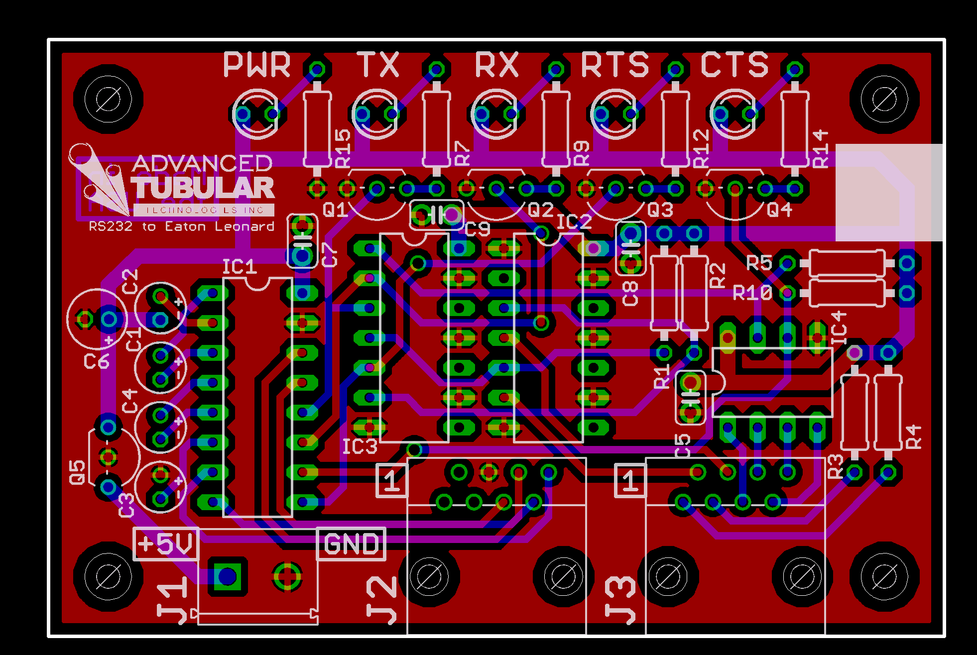
After feeling kinda crappy about my current project last night I ended up going to bed and laying there for a while thinking about things. As a result of talking to a friend online about some electronics stuffs, I decided this is what I need to do:

Breadboard the whole damn thing, so that changes and new features are easy to implement, and I can work around the inverted data problem more easily. It really is the “proper” way, as opposed to what I did before: come up with what I think should work and spend time hand-etching a PCB.

So, today I went ahead and ordered a batch of new parts, including some I’ll need for assembling the final boards, some I want to try (different FETs, dual optoisolator) instead of the current design, and a few other things. When the parts arrive I’ll breadboard it all, get it working, ensure that my schematic matches, then order the prototype boards.

That same friend also helped me out a bit with the use of FETs for current reversal protection, triggering LEDs, and a few other things. That was really, really helpful.

Advanced Circuits credits one back the price of bare-bones prototype PCBs (no soldermask or silkscreen) when production boards are ordered, so this should work out well. I also won’t have to deal with etching a board by hand.

electronicsmaking thingsmoved from livejournal

Making Stuff

I’m feeling amazingly frustrated with the project I’m working on.

I think I know why the data coming in isn’t working, but the data going out has suddenly stopped working coming out corrupt (test is received as QsT.), and I really don’t know why.

I’m considering taking a bit of a break from it, or maybe stepping way back and taking a wholly different look at it, what it does, and how I could do it better, end to end.

The problems all seem to stem from what a hack the board itself is that I’m trying to clone. Maybe I shouldn’t try to keep approximately one half of it original.

electronicsmoved from livejournalwork

It’s coming along…

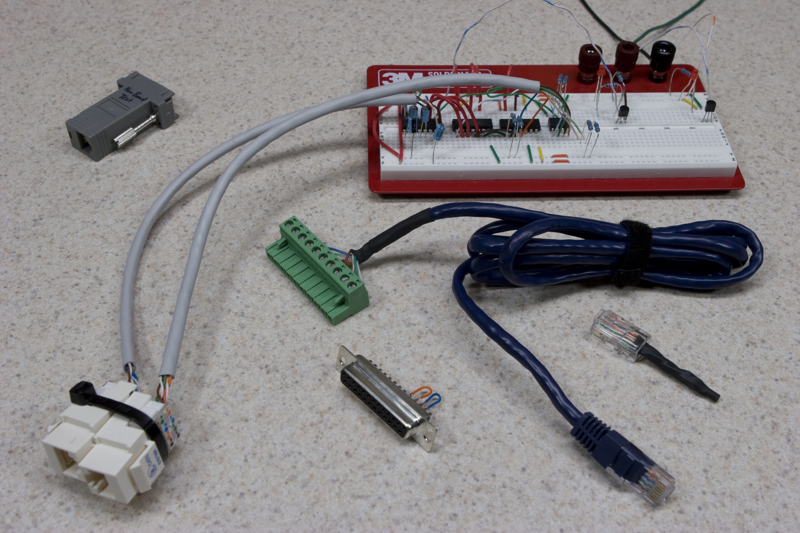
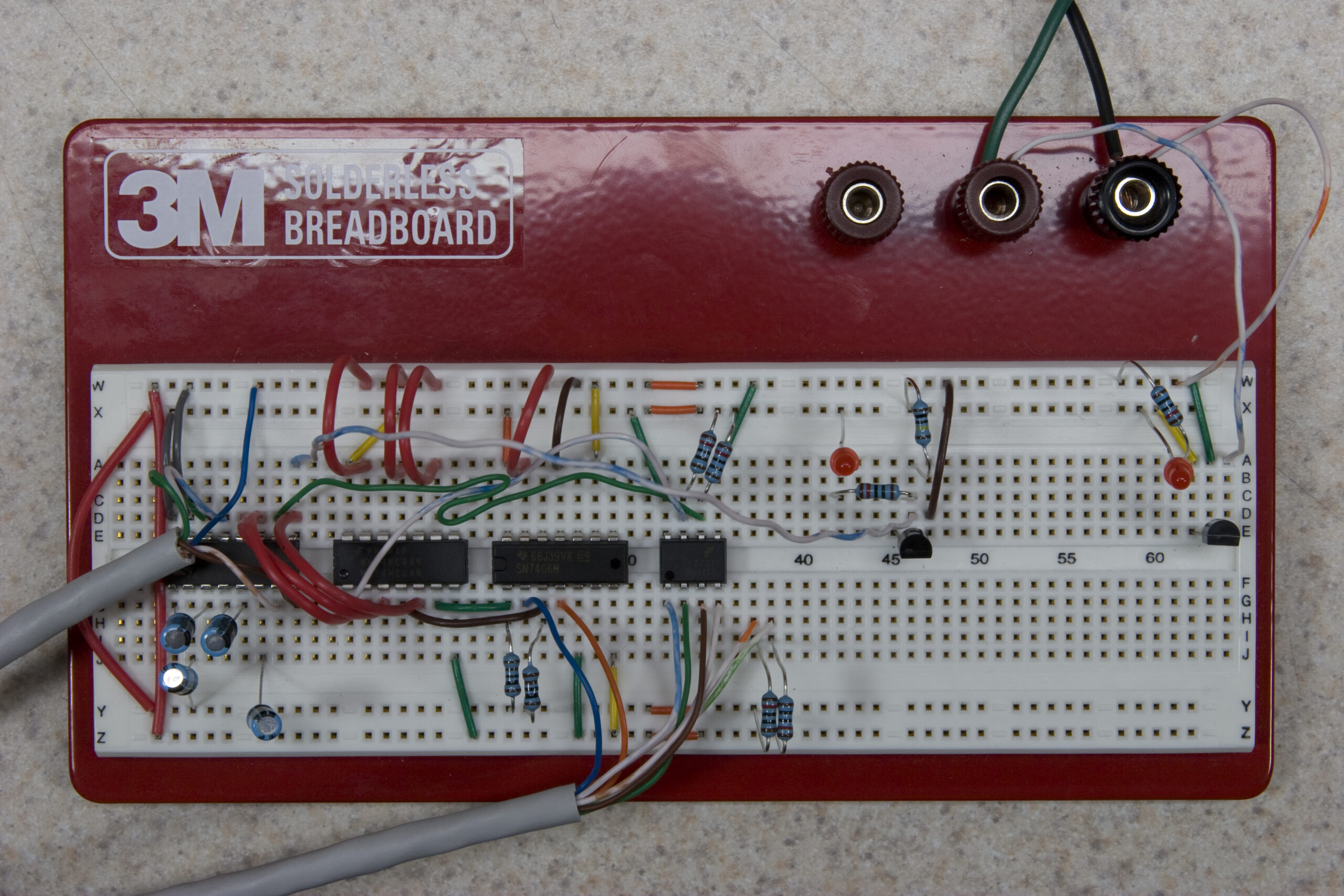
RS232 to Eaton Leonard Test Harness
(Click for full resolution image…)

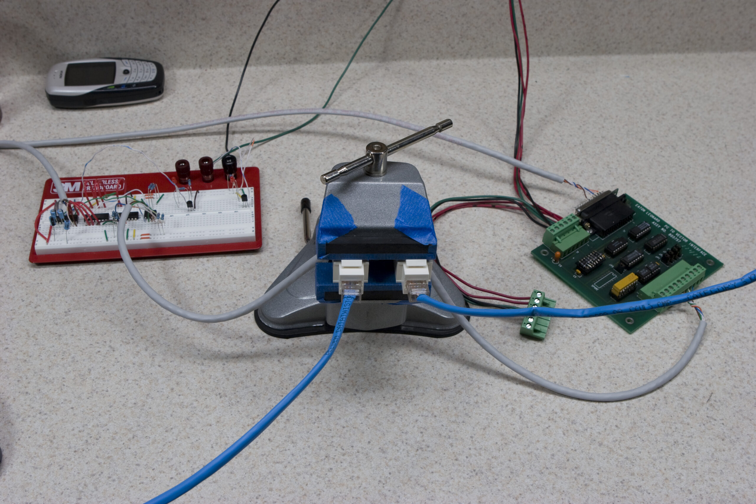
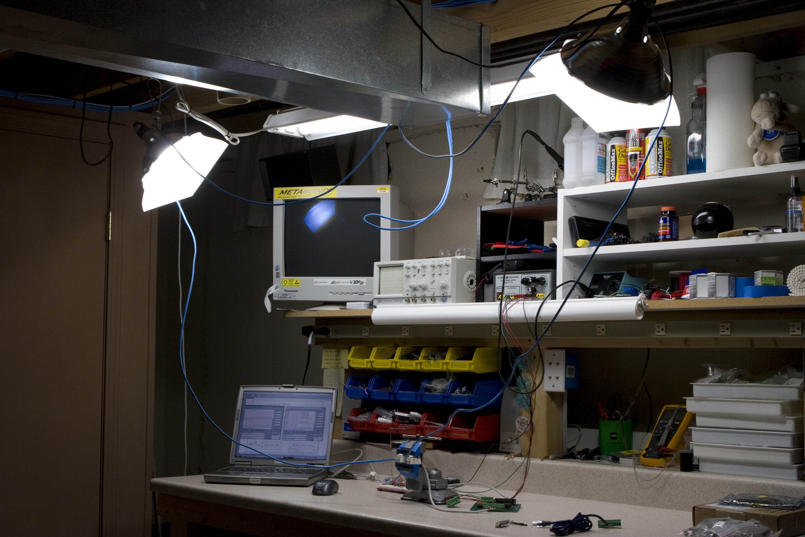
I spent a lot of time in front of this test harness tonight. Most of it was spent thinking and reading and talking with about it. And yes, because I forgot to grab some “Phoenix Connectors” from my friend’s shop, I had to hack together those power connectors seen there. And I had to be VERY careful with them. However, they work. :)

At this point I’m pretty sure I know what needs to be done to make it work. I can send data (and set RTS) out through it, so half of the circuit is working. I’m fairly certain the other half will be done soon.

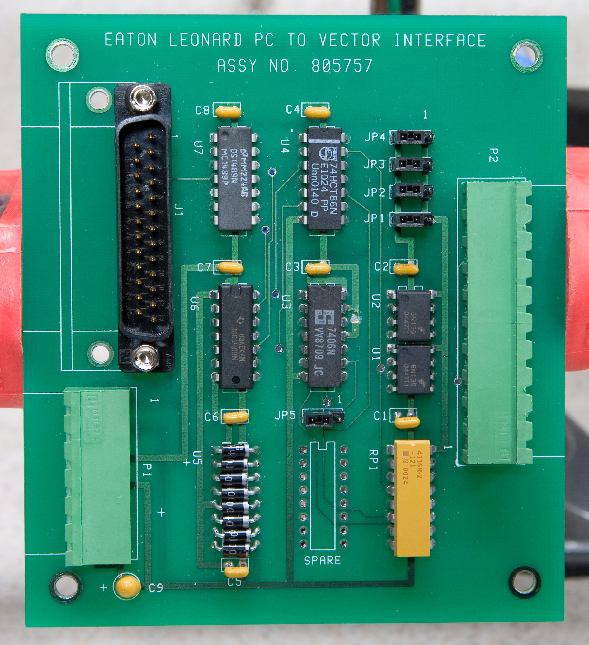
See, the old board has a MC1488/1489 pair used for RS232/TTL level conversion. It turns out that there was another two hidden traces beneath the MC1488. These traces connected the two inputs which were being used with their counterpart on the gate, causing the MC1488 to be used as both a level converter and an inverter. As the MAX232 which I replaced it with can’t invert things, I need to come up with an inverter.

There is an inverter on the CTS line, but not the RX one; the two lines which feed data to the input on the MAX232. Since there’s only one inverter, I’m pretty certain I’ll be able to do this by swapping the circuits which handle CTS and RX, and I’ll test this tomorrow.

Thankfully I was able to borrow the receiving board from inside of one of the machines today, and now I can test the product end to end, as opposed to just making it, taking it all the way to the shop and trying it, watching it fail, thinking about it, making a change, lathering, rinsing, and repeating.

Now I have no reason not to get it working on the bench, and I’m very confidant I will do so, in very short order.

I don’t think it’ll be tomorrow, as I’m heading straight to my parents house after work in order to set up my Mom’s new iMac, get the old one back from her, and other things like that.

electronicsmoved from livejournalwork

Level Shifted!

So, that RS232 to Eaton Leonard (photo gallery retired) level shifter thing I’ve been working on? Well, it wasn’t working. I took a bit of a break from it to get some other stuff done, and tonight I started back in on it. I’m fairly certain I found the problem, and hopefully that’ll be tested tomorrow.

If so, I might have my first for-pay electronics job. Yay!

(This would have been done loads sooner if I had the test environment at home, or a matching board for testing, or something. But, I didn’t, so it was a little more complicated. I don’t mean to blame anyone for this, it’s just the reality of working with one small piece of a puzzle and needing to take it to the customer’s site to test it.)

electronicsmoved from livejournalwork

x0xb0x #496

Yay! x0xb0x #496 is done. I had a bit of a problem with the MIDI In circuit, requiring me to replace R16 with a 120Ω part, because its original 100Ω part wasn’t causing the MIDI In line to the CPU to be flapped properly.

electronicsmaking thingsmoved from livejournal

Magic Skin

My skin being less resistant due to metallic enhancement.

After wet sanding the front panel of my second x0xb0x (in order to ensure that none of the original labeling bleeds through) I found that, per usual, the hand I used to keep the piece of metal from sliding around was a dull grey color. That color comes from the aluminum dust ground off the plate embedded in my skin.

Knowing that there was metal in my skin made me grab the multimeter and see if that part of my skin was more conductive than the other, less metallic hand. Well, as expected, it was. As you can see above, the first finger on my left (metalized) hand provided 1.028MΩ of resistance. The same finger on my right hand, which was also washed a few minutes prior with the same soap, gave a reading of 4.451 MΩ.

electronicsmaking thingsmoved from livejournal

Millett Hybrid MAX – Part 2

There. Another ~$150 later and I think the rest of the parts for the two Millett Hybrid MAX headphone amps have been ordered. I’m fairly certain that everything has been paid for and everything is on the way.

Yay!

(No, this doesn’t include enclosure design nor input circuitry, but that’s okay…)

electronicsmaking thingsmoved from livejournal

Millett Hybrid MAX

Well, the PCBs from the group buy, MOSFETs (IRFZ24N /IRF9Z34N complimentary pair) and high-quality pots from AMB audio shop, and 7-pin PC mount sockets from TubeDepot have been ordered.

I still have to source some appropriate tubes (probably 12AE6 or 12AE6A, likely on eBay) and place the order for the bulk of the parts from Mouser. But the difficult things have been selected. :D

Soon and I will be on our way to completing some of the Millett Hybrid MAX headphone amps with MOSFET-based output stages.

I’m thinking I’ll follow Matt’s lead and mount mine on some sort of wood platform, surrounded by a cage. I’ll probably also incorporate an iPod dock / charger so I can use it where I use headphones most; on my desk at work.

UPDATE: Five NOS GE 12FM6 tubes purchased via eBay for US$20.50 shipped. These have a slightly lower amplification factor than the 12AE6/12AE6A tubes which most people seem to use for them (13.5 – 10 vs. 16.7 – 14.3), but I don’t think this will be an issue.

Now to order the first go-round of parts from Mouser, Digi-Key, and wherever else is needed to ensure that all required parts are in stock. Oh, and an FT232BM to replace the one I stupidly cooked last night.

electronicsmaking thingsmoved from livejournal