nuxx.net
Making, baking, and (un-)breaking things in Southeast Michigan.

Category electronics

PAiA FatMan Plus Panel Idea

Up above there is the rough idea I just threw together for the front panel of the PAiA FatMan which I’m rebuilding. I am going to be putting it in a new enclosure and adding some extra stuff to it, so I need to design a new panel.

I’m curious if those of you who are familiar with using synths what you think of this… I tried to somewhat follow the original FatMan desktop enclosure layout, adding the mods (subharmonic generator and VCO hard sync) where appropriate.

No, things aren’t lined up yet, labels aren’t in there appropriate places, and there are no knob position indicators… I’m just trying to get some layout ideas. Also, the three vertical columns of controls will be sized the same and properly centered. Also, the groupings will be labeled similarly to how the VCF one is. Oh, and the whole thing will likely be in white lines and text on black, similar to the x0xb0x. It’s just easier to start designing this way.

So, what do you think? What would you change?

Thanks!

electronicsmaking thingsmoved from livejournalmusic

Elenco XP-720K


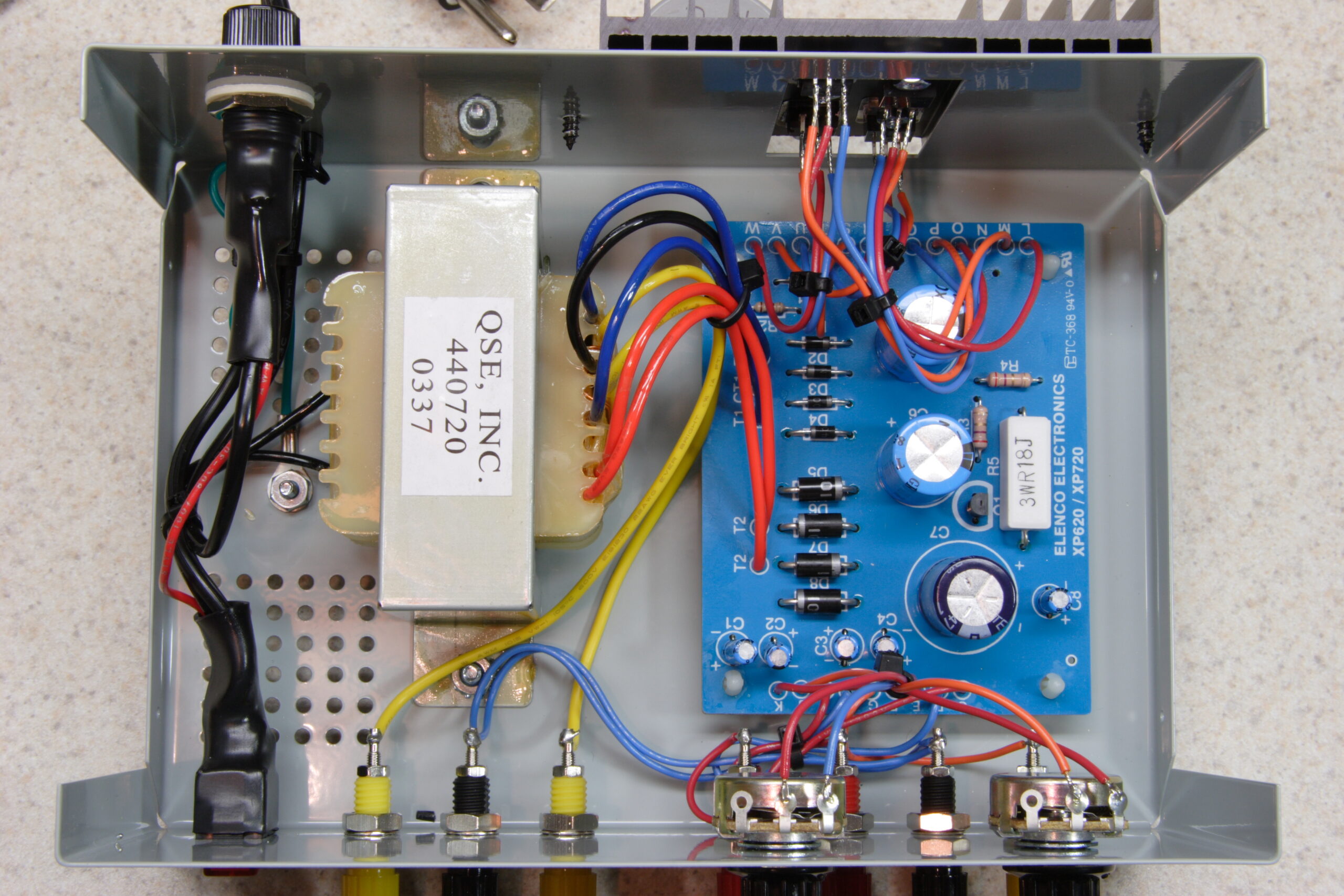
Inside of the completed Elenco XP-720K
(Click for more…)

Yesterday I received the Elenco XP-720K kit which I ordered last week from KITS USA. Their price of $44.95 for it was far cheaper than most other places, so I was able to get it with a few lead sets (banana plug to alligator clip, banana plug, and micro connector) for around US$60 shipped. Not a bad price at all for such a well made kit power supply, I don’t think.

Anyway, building it went rather well, and the biggest problem I had with it probably revolved around the detail of the manual. The problem was not with too little detail, but actually too much. It seems that this kit has its manual designed to be used in school for learning purposes, so it goes rather step by step of hooking up every part. It wasn’t a big issue to deal with, though. The nice thing about it being this sort of kit is that the function of the entire supply is clearly detailed in the back of the manual, wholly explaining how a rectifier works, what each part does in the circuit, etc.

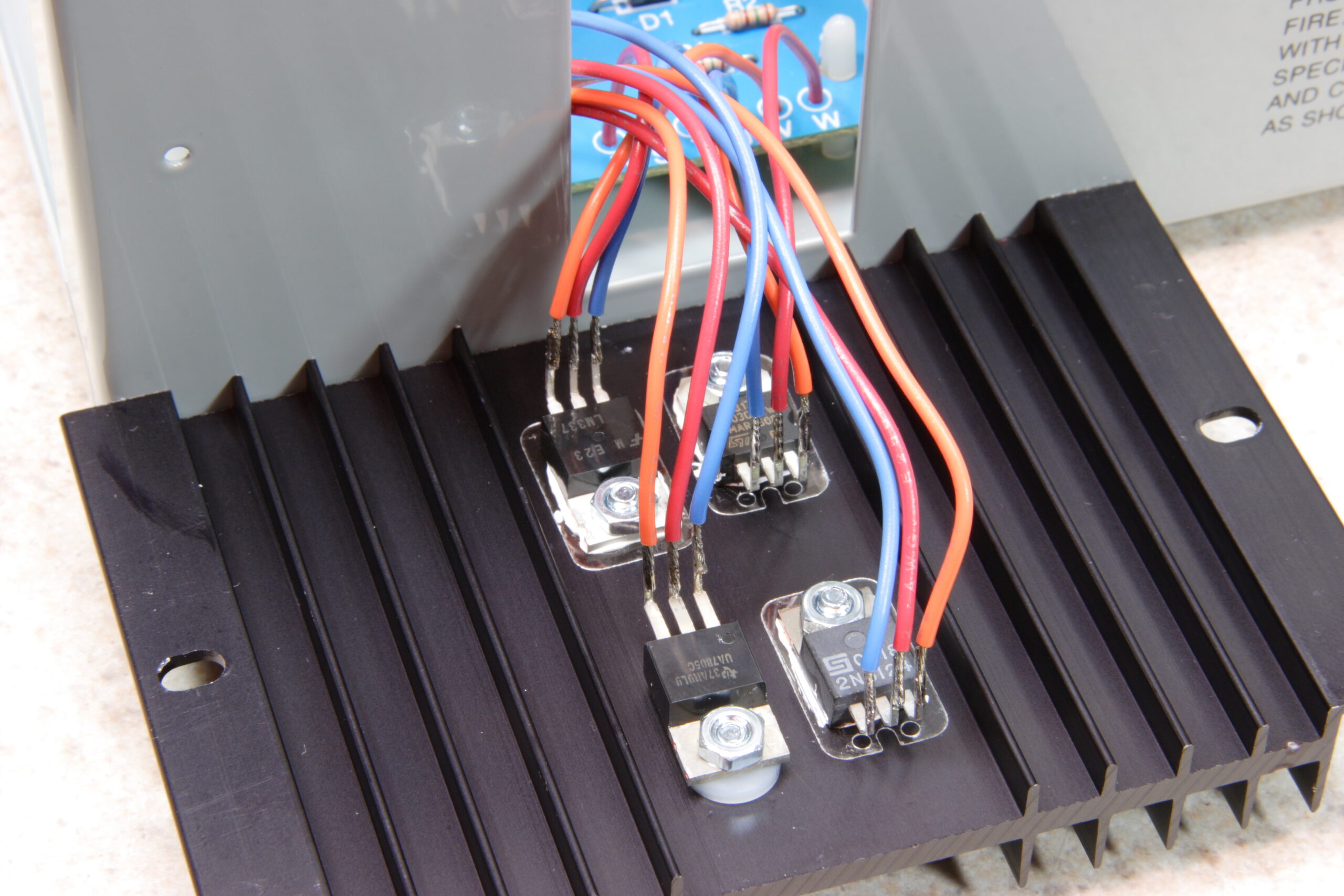
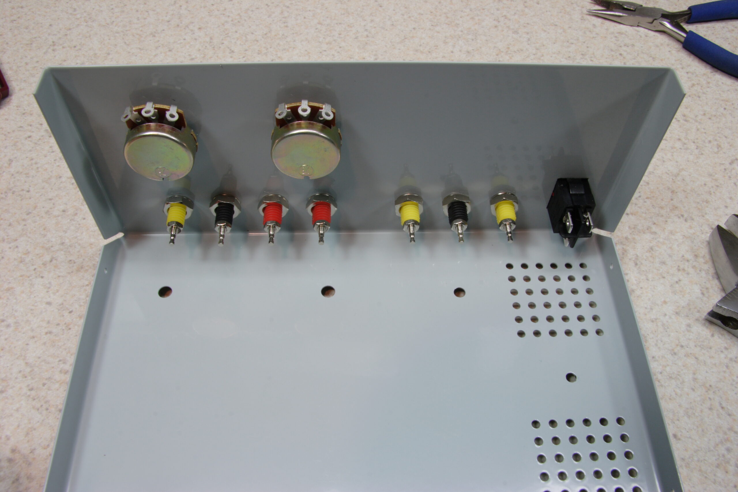
The biggest problem I have with the kit is how the leads connect to the heatsink’d ICs and that the front mounted pots aren’t fine enough for my needs, but it should be trivial to work around this. I’ll just add another pot in series with the existing one, probably something an order of magnitude lower than the current one, and it’ll function as a ‘fine’ control. When the chassis is open for adding these fine controls, I’ll also add some heatshrink tubing around the leads on those ICs. This is just to ensure that a solid physical jolt to the chassis won’t inadvertantly cause some of the leads to touch, causing a short.

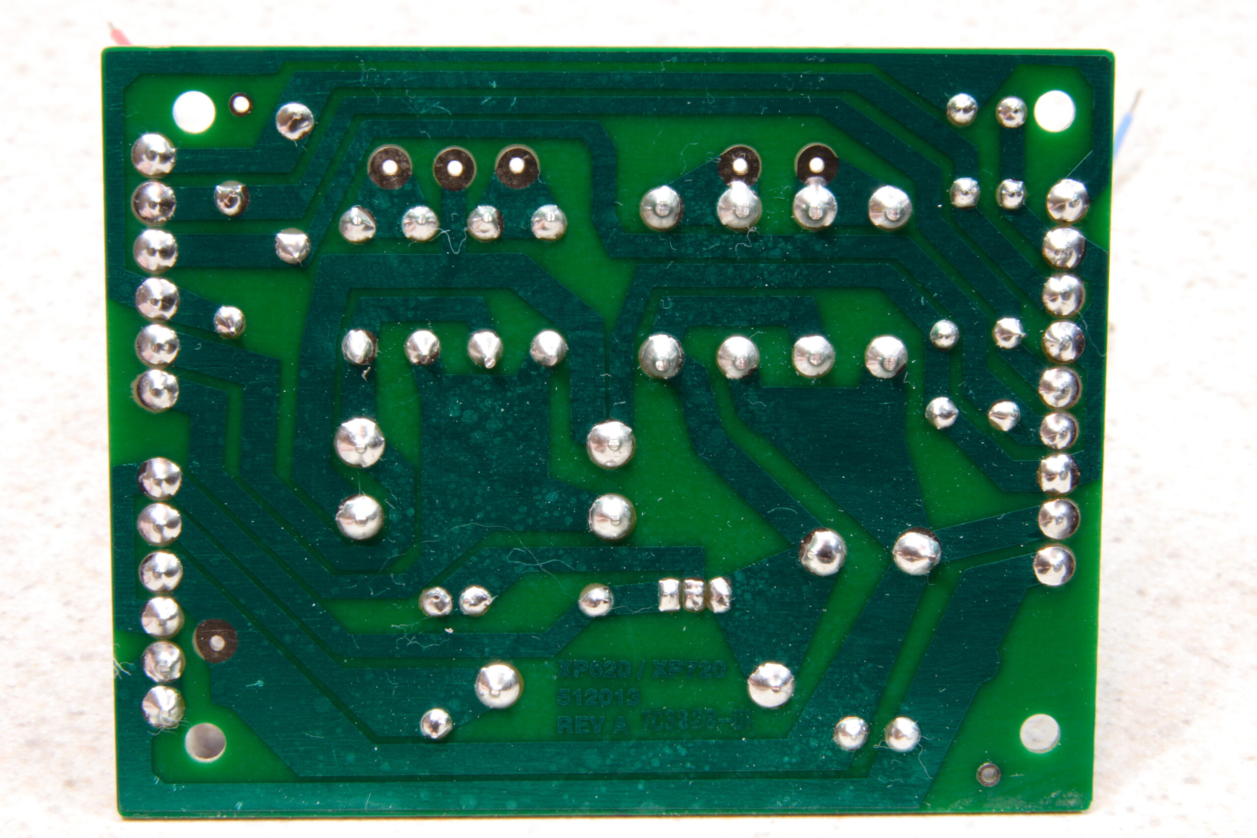
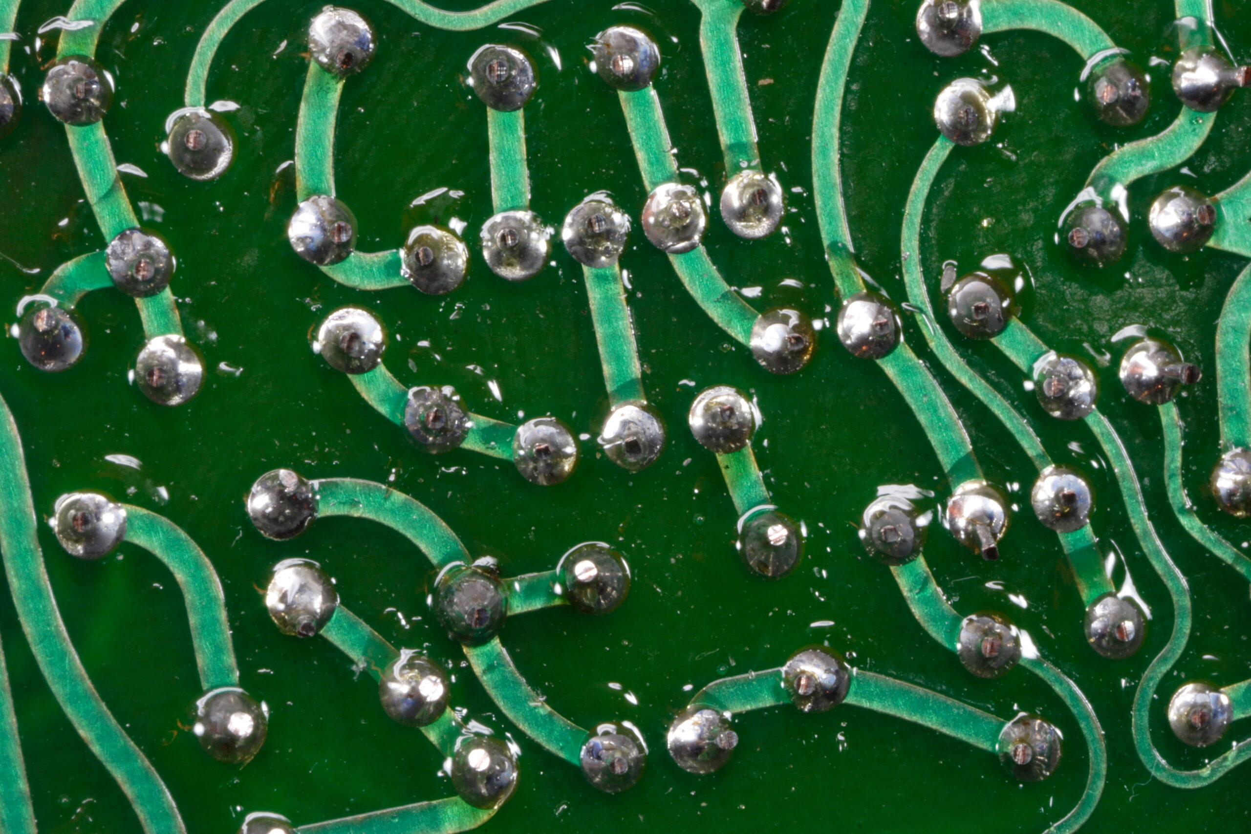
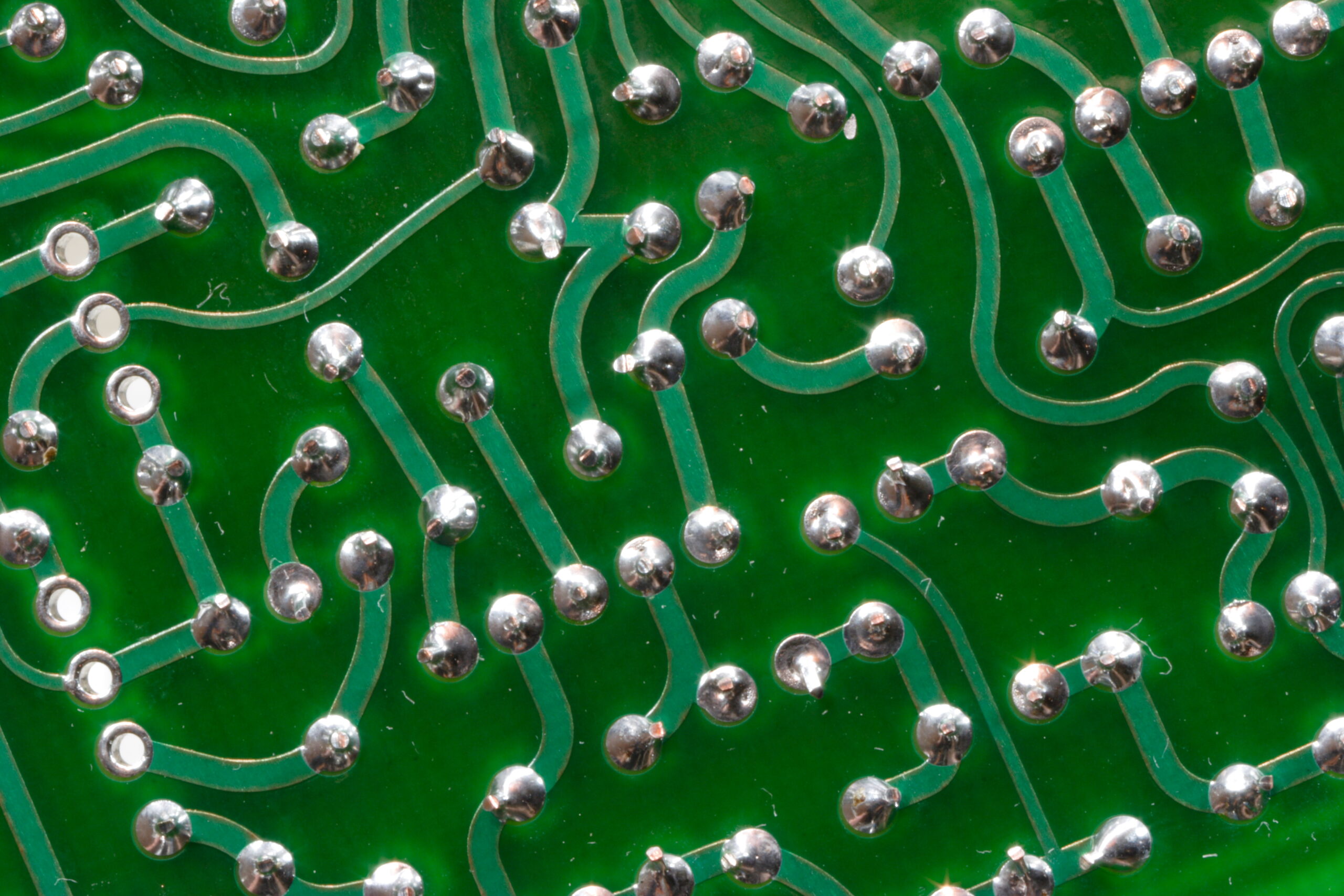
Oh, the only other complaint about it (and this isn’t much of a complaint) is that the pads on the bottom of the PCB are gigantic. While this may be appropriate for some of the larger diodes, it took quite a bit of solder to cover the pads, and it seemed overkill for the various leads. It’s possible that this kit’s educational nature may be another reason for the large pads, though. Maybe to make it easier for those with large-tipped irons or those just getting started to successfully complete the kit. Again, not much of a complaint, just something which was a bit of a frustration.

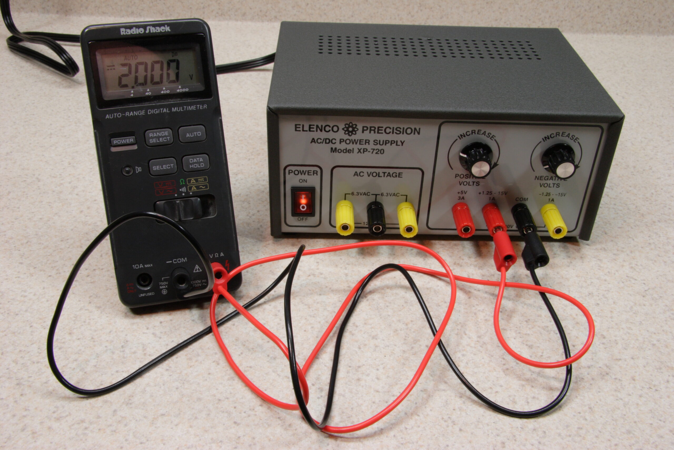
In the end, I’m quite glad I picked up this kit, and I’d have to recommend it to anyone else who needs a simple, low-cost benchtop power supply. It was easy to build, went real smoothly, gave me something to do for an evening, and it works as advertised. With the addition of some stacking banana plug cables, you can hook it up to a spare DMM and whatever you are powering at the same time, making it easy to see exactly what voltage is being sent, and change things without re-plugging anything.

Here’s some photos from my gallery showing various stages of the construction of the Elenco XP-720K (photo gallery retired):

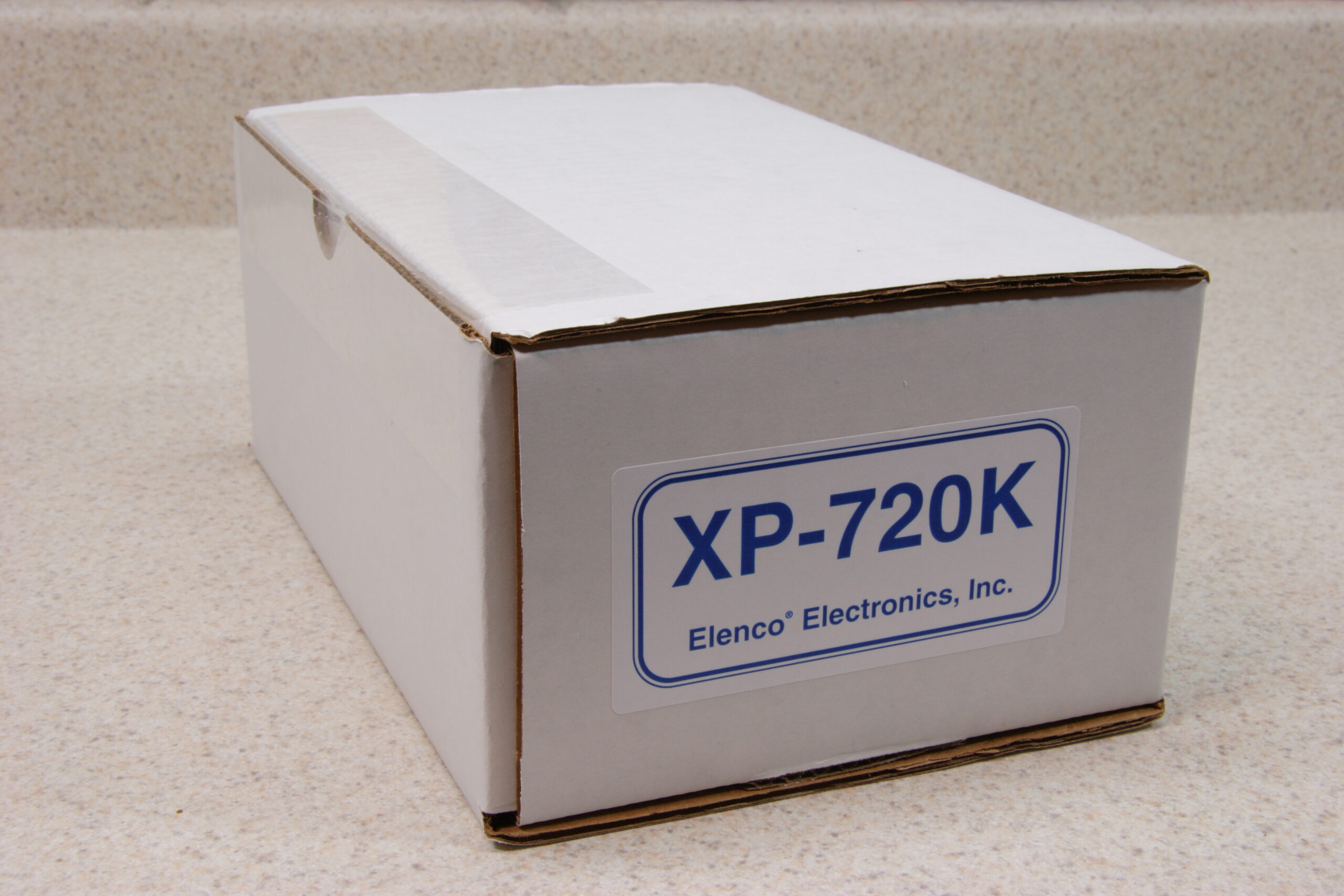
· The Elenco XP-720K comes in a nice, simple box.
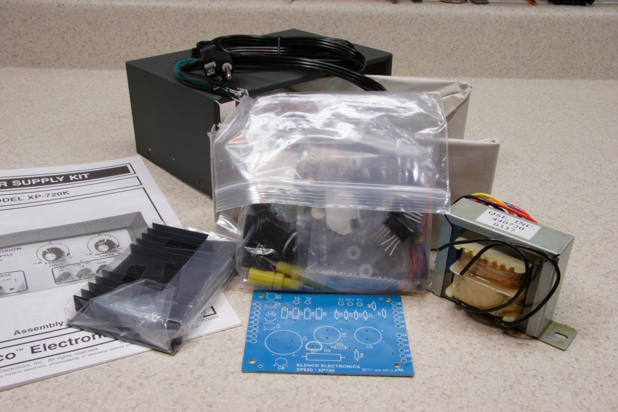
· The pile of parts which came in the box.
· The enclosure is nice, thick, enameled steel.
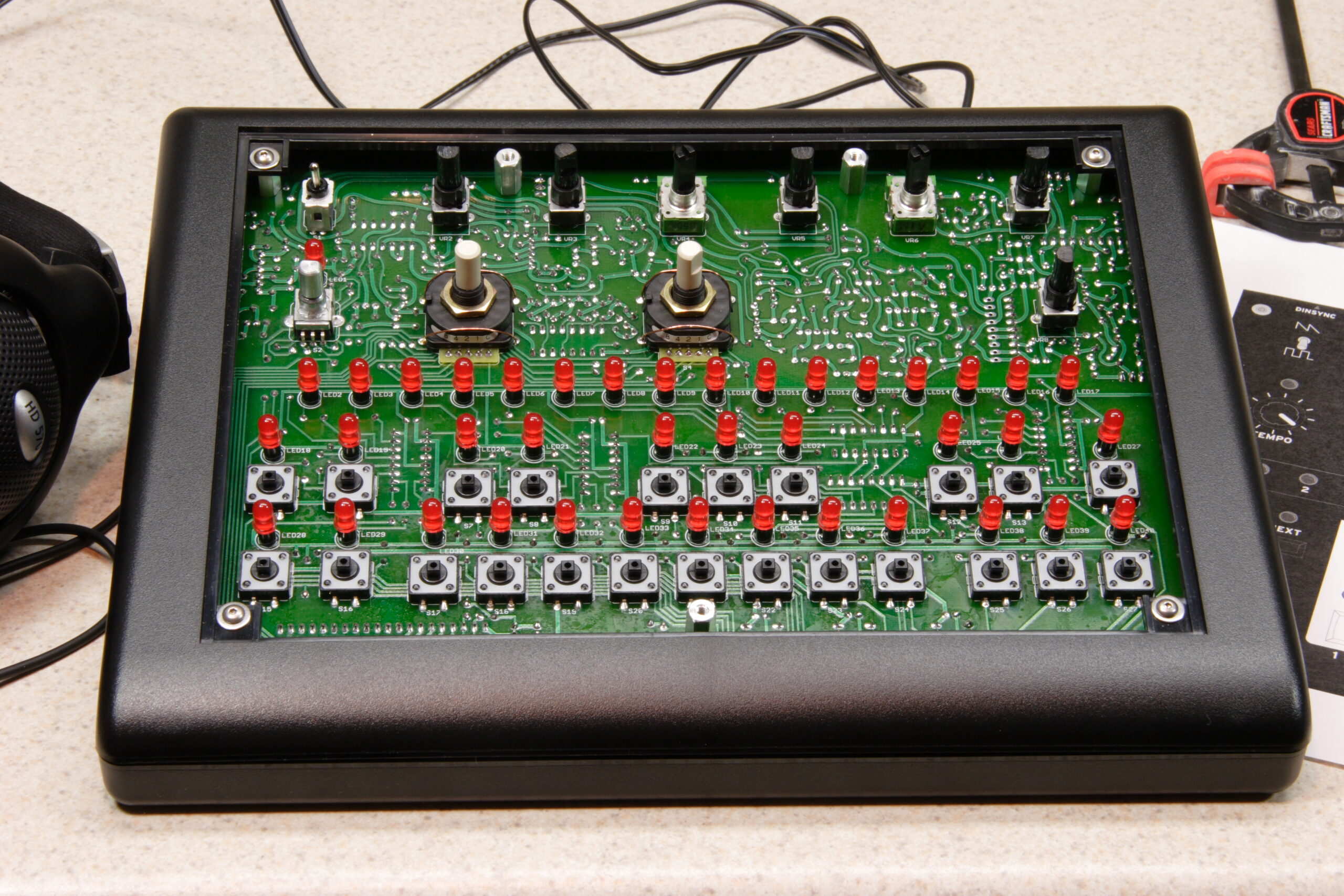
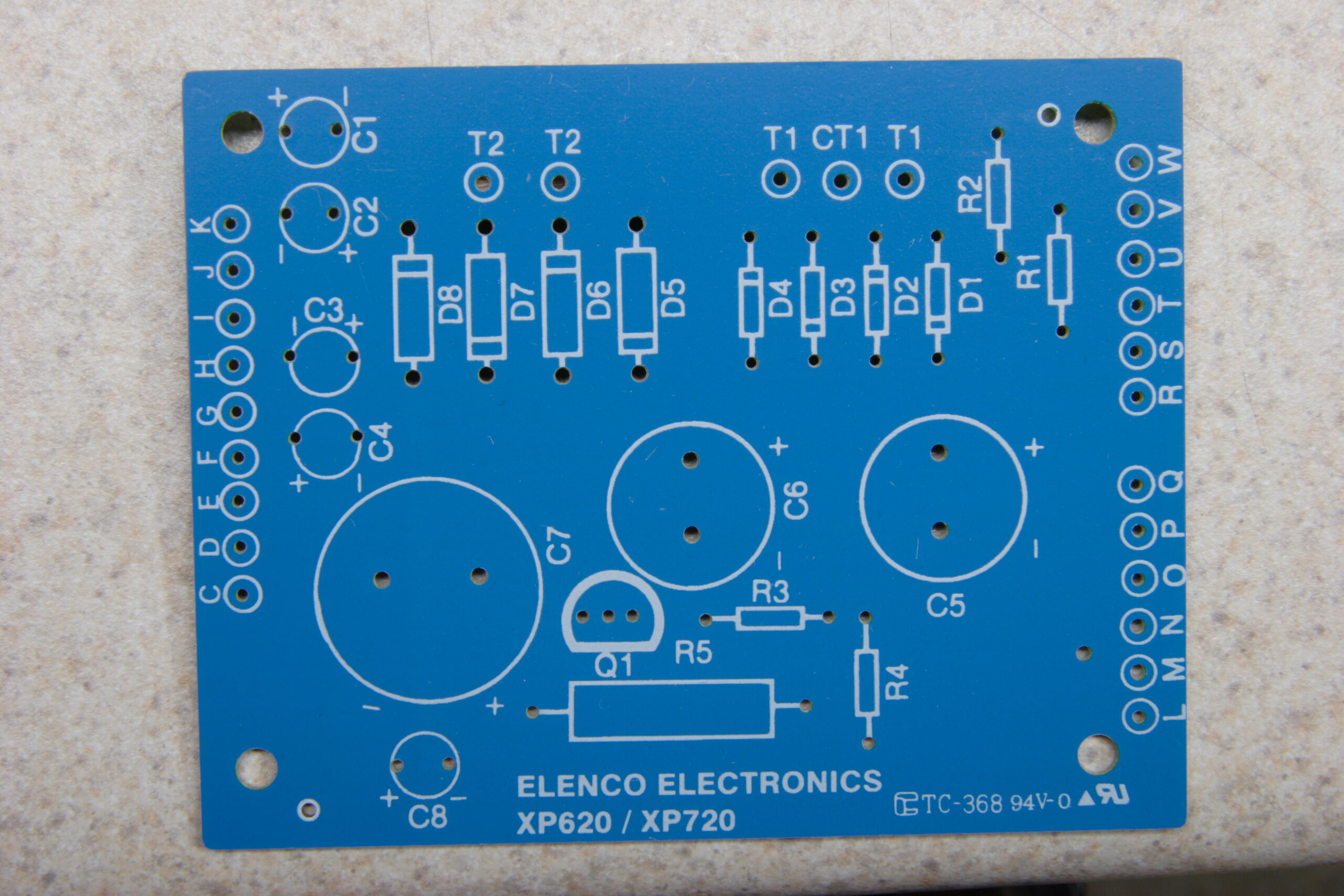
· Detail of the silk screen side of the PCB. No, there aren’t very many parts.
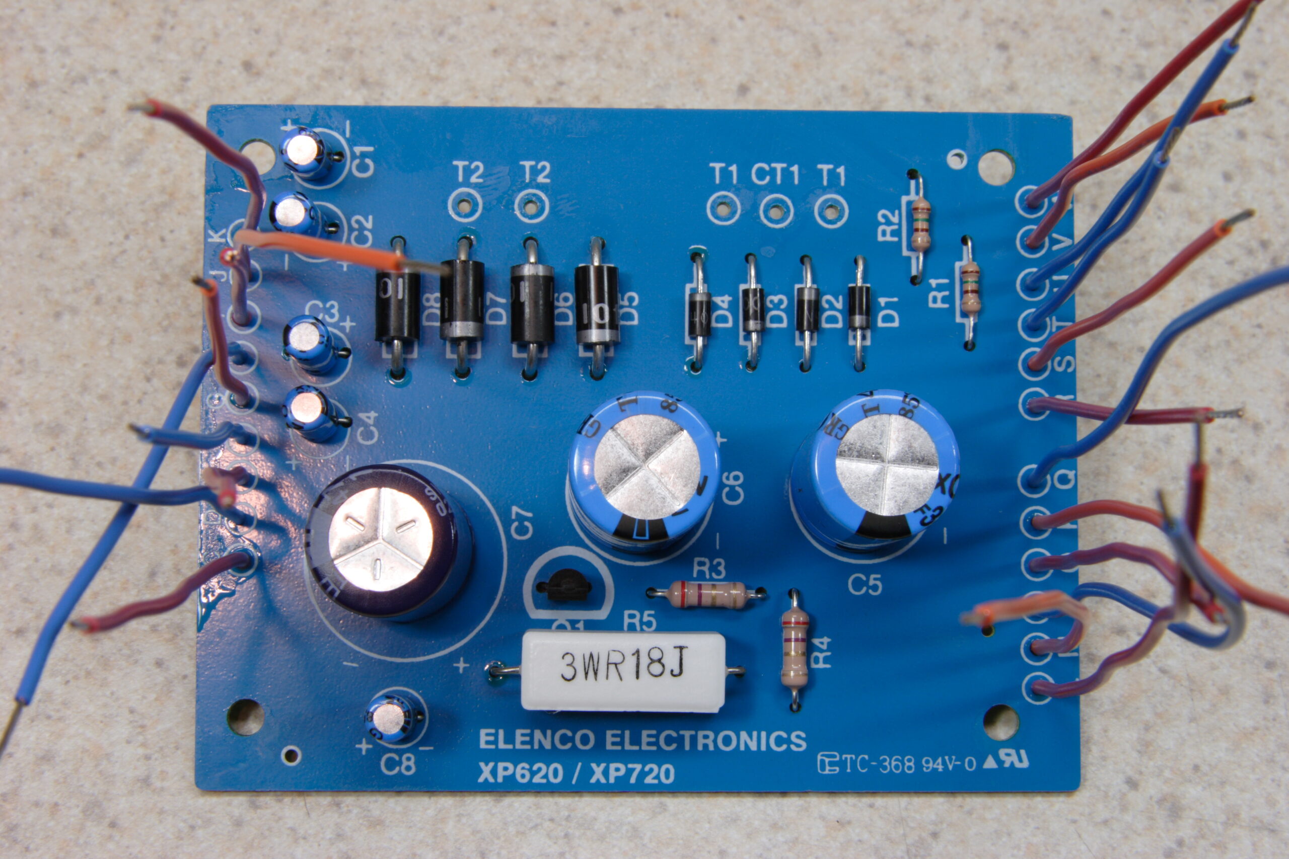
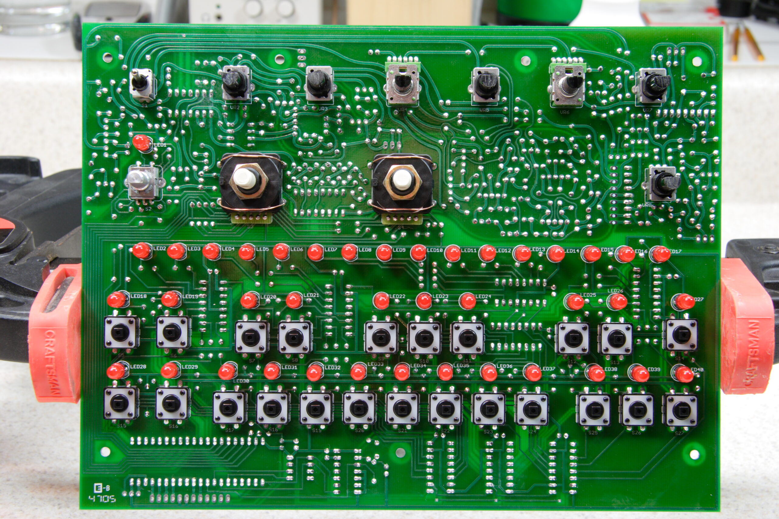
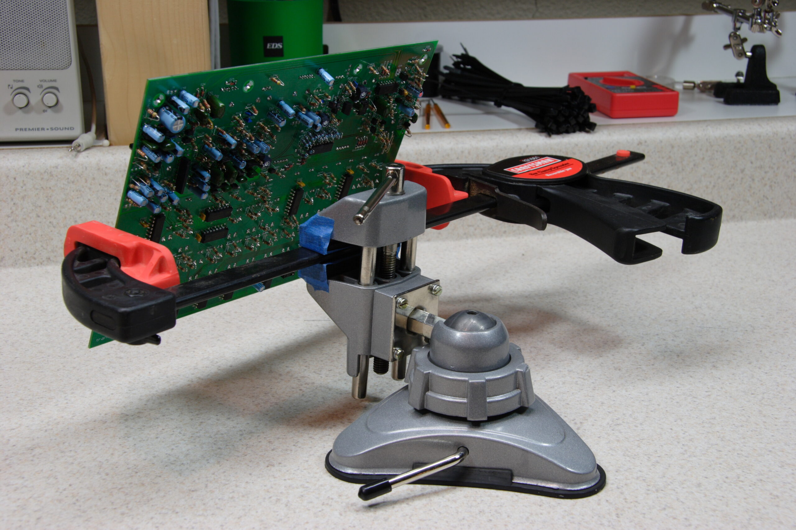
· PCB with all the parts and flying wires installed.
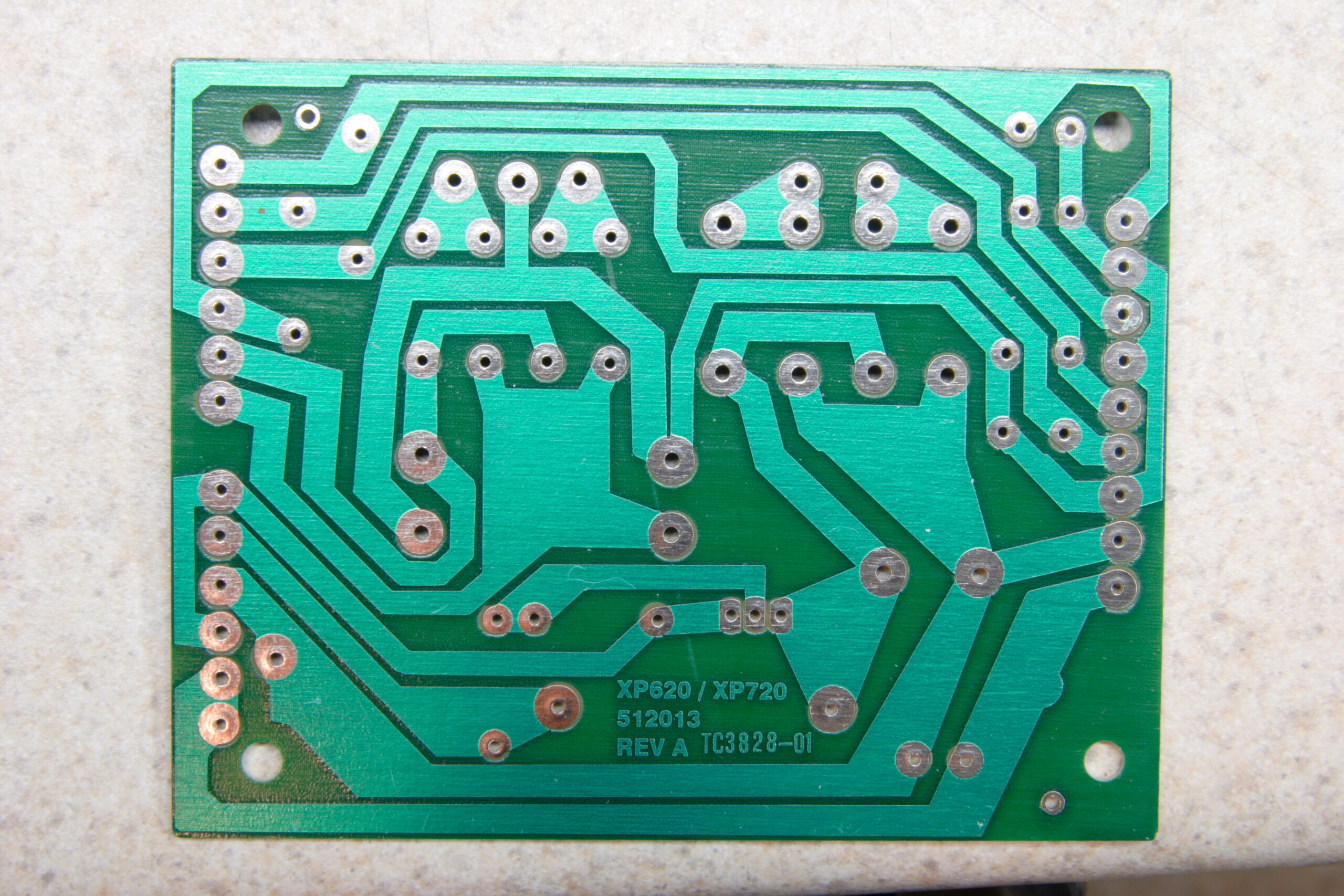
· Solder side of the PCB with all parts installed and flux removed.
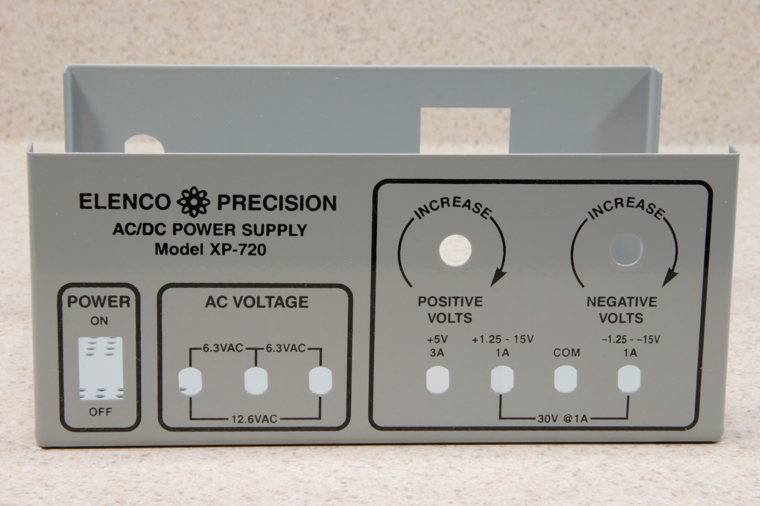
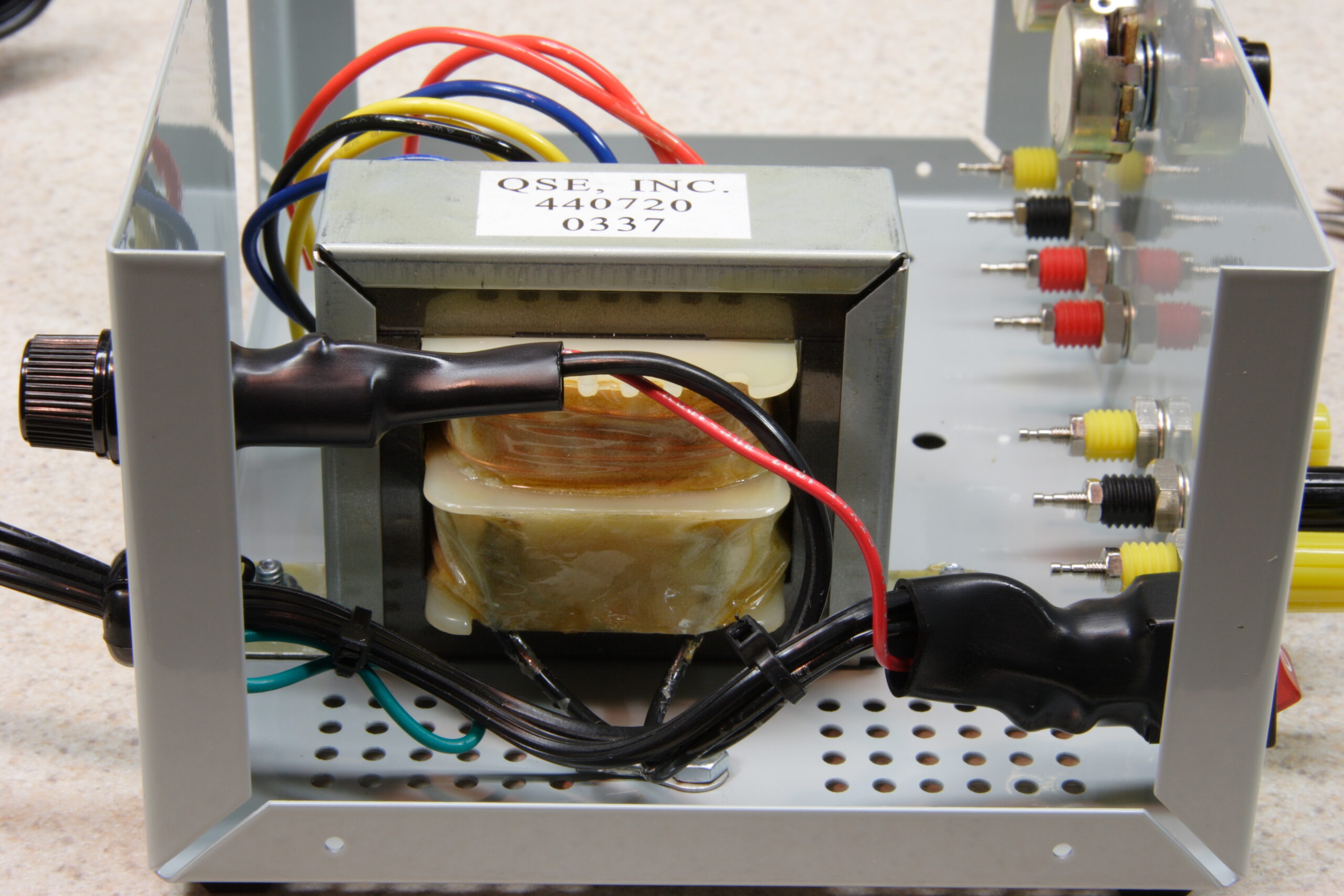
· Chassis with all front panel connections and controls installed, transformer, and mains power connections fitted.
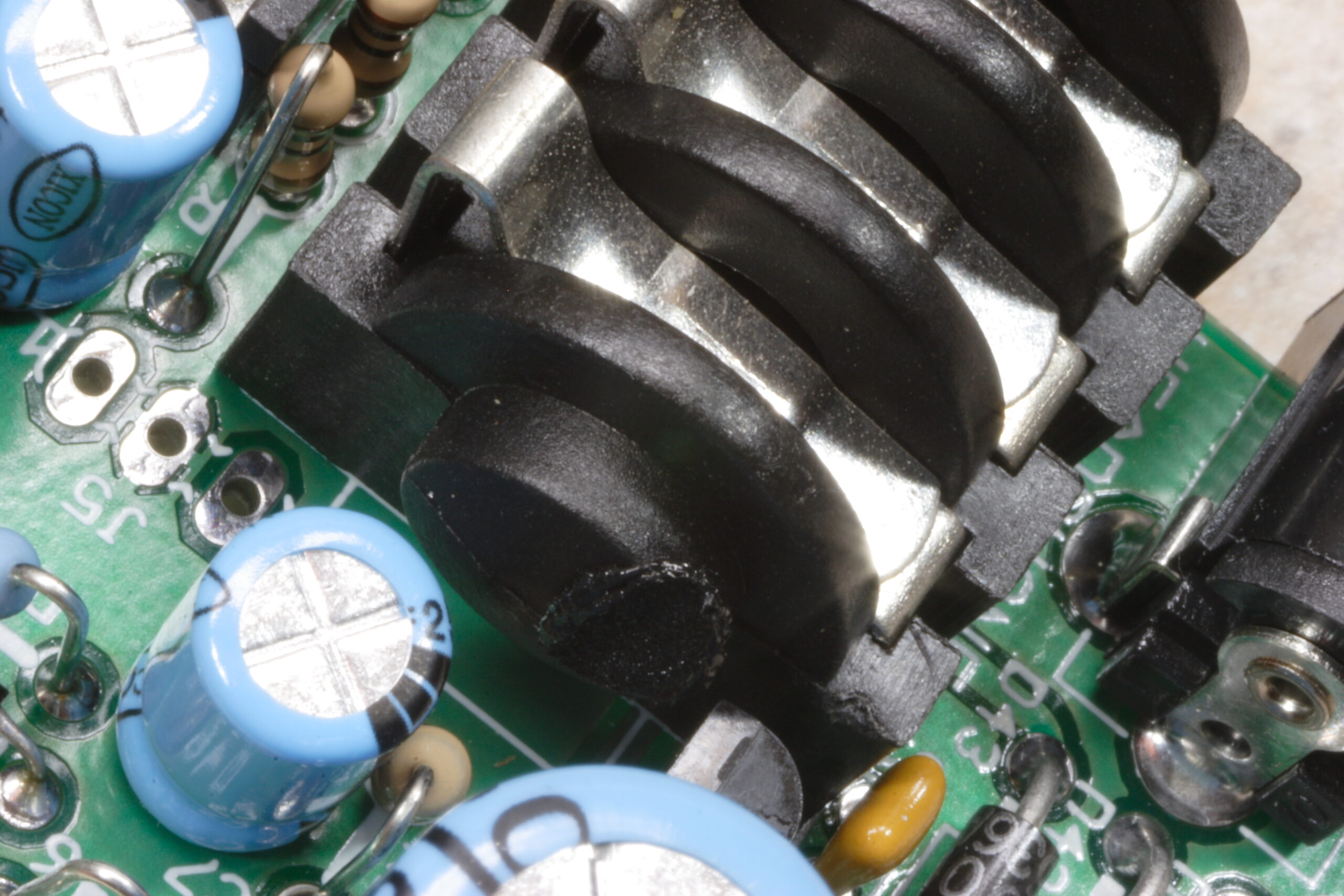
· ICs fitted to the heatsink, with the leads reflow soldered on. These need heatshrink tubing to isolate them.
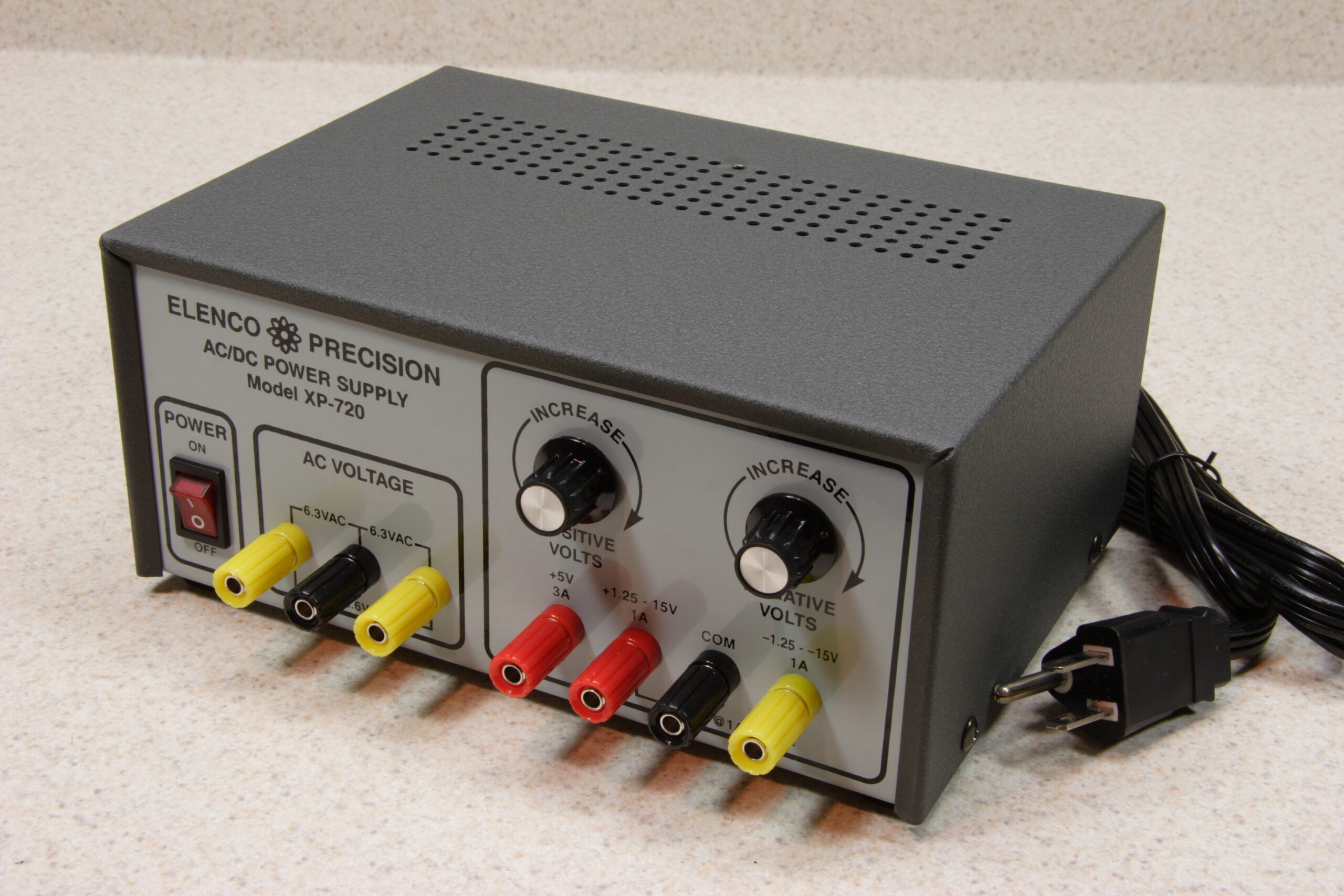
· Looking down into the top of the Elenco XP-720K.
· My completed Elenco XP-720K power supply with the chassis closed.
· While testing the Elenco XP-720K I was able to hit 2.000VDC. This would have been easier with a fine control, which I’ll add later.

electronicsmaking thingsmoved from livejournal

x0xb0x

Well, it works. It’s untuned, uncalibrated, and wholly unfinished. But it makes synthy sounds and appears to not have any problems, except for the LEDs being rather dim.

I’ll worry about that later… For now I need to worry about the new power supply and the new DMM I’m waiting for.

electronicsmaking thingsmoved from livejournal

LEDs


Diffuse and Water Clear Red 1 3/4T (5mm) LEDs
(Click for huuuuuuuuuge…)

I’m just posting this one simply picture because I’m proud of it and I really like it. I just wish I had noticed the dust on them. Or realized that there would be reason to worry about said dust.

electronicsmoved from livejournal

x0xb0x Sequencer LEDs and Switches


x0xb0x Sequencer LEDs and Switches
(Click for more In Progress (photo gallery retired) photos…)

Have I mentioned that I love that macro lens? With the 1:1 extender it’s so, so, so much fun to play with… I only wish I had increased the depth of field there so that focus didn’t fall off so quickly. Still, I like it.

Oh, also, my x0xb0x is mostly done. I say mostly because I’m still waiting for Monday’s delivery of a Mouser order containing a bunch of 2SA733P transistors. The reason is detailed here under the section labeled ‘Picking the right transistors’. These need to be fitted, then I need to test everything.

Somewhere in there I also have to order up the front panel overlays (photo gallery retired), too… I just hope other people want to buy them.

The testing stuff brings up something else. First, I’m worried that my x0xb0x will have some sort of problem. Second, I’m still waiting for a new DMM (a Fluke 179/EDA Kit) to get here so that I can test things accurately, and I’m also waiting for a power supply kit (an Elenco XP-720K) so that I can feed power to various bits of the synth while I’m testing it. After I build the power supply, of course.

So, to make a long story short, I’ve gotten things about as far as they can go for now. I’ll do more later…

In case you are interested, here’s some of the somewhat more notable photos that I’ve taken of the my x0xb0x building (photo gallery retired) thus far, generally marked with their captions from my gallery:

In Progress (photo gallery retired):

· When replacing a resistor in the power supply with a 200Ω one, I accidently melted part of the headphone jack. Whoops.
· Another detailed shot of the FT232BM, the first SMT part I ever soldered, with a millimeter ruler for comparison.
· While soldering, flux is left behind on the PCB. This must be cleaned off afterwards. The flux can be seen here as clearish blobs over the solder.
· Ahh, that’s better. This is a part of the board after I removed the flux with isopropyl alcohol and a toothbrush.
· Main panel with everything but a few 2SA733P’s in it. Note the red LEDs.
· My hacked together panel vise substitute.
· Everything seems to line up with the front panel…

Parts (photo gallery retired):

· A pile of the red diffuse LEDs I ordered from Digi-Key.
· A pile of the water clear red LEDs which came with the x0xb0x.
· Pile of LEDs in 0.22″ standoffs, ready for installation.
· A red keycap on one of the tactile switches.

electronicsmaking thingsmoved from livejournal

Illustrator Problems Fixed (Kinda)

Well, I think I got the Illustrator problem described here fixed.

I took a bit of a brute force approach to the problem. To fix it, I did the following:

– Export the whole image at 1000dpi to a PNG.
– Open the PNG in Photoshop.
– See how many pixels off the image is.
– Adjust the part which was ‘off’ by an appropriate many thousandths of an inch in Illustrator.

I’m pretty certain it’s now fixed… When exporting the image at both 300 and 600 dpi, a ‘bump’ is no longer visible.

Hopefully this version, v1.2 (photo gallery retired), will be the final one. Once I’m certain of this I’ll convert it to the format which Maverick likes, which is basically certain parts set to particular colors from a rather restrictive palette.

Hmm. Yeah. Go-home time soon.

electronicsmaking thingsmoved from livejournal

x0xb0x Panel v1.1 & Illustrator Problems

Yep, there’s v1.1. I cleaned up the keys a little, removed the center detent marks, and changed the logo.

GUR. I just realized that I’ve got some screwed up Illustrator problem…

Could someone help me with this? I’ve got screenshots explaining what I’m seeing, and why I think I shouldn’t be seeing it:

First, as you can see here, the white box I use to mask the key spacing line above the black keys appears to extend up a bit higher than it should.

However, if you look at these two screenshots (1 · 2) you can see the following:

– The white key (selected in image 1) has a .5pt border, set so that it is centered on the outside edge. It’s top edge is at Y:270.459pt.
– The white box I’m using to mask the lines (selected in image 2) has no border, and it’s top edge is set to Y:270.209pt.

As you could see, the white box has it’s top edge set .25pt lower than the white key, which should be the width of the bottom half of the border line. Yet it appears as it does here, with a bump sticking up.

So, can anyone tell me what I’m doing wrong? The math is right, and it should work, but it just doesn’t seem to be happening. Thank you very much. :)

electronicsmaking thingsmoved from livejournal

x0xb0x Logo

Well, there’s my first stab at a logo redesign for my new x0xb0x panel. I’m pretty happy with it… The only concern will be if the text at the bottom (the TRANSISTORIZE YOUR WORLD) stuff scales well and will be readable after printing. I think it will…

Anyway, yeah. One more thing on the panel to polish this evening, and it should be ready to go to the printers. As soon as I’ve decided on a print process, that is.

UPDATE: I changed the text at the bottom to be a big larger. It fills out the panel a lot better, and I think it’ll print better. As this whole logo will only be 70 points high, I think the slightly more obvious text is better.

electronicsmaking thingsmoved from livejournal