9090
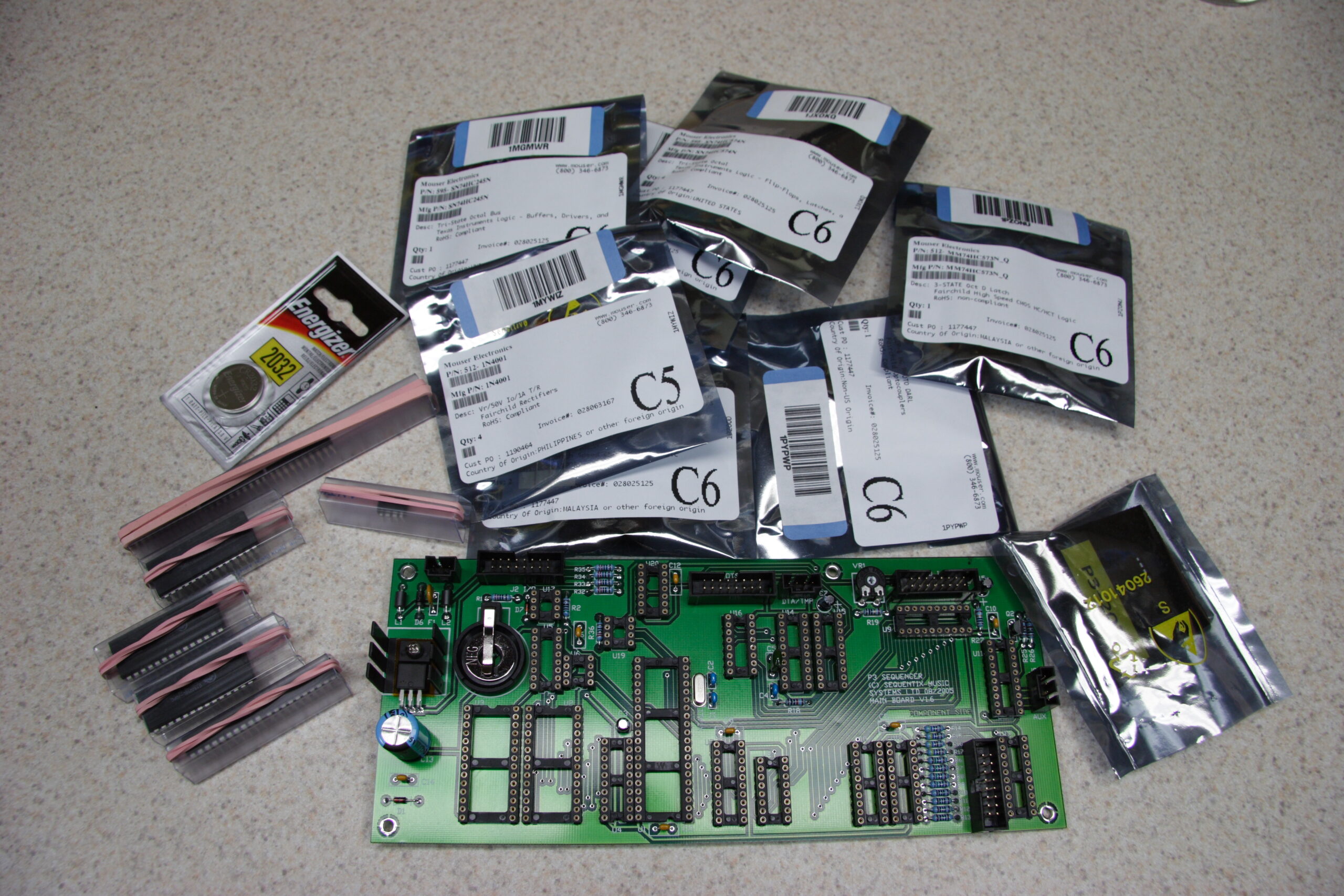
The first round of 9090 parts are here. There are tubes of IC sockets longer than my forearm.
Now a page about the 9090 is up.
I’m also beginning to wish that LJ supported MediaWiki markup. It’s so easy it just sort of flows out of my fingers. Like blood. Only less messy. Usefulness is arguable, though.
UPDATE: Honda / Acura Music Link (Technical) stuff has been moved from dingleberrypie.com, too.

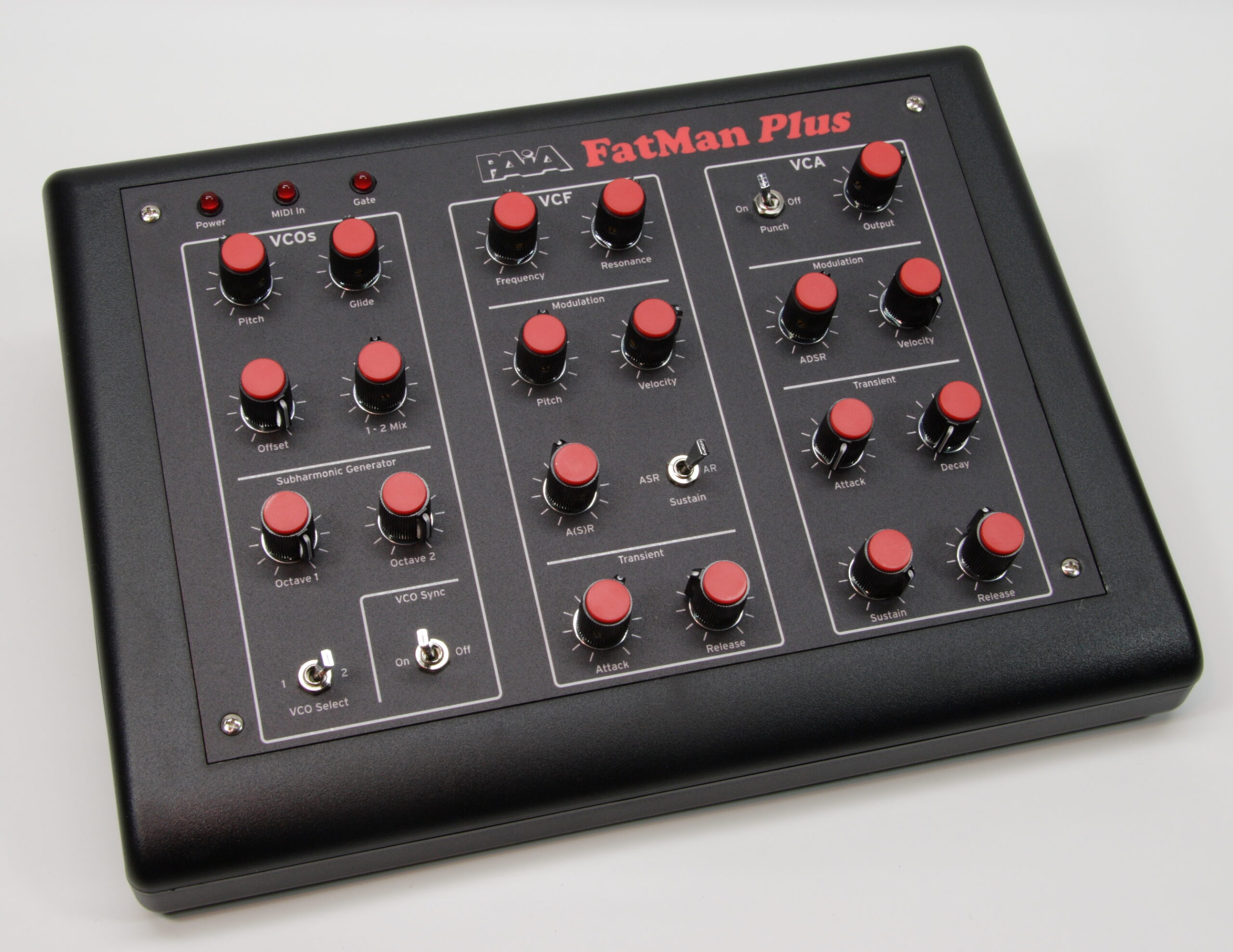
Ah, I finally got around to writing an entry on nuxx.net about the PAiA FatMan Plus. That is, the PAiA FatMan which I rebuilt (and added to) earlier in the year.
Now, just a few more articles to write… the iSight Tripod Adapter, moving the dingleberrypie.com info about Honda electronics in, and a few other things…
Last night I ordered the first round of parts for the PCBs for the TR-9090 I mentioned yesterday. After ordering just the resistors, sockets, diodes, on-board pin headers, and transistors there are 852 parts to be installed, totaling 2546 solder points. This does not count any caps, nor any of the bits from the front panel, MIDI, audio out, etc.
And strangely, Mouser bumped the shipping up to UPS next-day air. I’m not sure why… I think they are dragging their feet a bit on the shipping (overloaded?) so that’s being done to ensure there isn’t a huge delay. No bother, I’ve got other things to do in the mean time.
Now that the Sequentix P3 is done I’ve begun thinking about the next project. A few months back I purchased a PCB set for Trevor Page’s 9090, which is a clone of the synth part of the classic Roland TR-909.
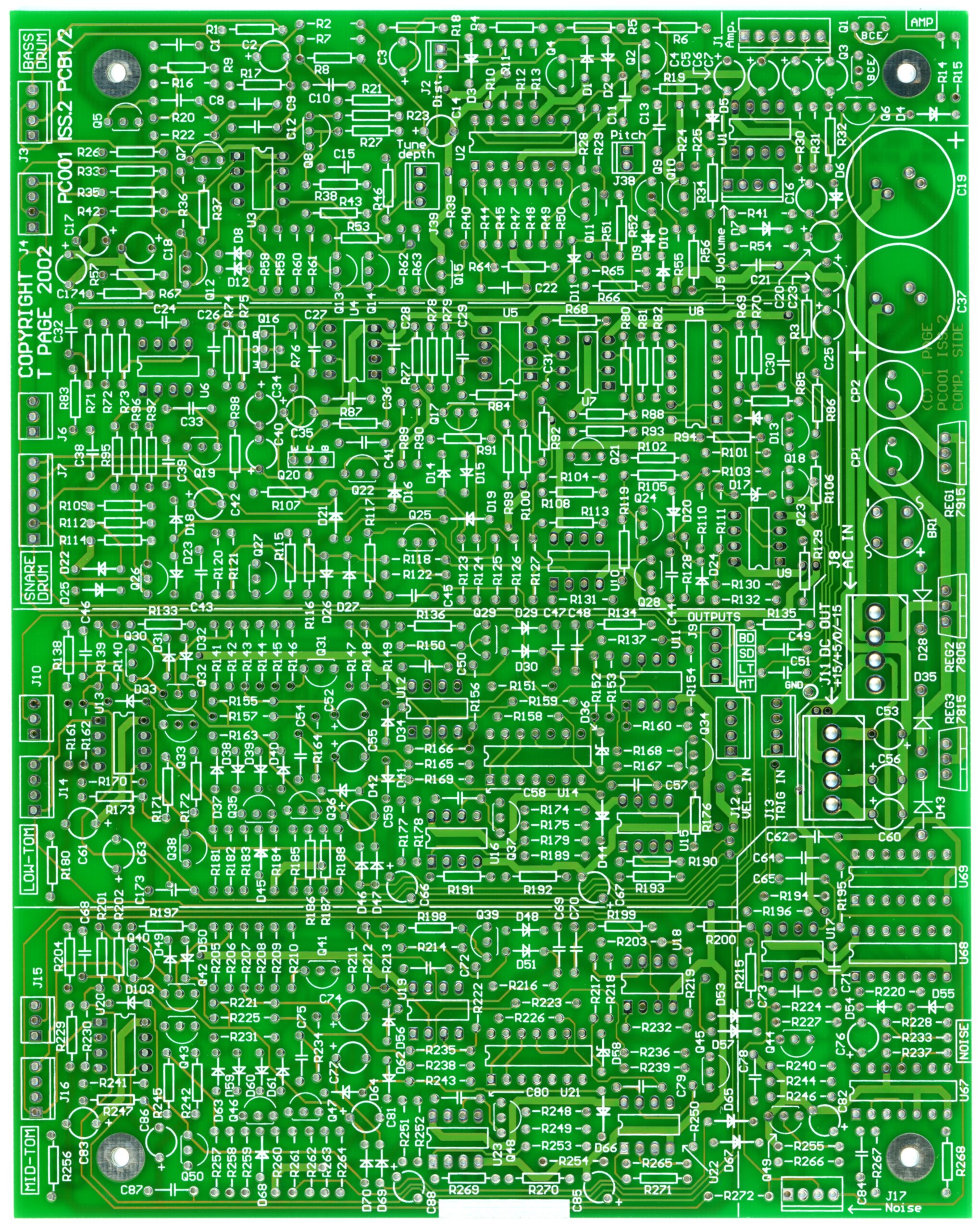
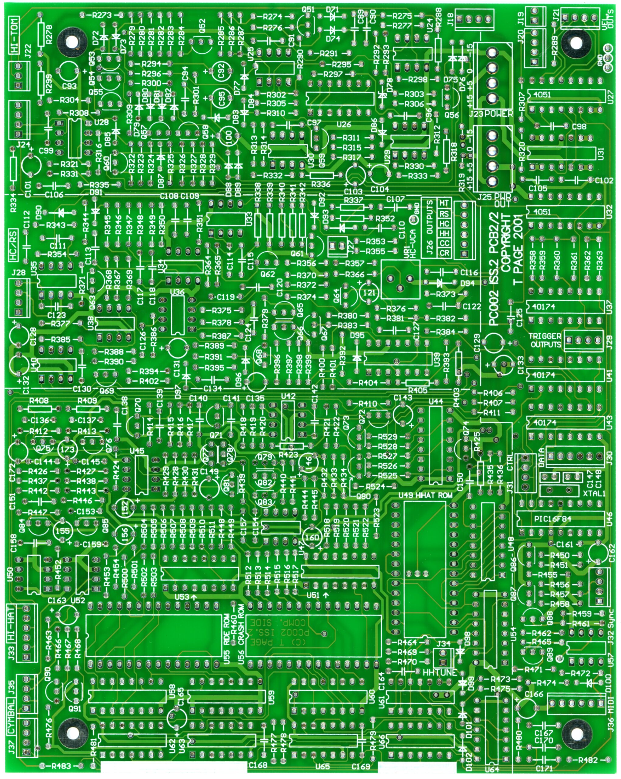
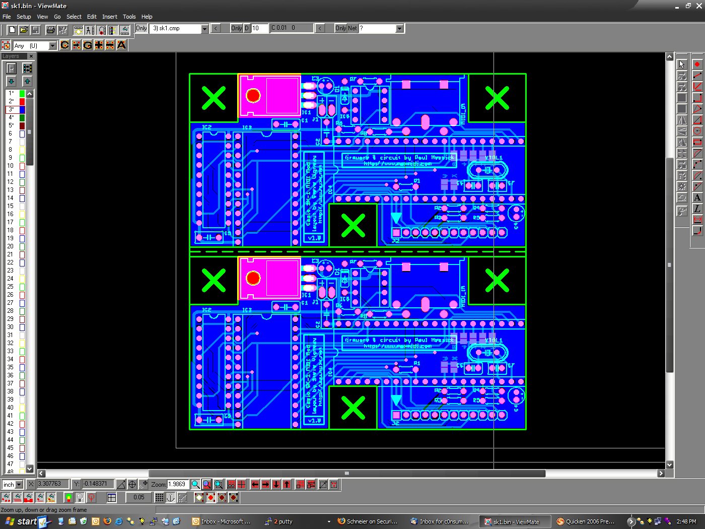
As you can see from the PCBs above, it’s not going to be very simple to build. Additionally, the kit came with just the PCBs, ROMs, and microcontroller. All the other parts need to be sourced myself, and the only thing I have to work from is this PDF parts list. That is, no part numbers, no sums of numbers of parts needed, etc. Designing the case will probably be the most interesting part. I’m hoping to put it in a sloped-front metal enclosure something like one of these, but I’m still not sure yet. For now I’m going to build the boards, figure out the clearances I need, then work from there.
Well, actually, for now I’m going to keep building the part lists…
There are around 92 discreet transistors. And more than 50 IC sockets are needed. This isn’t going to be cheap, either.

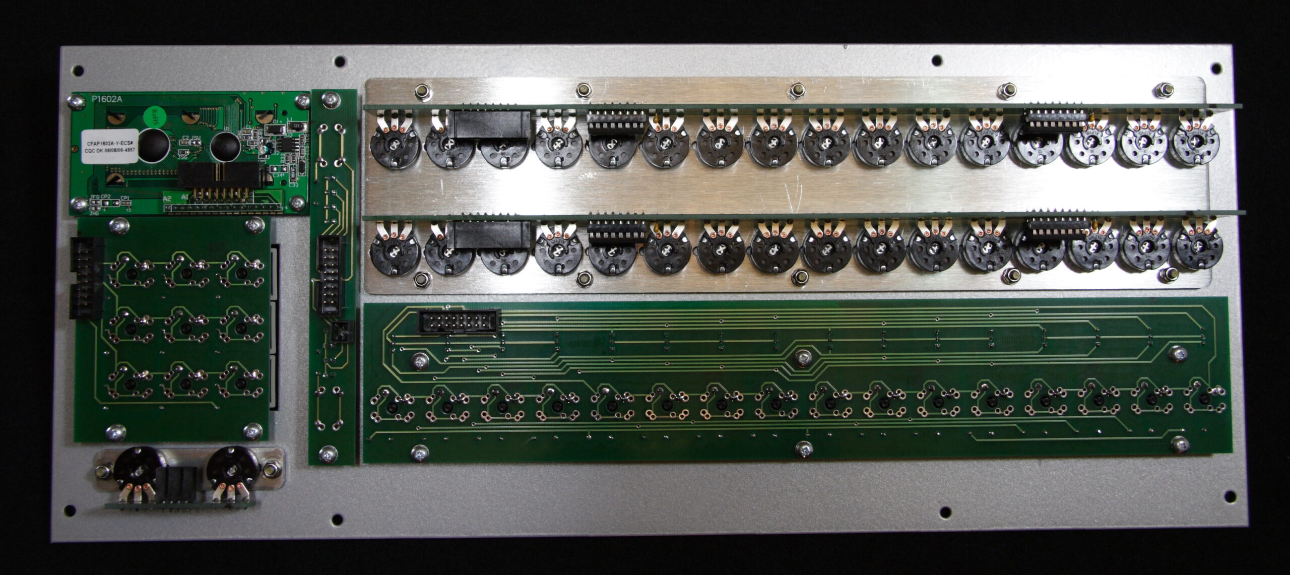
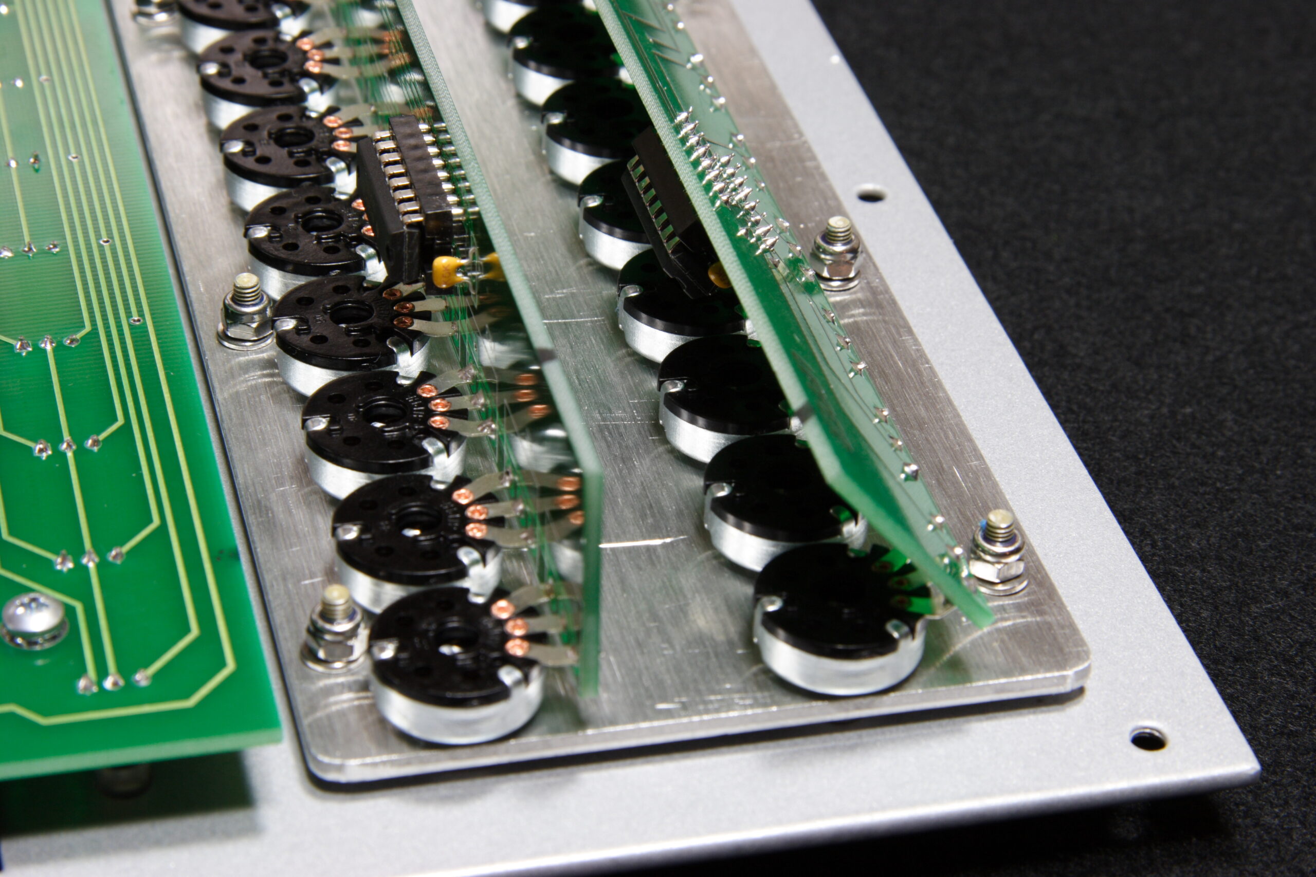
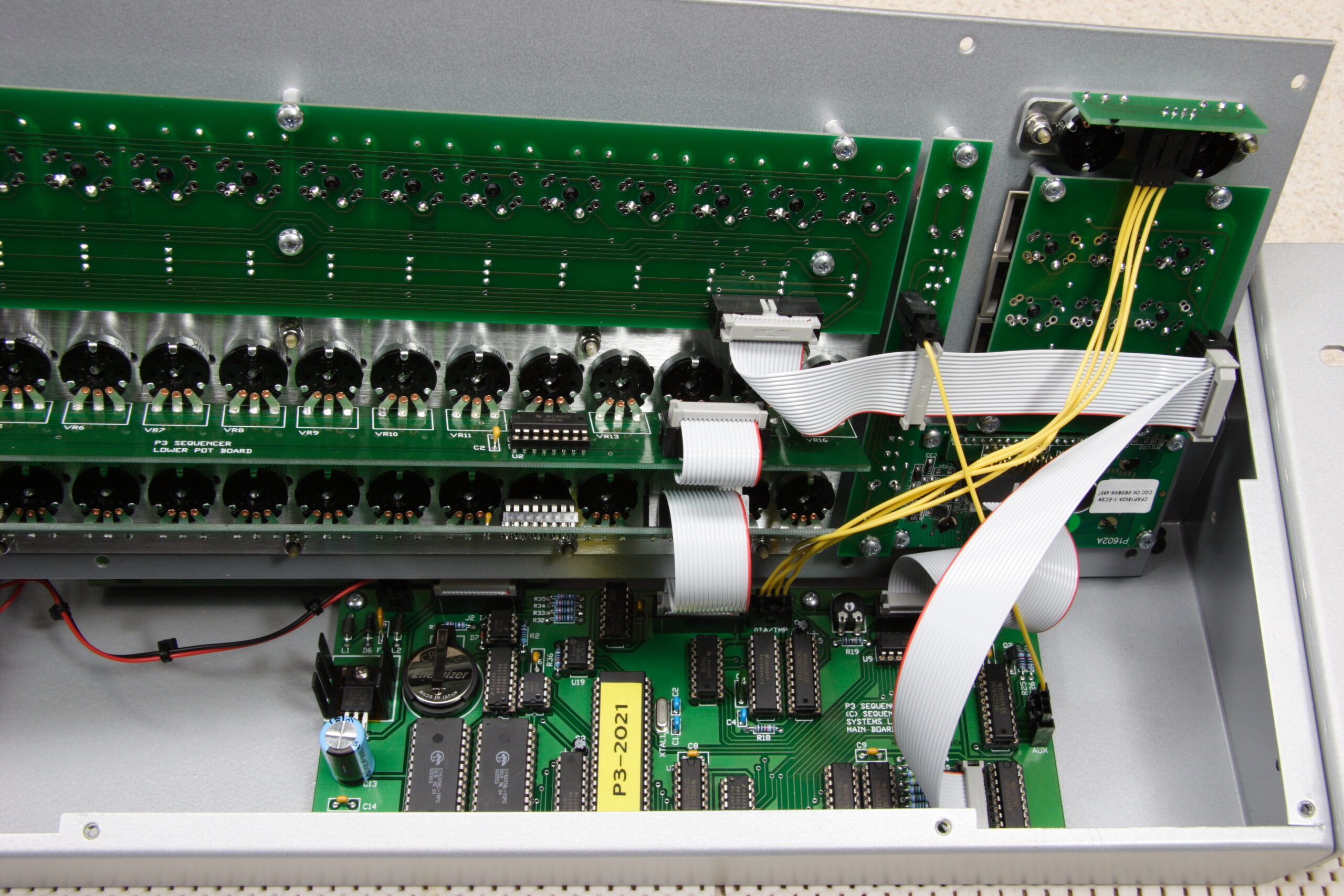
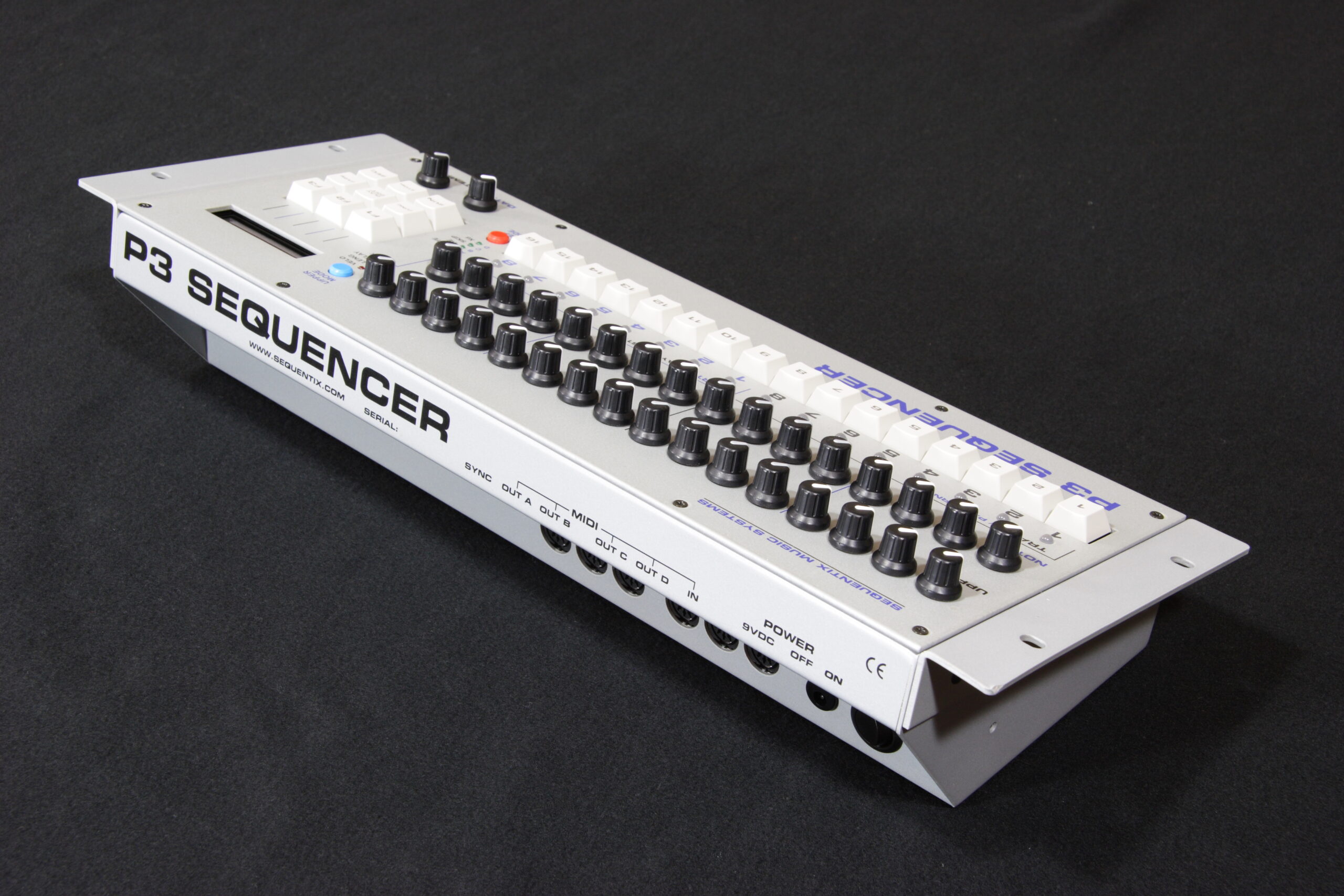
Well, it’s done. After thinking about how to solve the problem and (restlessly) sleeping on it, I ended up realizing that if I bent one of the PCBs back towards the rear of the pots that things would fit into the case properly. (The bend can be seen here.) After that I was able to finish assembling the P3 and get everything up and running.
I had figured that if I bend the board back, either it’ll work or I’ll break some of the pots. If the pots break, I’m back to the worst-case scenario of having to replace all the pots. Clearly they didn’t, so all is good.
Interestingly, after I walked back upstairs to my desk I found that Colin, the guy who runs Sequentix (and a rather nice guy, from what I can tell) had seen my rather frustrated previous post regarding the pots and clearance in the enclosure and wrote to tell me that due to some slight changes he has to bend the top pot board back on production P3s. It was rather reassuring to read that note and know that the problem I ran into wasn’t unique and that the solution of bending the board back is the ‘right’ one.
So, yes. It’s all done. I’ve got a few more photos of everything up online. Here’s the more notable ones:
In Progress Album: (photo gallery retired)
· Main board and a pile of ICs and such for installation.
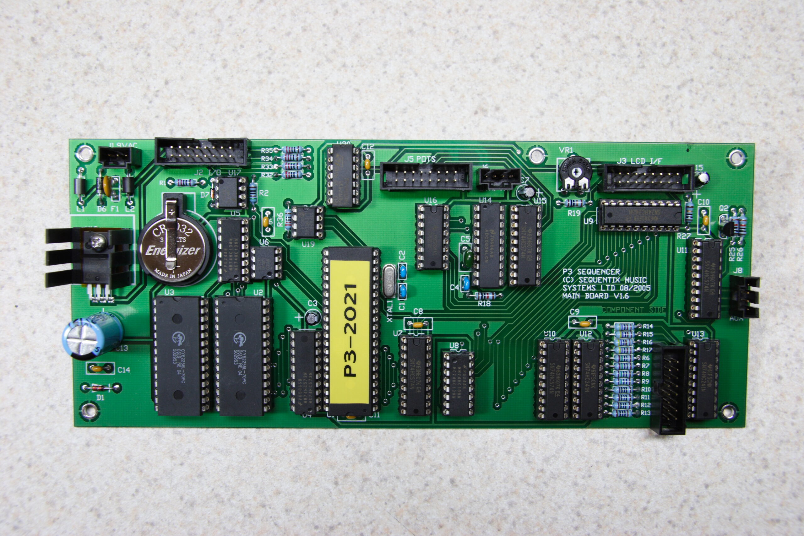
· Wholly populated Sequentix P3 main board.
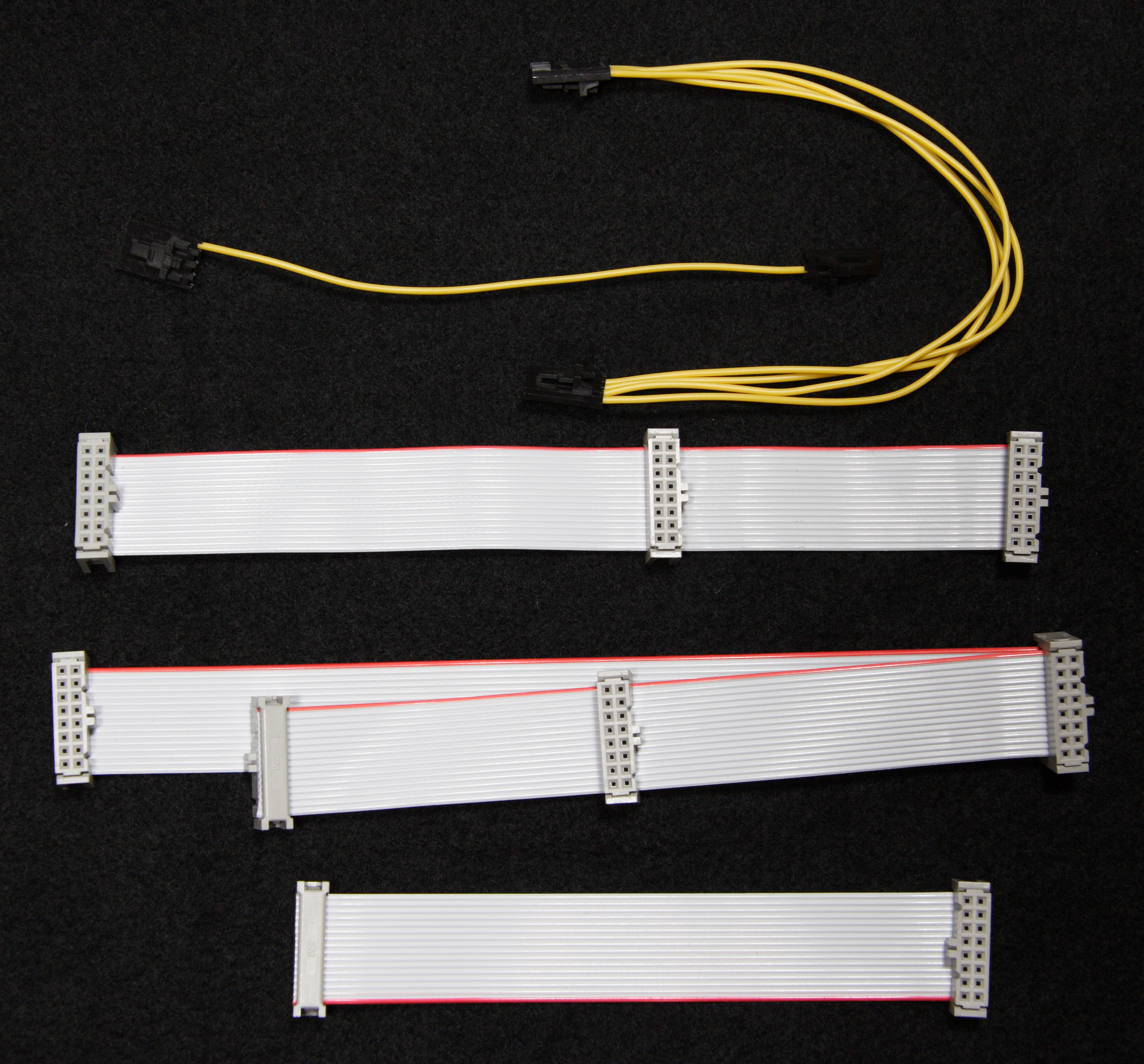
· All cables for connecting the P3 boards, except for the short jumper between the main board and the I/O board.
· Top pot board, bent back so that the enclosure fits together properly.
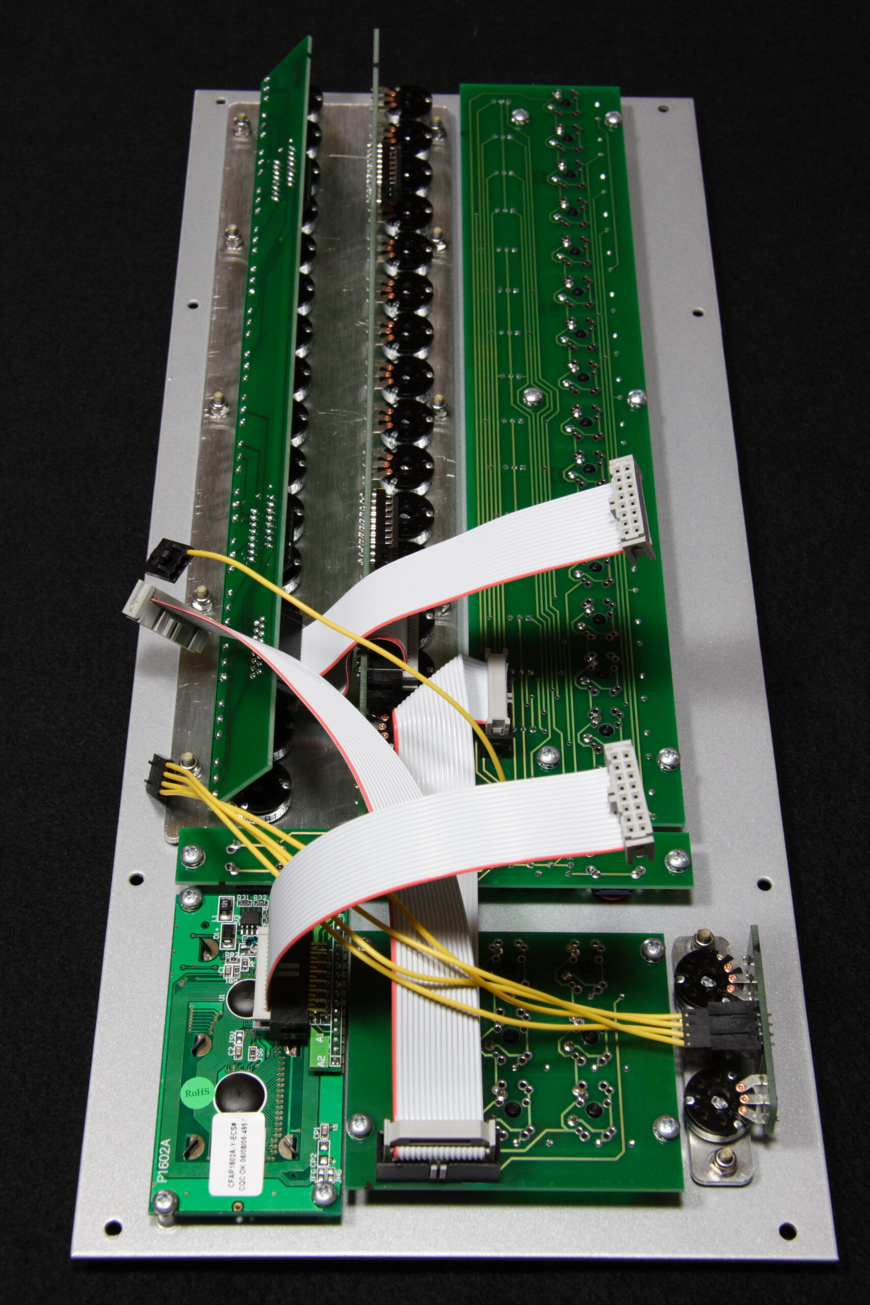
· Sequentix P3 front panel fitted with cables, ready to connect to the bottom of the enclosure and the main board.
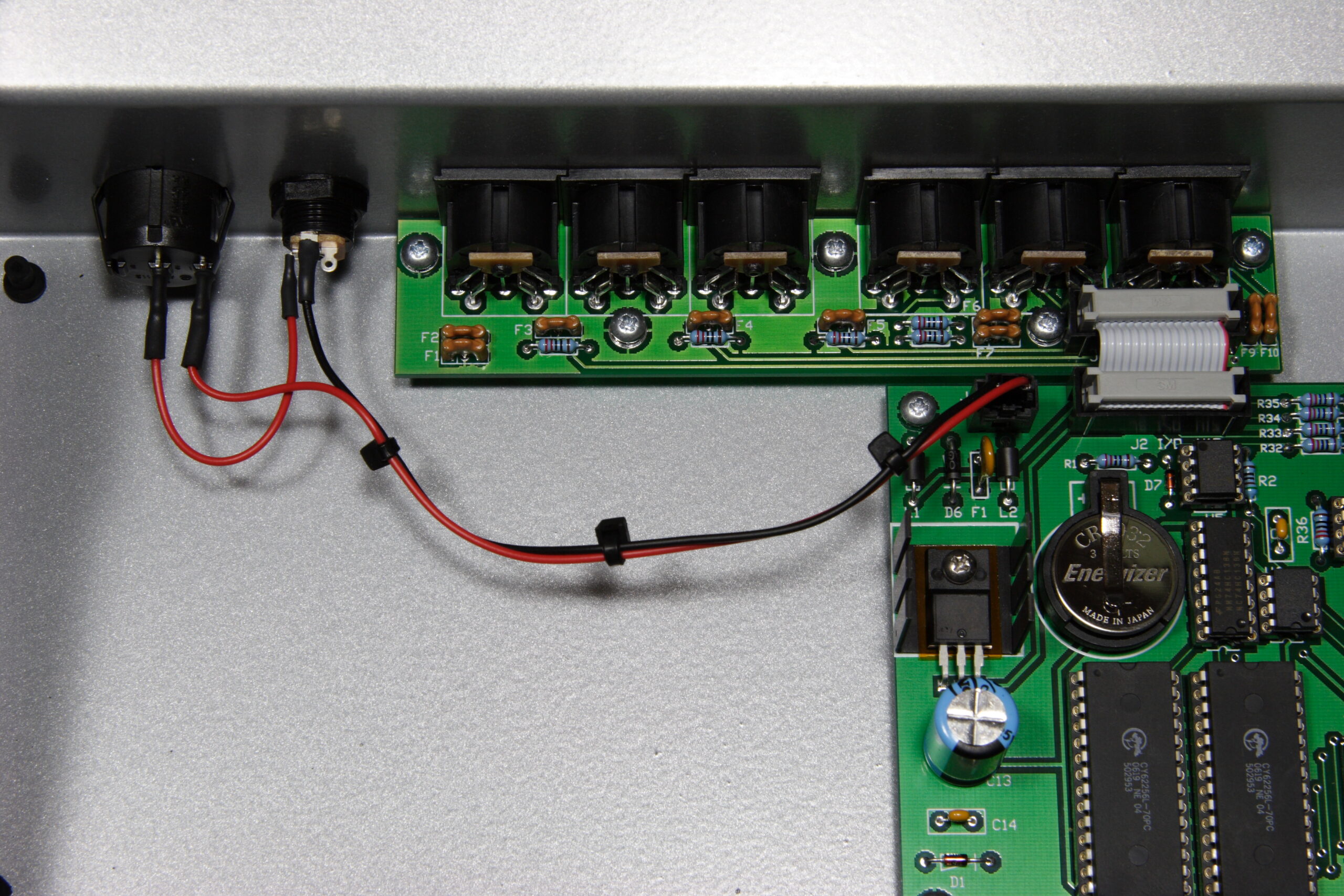
· Inside the bottom of the P3 enclosure, looking at the power connectors, mainboard, I/O board, and jumper.
· All cables inside the P3 enclosure connected, everything ready to close up.
Done! Album: (photo gallery retired)
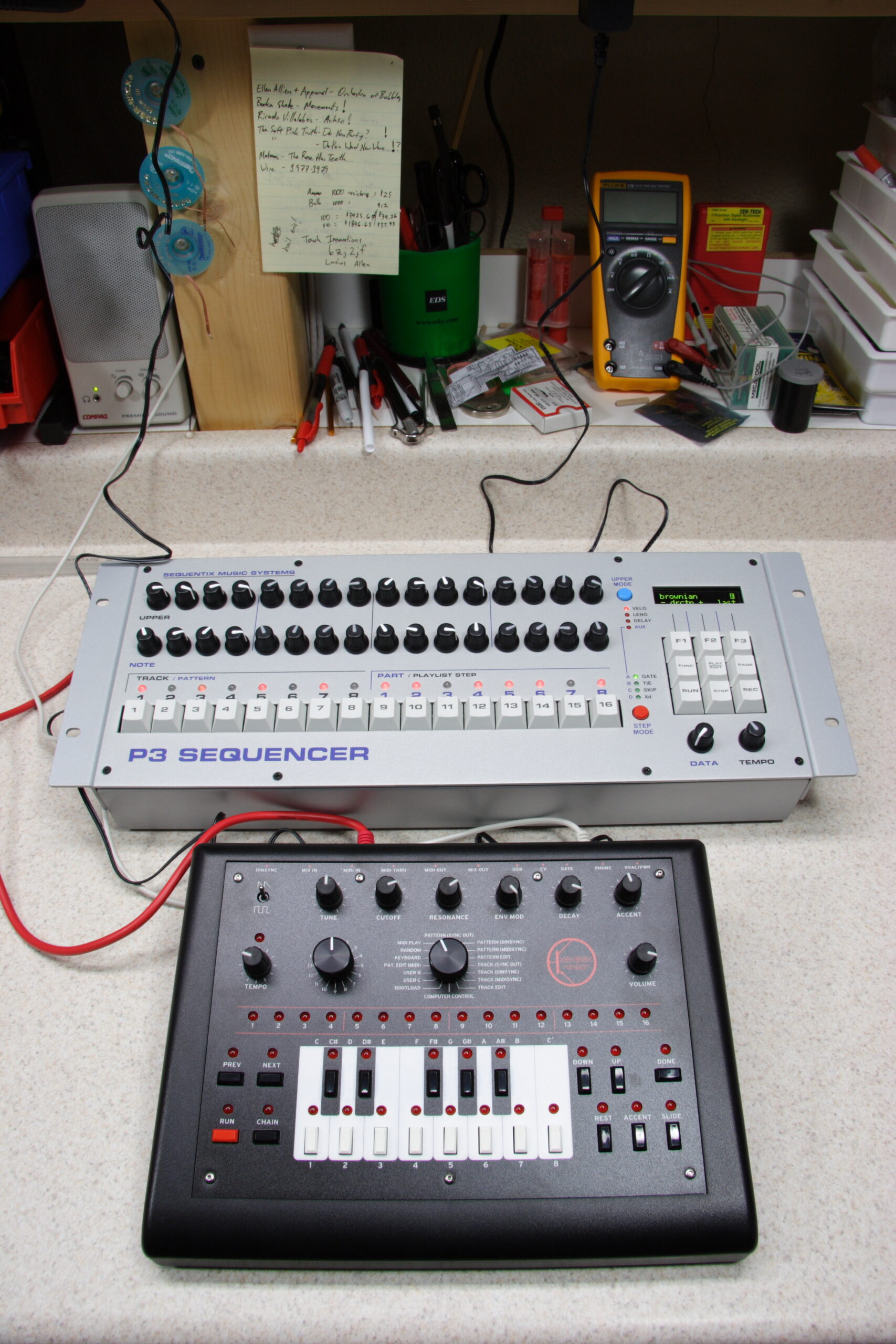
· The P3 triggering the x0xb0x, since it’s a good synth to learn with. I think.
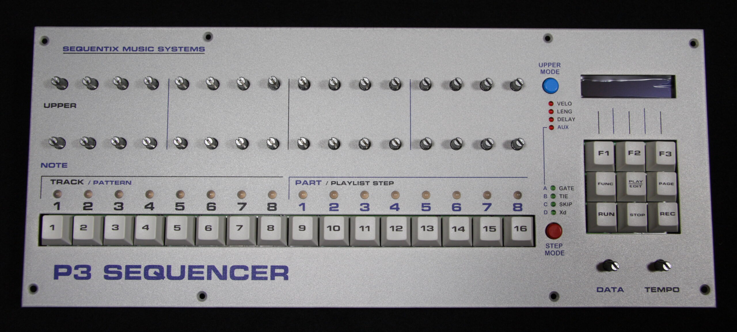
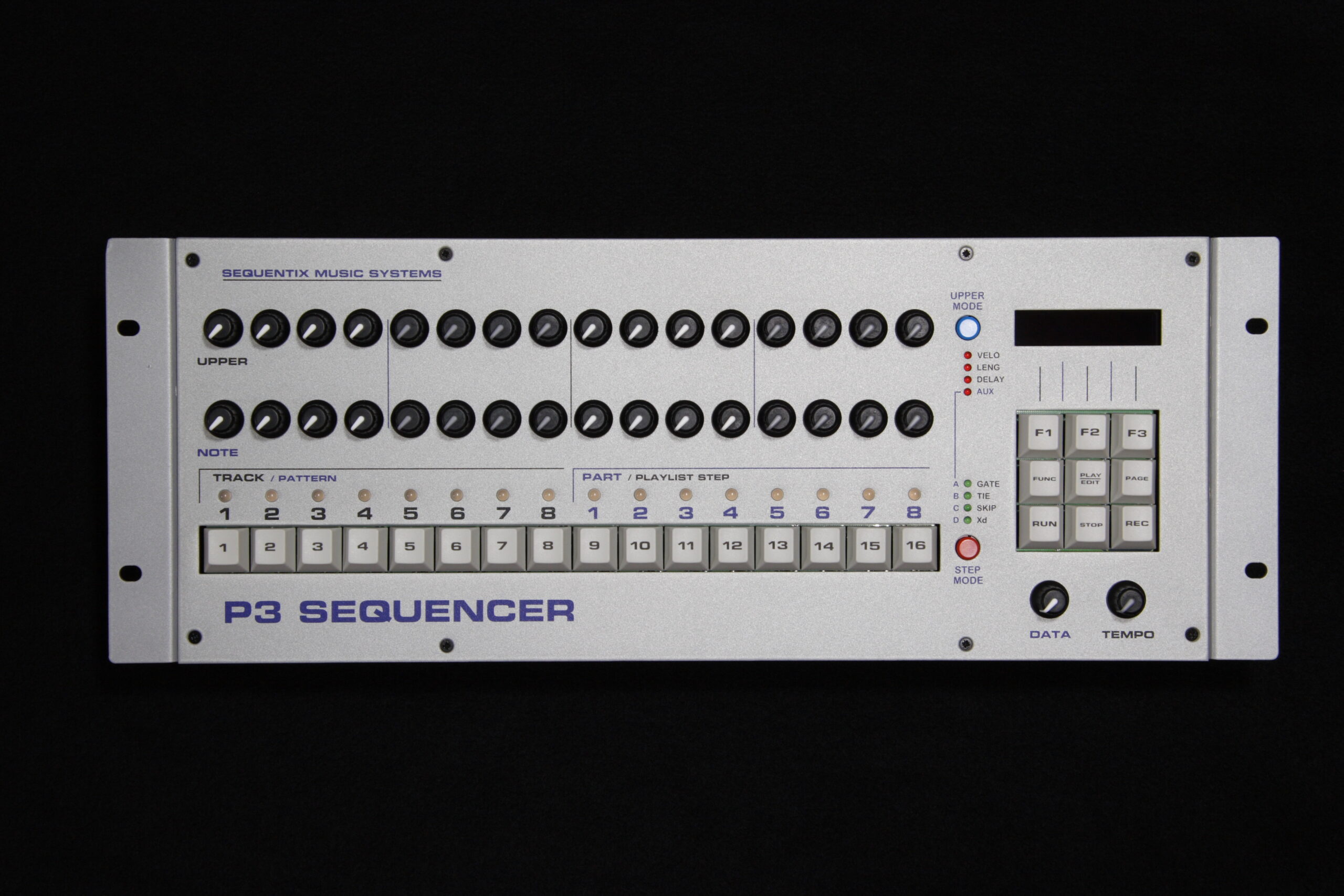
· Front view of the P3.
· Angle view of the P3 booting, as seen above.
· View of the Sequentix P3 showing the rear panel.
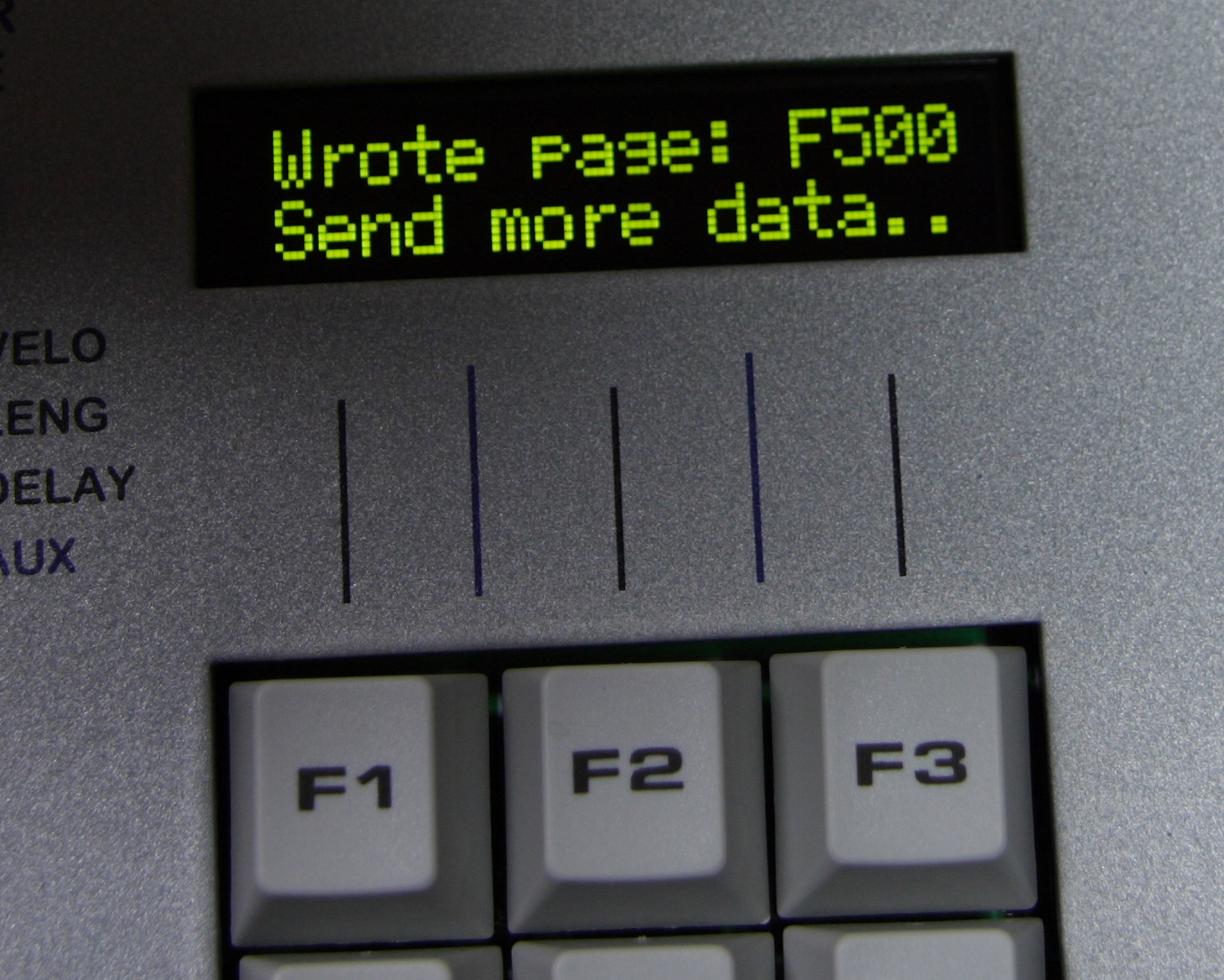
· Sequentix P3 while receiving firmware update as SYSEX data via MIDI.
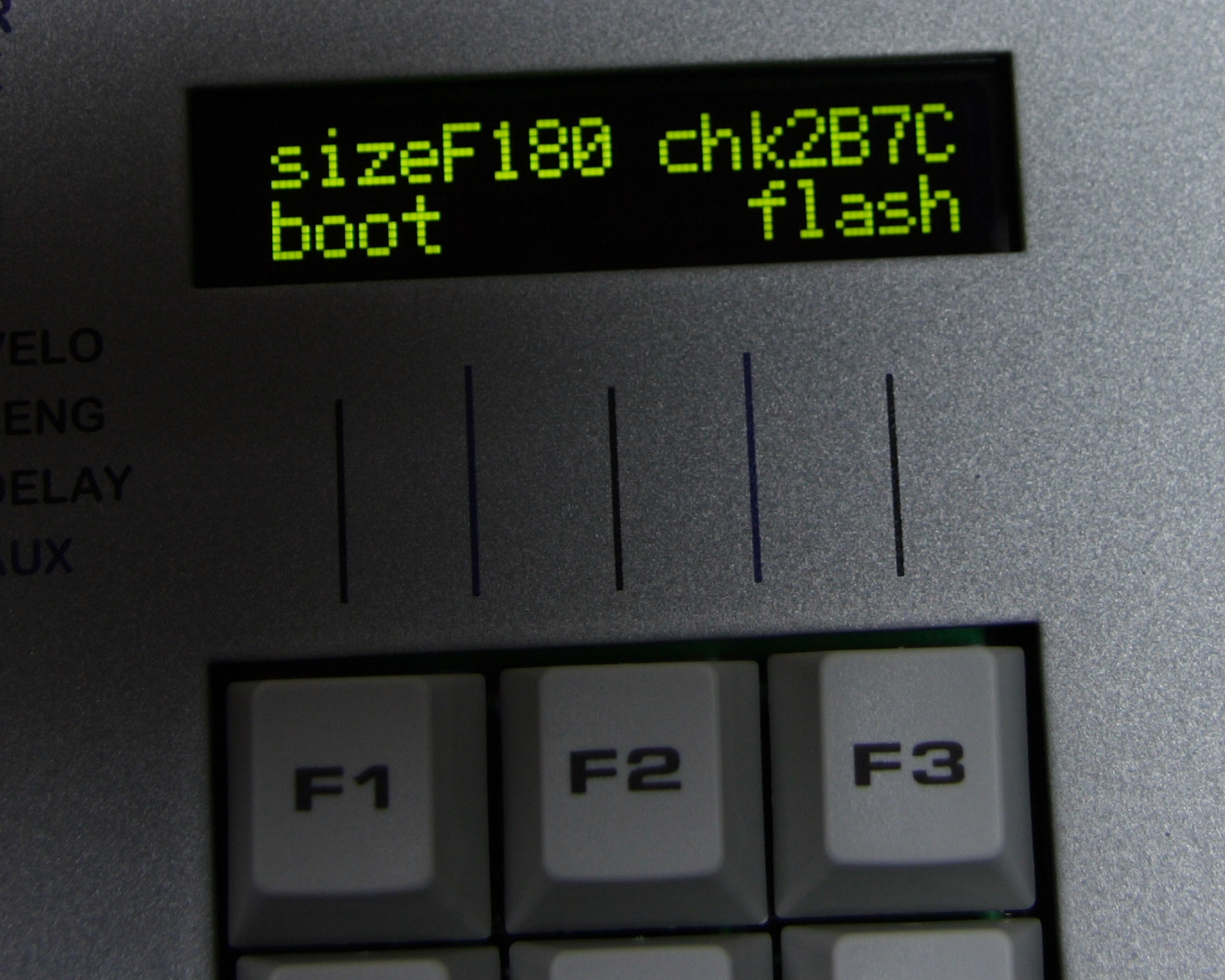
· Firmware update complete, time to boot up with 3.1.006C.
For fuck’s sake. I can’t close the case on the P3.
It turns out that the pots which are recommended for those in the US are sized in a particular way which causes a particular circuit board to stick out far enough that the case won’t close. :\
The other pot option is US$1.35/ea. That’s not bad, except when you figure that I already purcahsed $32 worth of pots and they are now useless. And I can’t finish it this weekend.
I’m going to have to figure out what to do about this tomorrow.


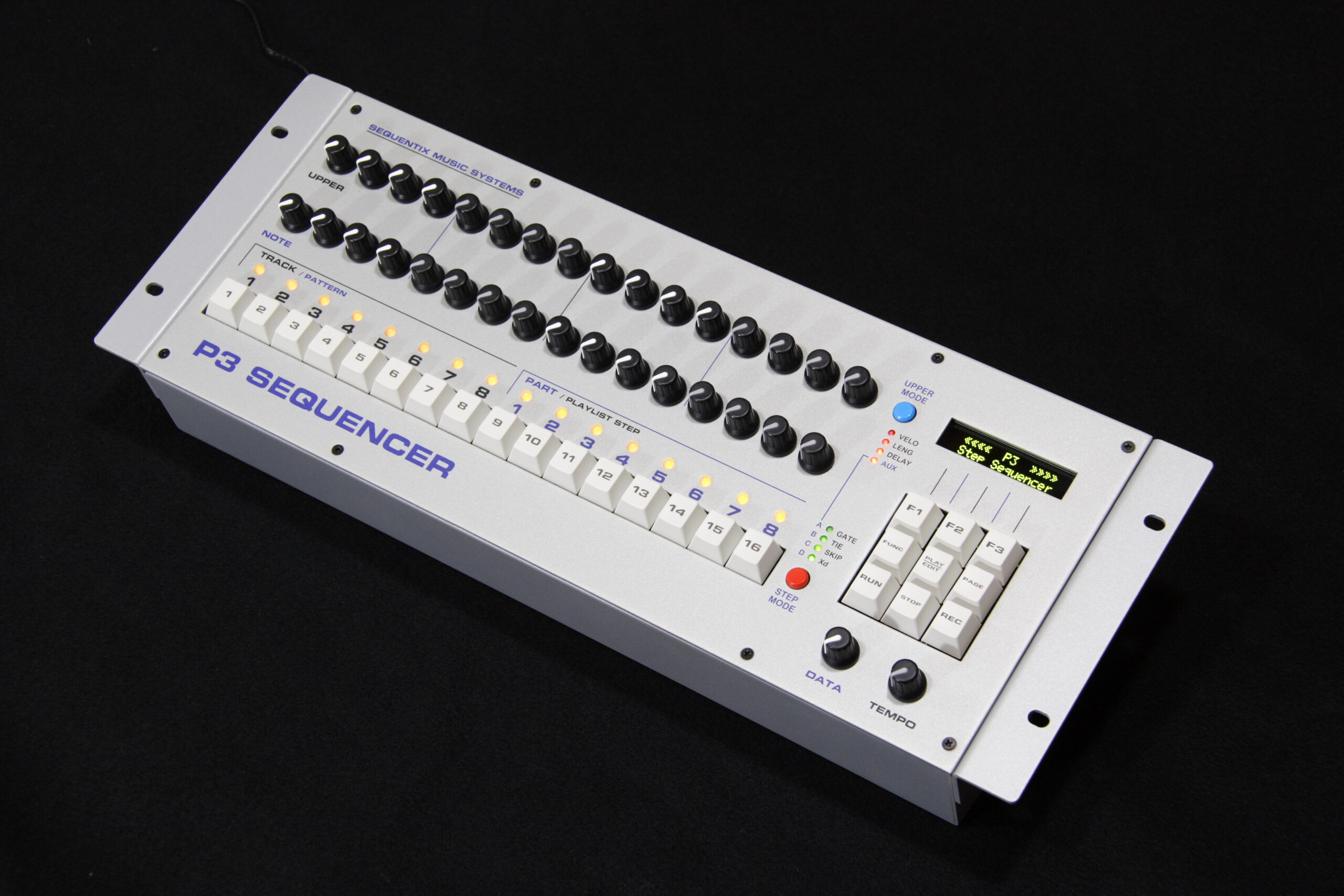
Top of the Sequentix P3 front panel with all modules installed. Knobs are still missing, and the protective film is still over the PLED/OLED.
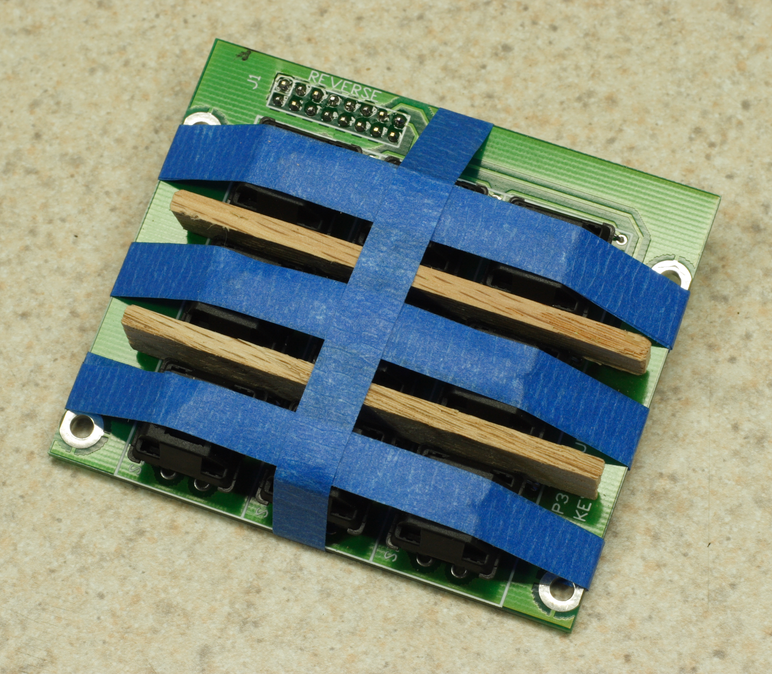
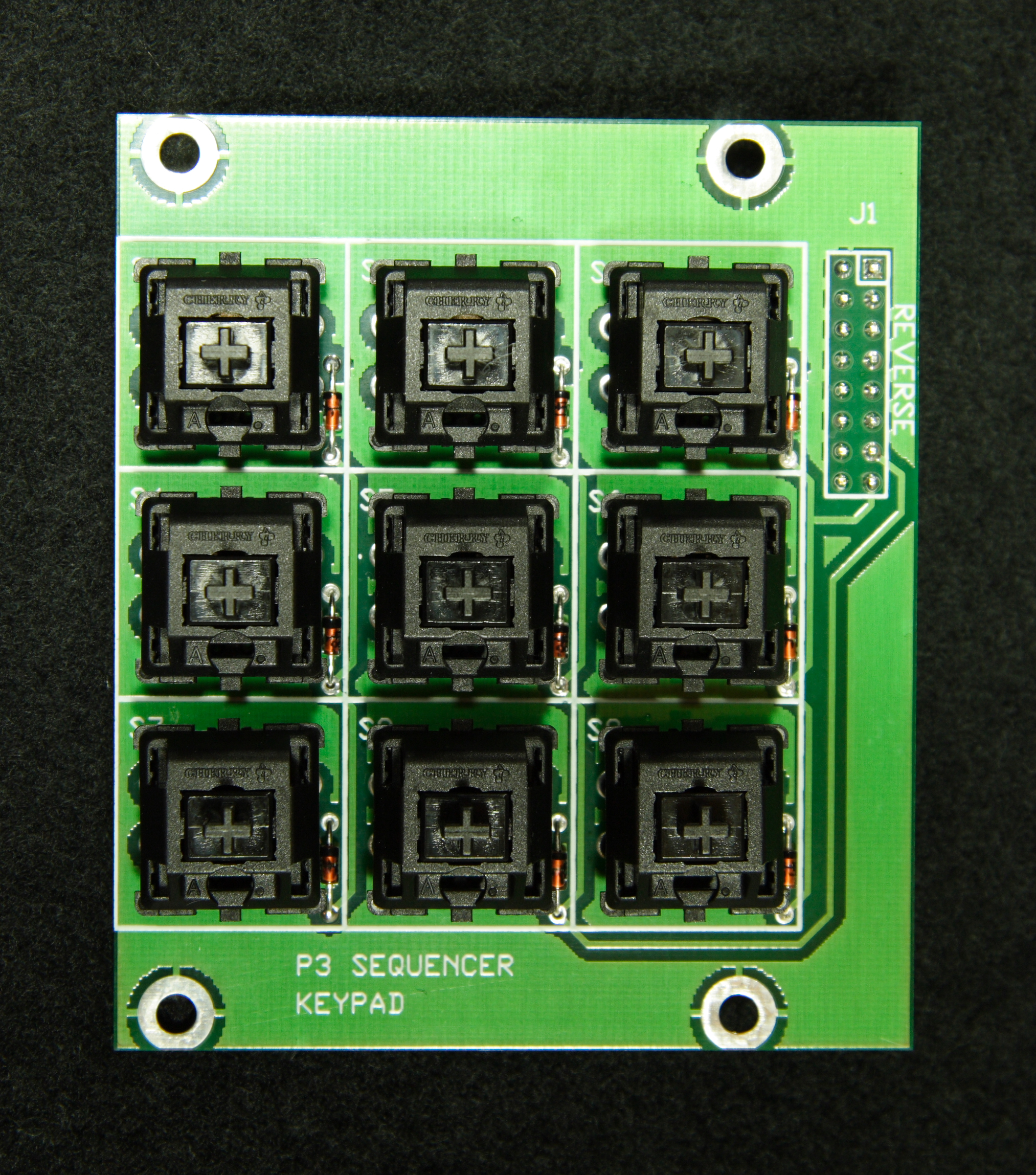
Ah, the Sequentix P3 which I am building (photo gallery retired) is coming along quite nicely. Last night I made a wood and tape jig for aligning the keys on the number pad while soldering them. I think the alignment came out pretty well.
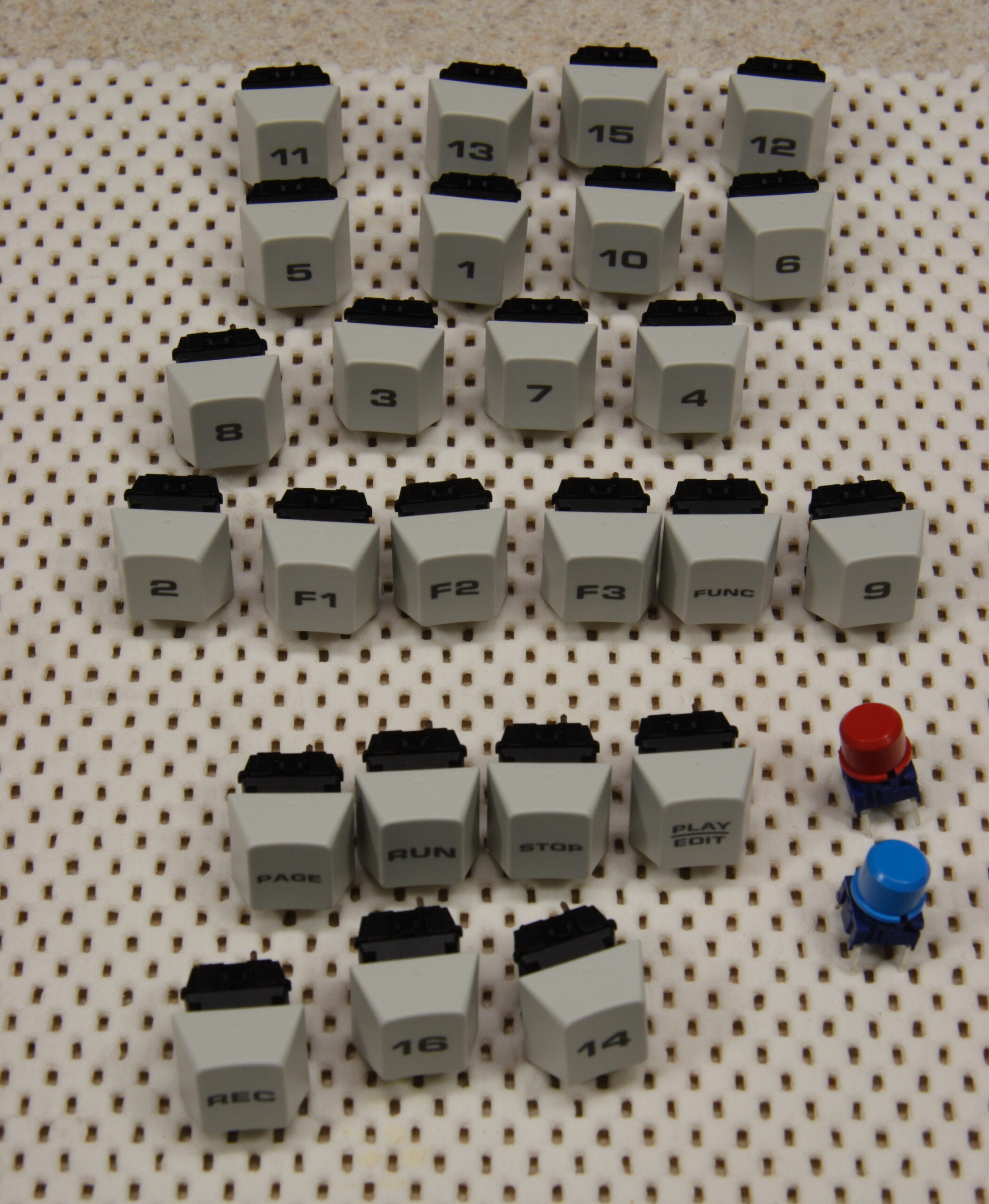
I also spent a lot of time cleaning the remaining flux off of the board and assembled everything in the front panel. It’s all fitting nicely. I can’t believe how nice the Cherry keyswitches and laser etched caps look and feel. They are just perfect, just like an old, quality computer keyboard.
Now I just need to wait for a few ICs to come in from Digi-Key, plug in the chips, and make the cables to connect the boards. :D
I’m getting excited about it.
I just hope it works…
UPDATE: It turns out that the Digi-Key order is being delivered today. I might be able to finish it tonight! (Hrm, I don’t have a mixer… so I can play a bunch of stuff at once, but not listen to it / record it. Oops.)
[Cross posted to

Well, the first order of Casio SK-1 MIDI Mod has been ordered from PCBEX.com. I decided to order from them this time as opposed to PCBFABEXPRESS because there were no listed prohibitions against paneling PCBs nor a maximum average number of holes per square inch. (PCBFABEXPRESS wanted a max of 25, where I was at ~25.24 and couldn’t easily eliminate any more vias.) Hopefully boards from them are decent.
If things go according to plan and the boards actually work, I should have them available for sale as kits within the next couple of weeks. I don’t have final pricing yet, but I expect it to be under US$50 for all parts needed. People will just have to assemble it and put it in their SK-1.
Ahh. I finally took the time to create an entry on my site for info about the x0xb0x.
My goal is to eventually list all the background info on projects which I would normally post just to LiveJournal on the site itself, that way the information is more readily accessable. Hopefully within the next few days I’ll finally get information about the PAiA FatMan Rebuild (aka PAiA FatMan Plus) (photo gallery retired), the iPod installation in my car (photo gallery retired), the iSight Tripod Adapter (photo gallery retired), the cheap lighting rig (photo gallery retired), and maybe a few other things.
Now I’m going to head home and (hopefully) work on the P3 (photo gallery retired) some more, confirm that the board for that Casio SK-1 MIDI input fits in the enclosure, and… oh yeah. Eat dinner.