nuxx.net
Making, baking, and (un-)breaking things in Southeast Michigan.

Category electronics

RS232 to Eaton Leonard Interface Prototype

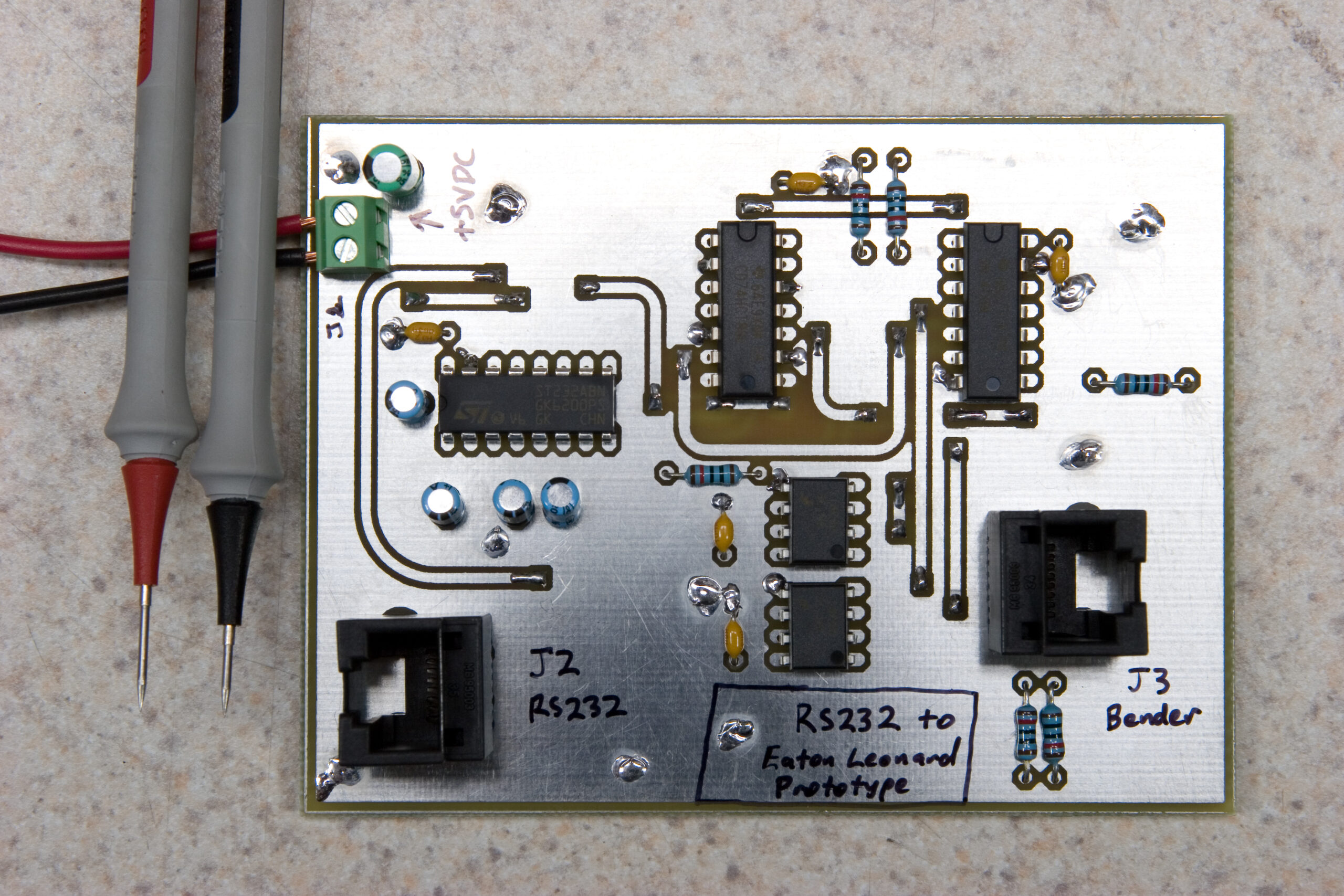
Completed Prototype PCB

Well, after about five hours of working this evening (after laying out the board in free time at work) I’ve finished the prototype PCB for the project I’ve been working on for a friend’s company.

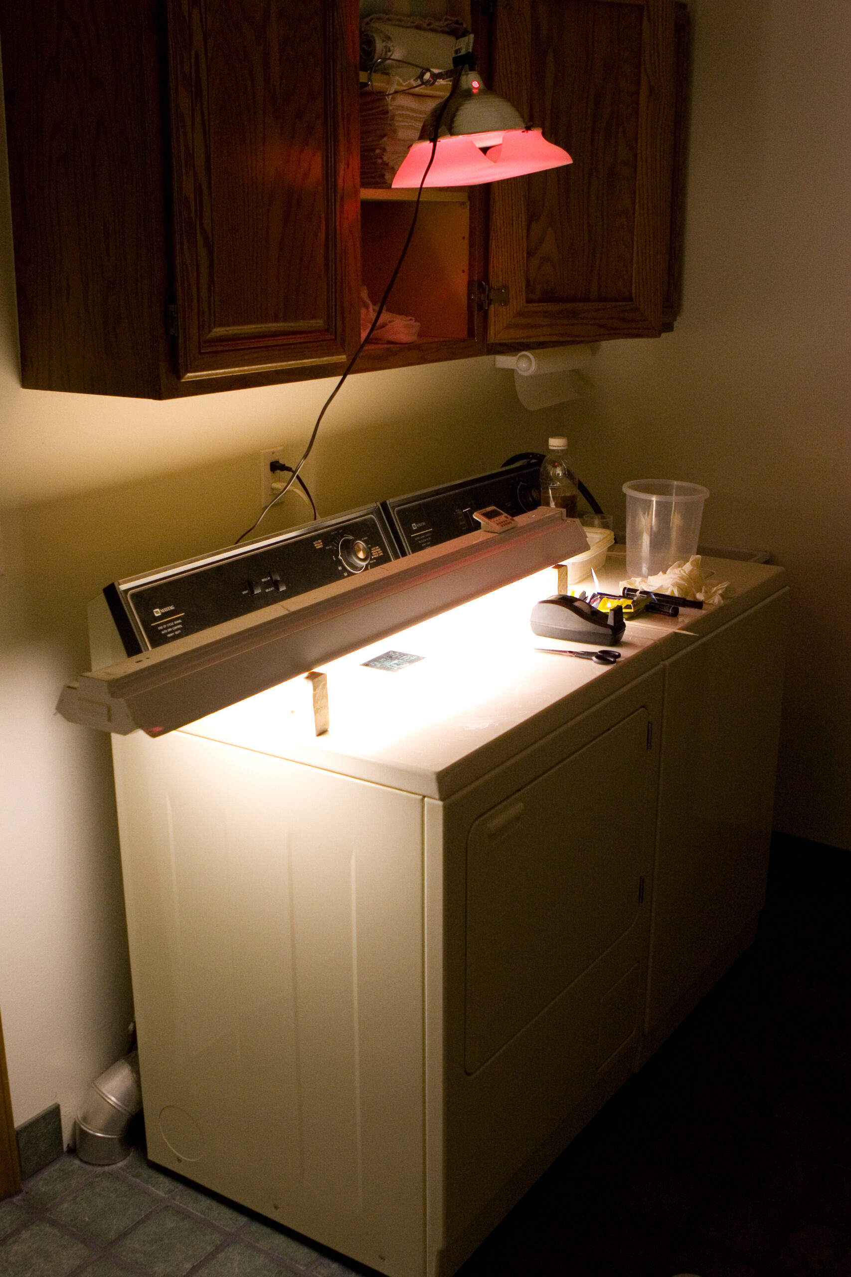
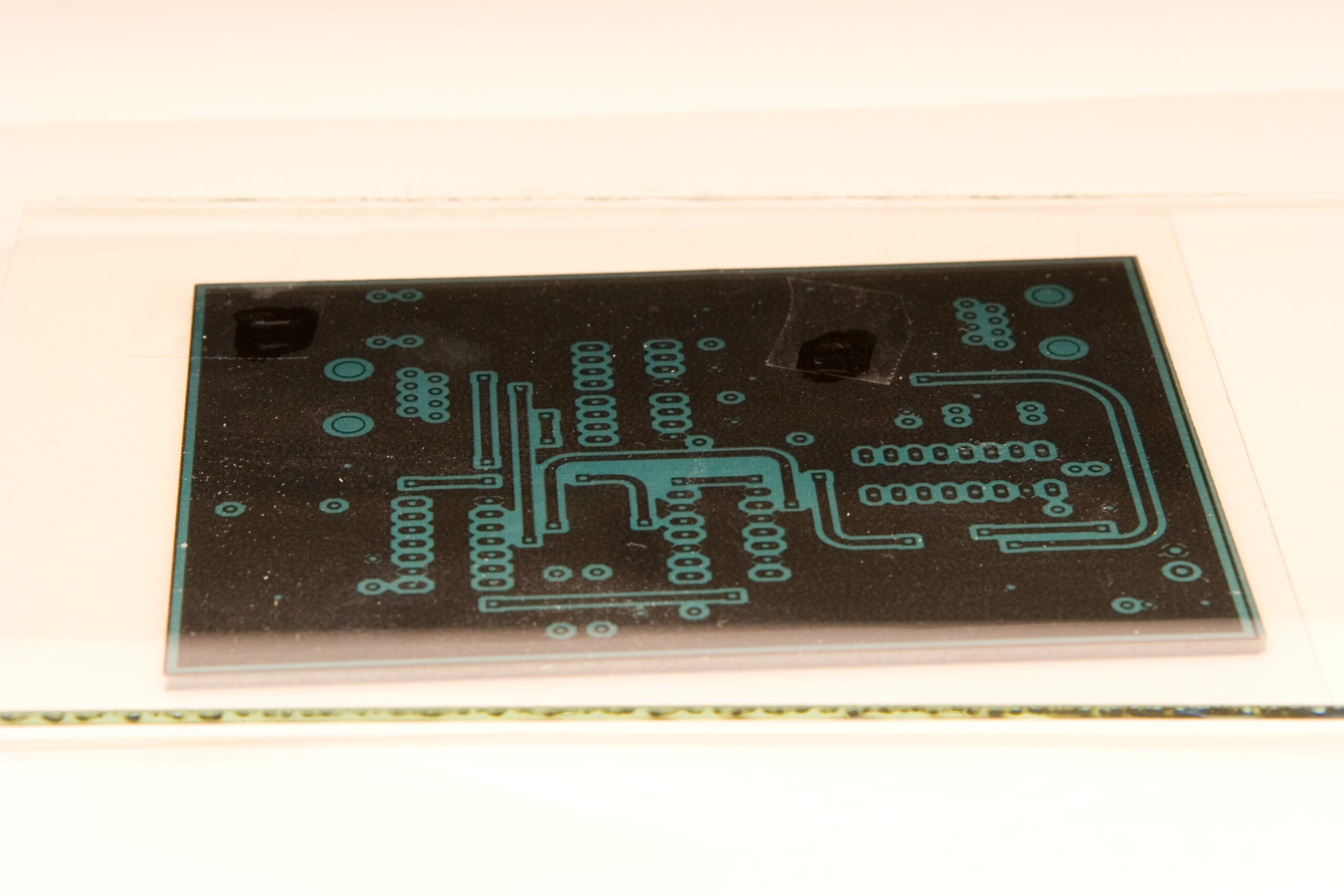
As with the last few boards I’ve done, I etched it in the laundry room, as the laundry tub and large flat surface makes for a good place to work. (Photo of PCB being exposed.)

Then I drilled the board, breaking more PCB drill bits than I like to. Next came manual bridging of vias (which is a really awful chore), and then finally assembly. After I had it put together I powered it up, probed around for shorts, and generally confirmed that it wouldn’t explode.

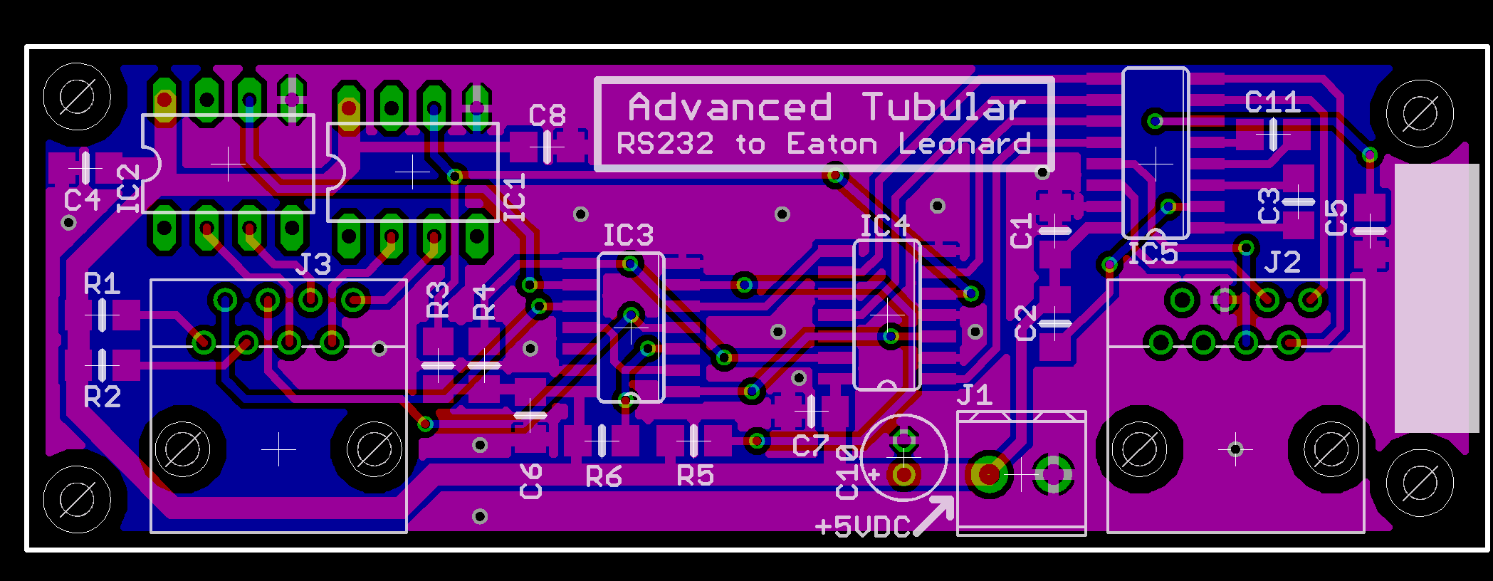
Tomorrow I’ll confirm that the pinout of the board is as expected, and hopefully I’ll be able to deliver it at lunch time. If it works I’ll (hopefully) have some production boards made for them. I stayed late at work avoiding traffic and worked up a first draft of a mostly-SMT board layout, fitting in ~30mm x ~85mm. If I end up producing these boards I can see the final product being something like this, should I choose to do it SMT.

Hopefully tomorrow I’ll get to unpack the new baking stone, the new x0xb0x kit, and maybe just relax a bit. For now it’s bed time. Goodnight.

electronicsmaking thingsmoved from livejournal

HMLiberator Assembled

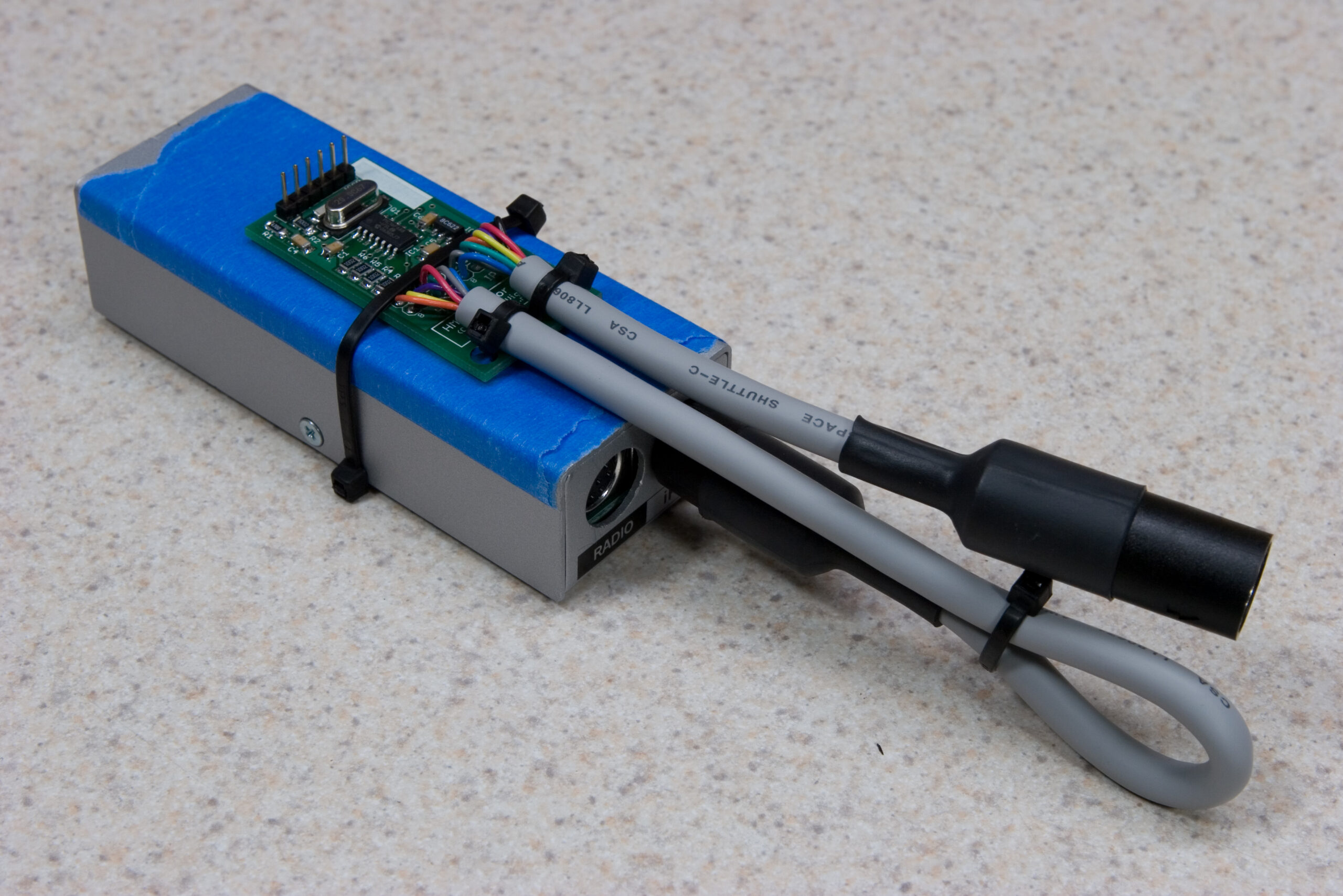
First HMLiberator Assembly with Honda Music Link

Well, there’s an assembled version of the first HMLiberator, strapped to the top of a Honda Music Link. This is very similar to what the final assembly will look like, except the ISCP connector will not be soldered on, the part will be encased in shrink tubing, and there will likely be slightly different cable / connectors used.

I still have a good ways to go on the software. If connected it’s possible to use all controls on the iPod to play music and hear it through the stereo (the initial goal), but I still have to address the following things:

· iPod does not pause / power off when vehicle is powered off.
· HML continues charging iPod while vehicle is powered off. (HML’s software is hanging and not cutting power to the iPod.)
· Attempting to change track on the head unit hangs the HML. (I think it’s not getting the response it desires.)

I think most of these are just a matter of getting the false polling mode, track change responses, and things like that working. After I get back from up north (and get the serial level converter prototype made) I’ll put together another serial sniffer and get back to work on the software.

automotiveelectronicsmoved from livejournal

HMLibeartor v1.0 PCBs Have Arrived

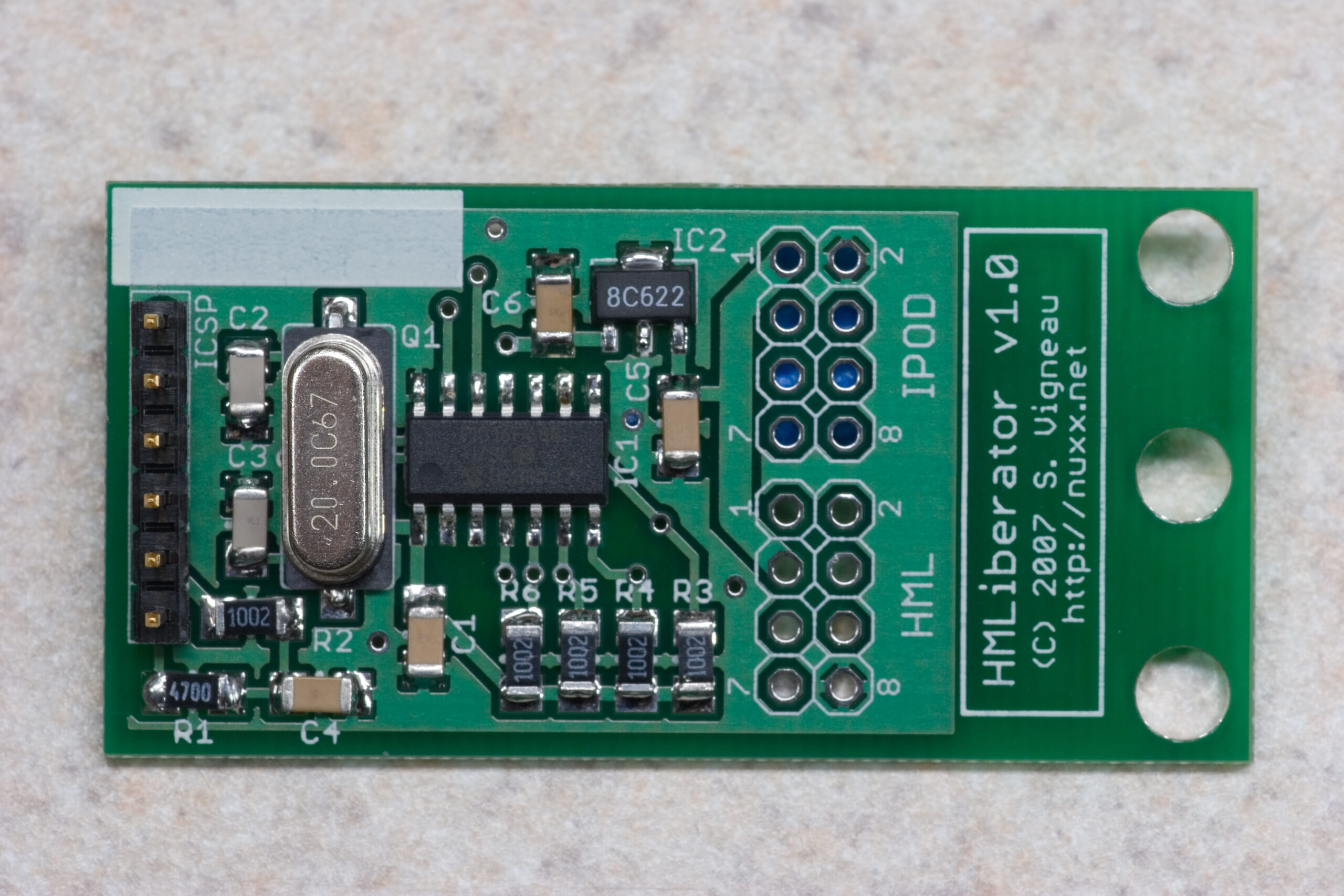
HMLiberator v1.0 PCB complete, except for cables.

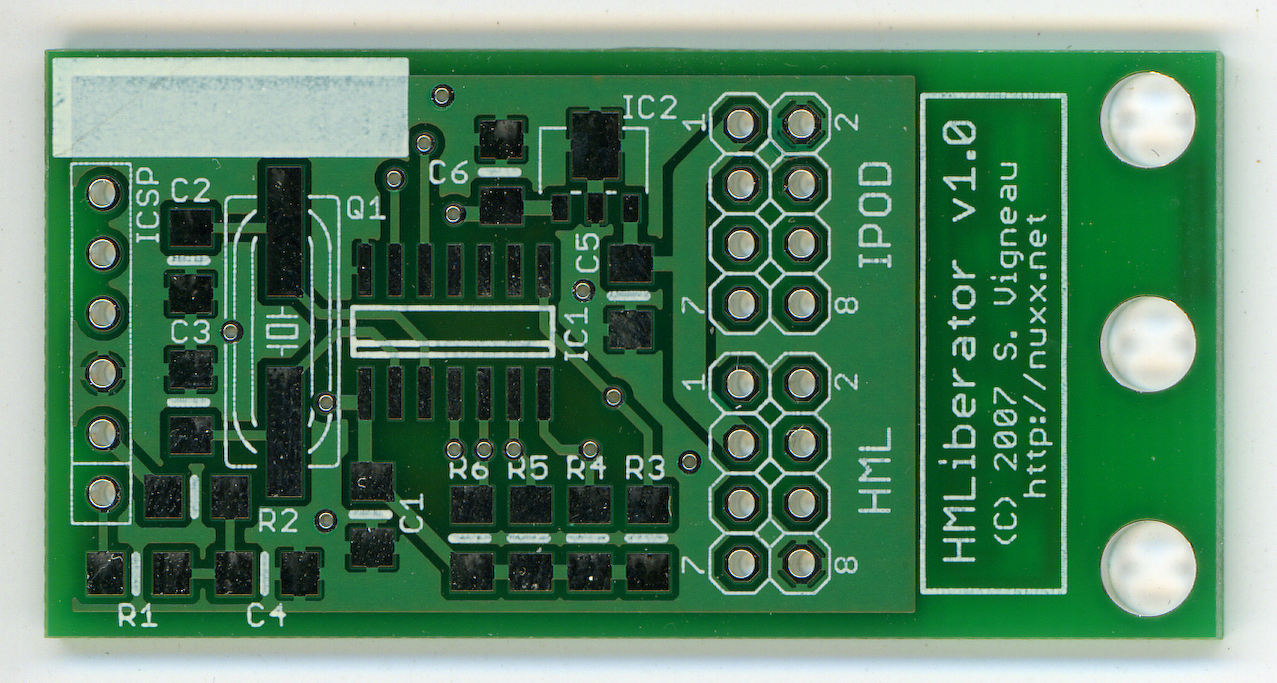
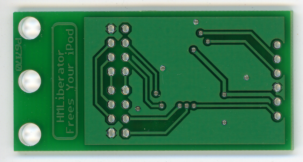
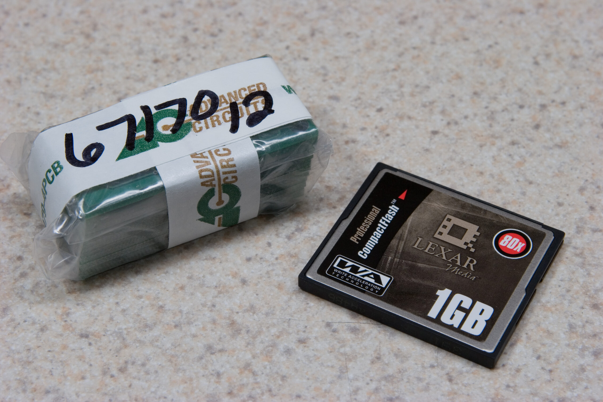
Well, the HMLiberator v1.0 PCBs arrived today from Advanced Circuits. (Top and Bottom at 600dpi.) They came in a rather large box which can be seen in the photo in this post. The size of the box seemed to matter, though, as not only did it contain the wrapped stack of PCBs, it also contained a t-shirt, sticky notes, and a bag of microwave popcorn.

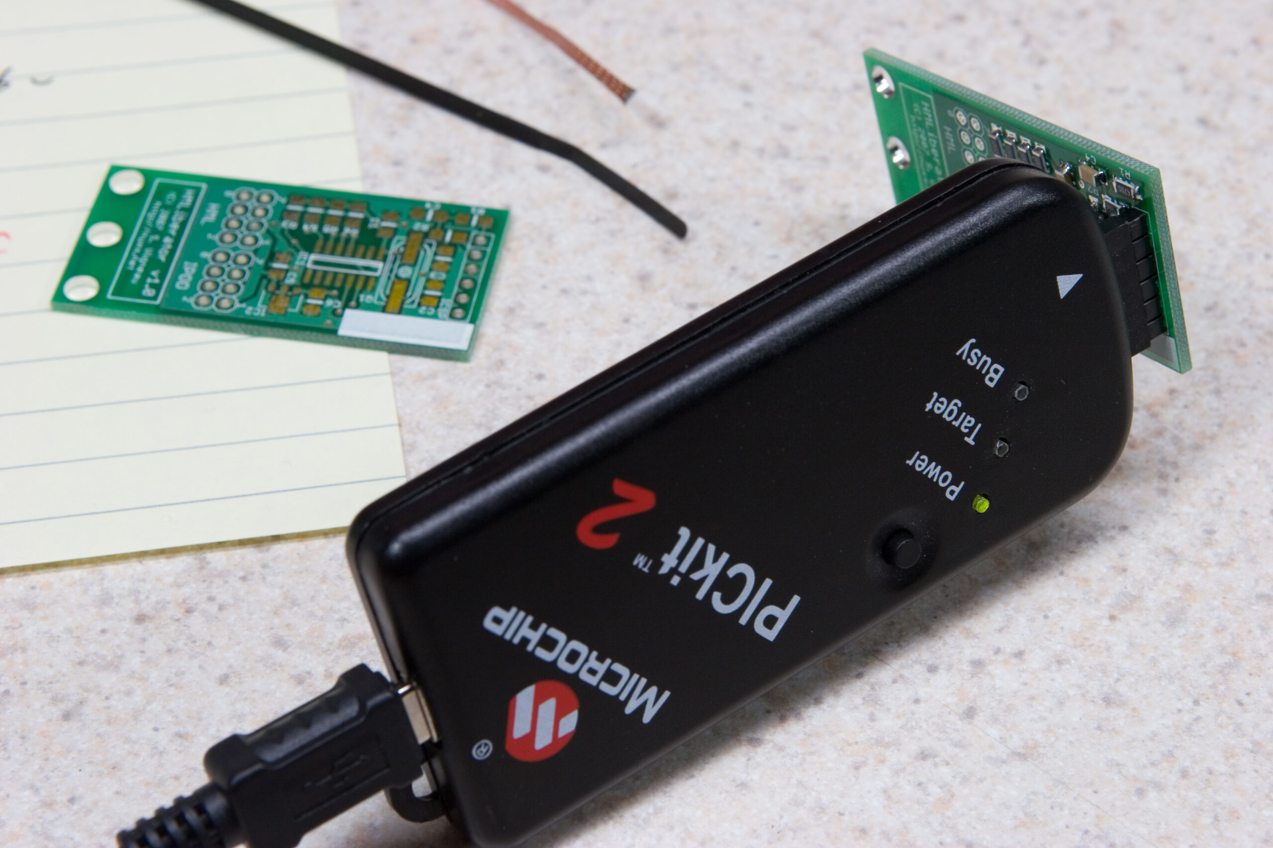
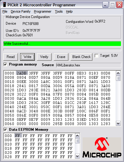
I got the first board fully assembled, with the SMT stuff taking a bit longer than normal, although I found that it wasn’t too bad. Things must have gone at least partially right because once I connected the programer to do a test-write with some random copy of the firmware it wrote successfully.

Since Danielle just got here we’re going to grab food and watch a movie. Tomorrow I’ll test the voltage regulator, add the header cables, and connect it to the car for the first time. Hopefully it’ll work. :)

automotiveelectronicsmaking thingsmoved from livejournal

My Office

(Cross posted from YakYak…)


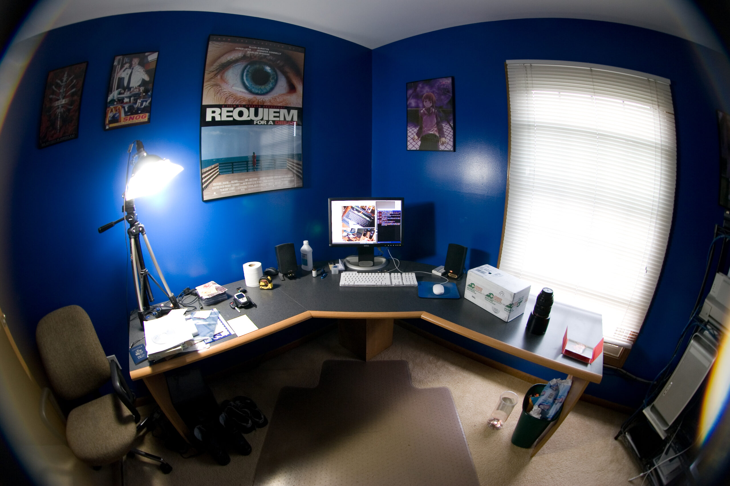
Here’s my desk / office at home taken with an 8mm fisheye lens. You can just barely see the door and G5, which are in opposite corners of a 12′ x 12′ room.

That’s exactly how it is now, except I’ve opened the just-received-before-photo box from Advanced Circuits. (They are the prototype PCBs for a project I’m working on.)

Click on the image to make it full size…

(And please ignore all the wacky flare. It is a fisheye with a 47W diffused daylight CF near the edge.)

around the houseelectronicsmoved from livejournal

Electronics Help: Current Loop

Staying late at work today I set about turning this PCB into this schematic. (I also replaced the MC1488 / MC1489 combo with a MAX232, eliminating the need for a bunch of diodes and feeding the board +/-15VDC.)

It supposedly turns RS232 into current loop, where amperage is used to signal 0 or 1 instead of voltage. This makes the signal more robust in noisy environments or with long wire runs.

The thing is, when I look at this, I can’t quite see it as being anything more than a device which takes RS232 serial and converts it to be 0V or 30V (for low or high), and optically isolates data going back to the PC. I don’t see any way it actually varies the amperage while keeping the voltage steady.

Can someone correct me, or confirm what I’m seeing? The schematic, as made from the board, is here.

(Also, I need to remove the 7486 part. Each currently grounded leg of the gate was originally set to a jumper to select if it should be high or low, but the needs of this board are fine having them all grounded. As it’s XOR on all of them, and one leg is always pulled low, the output will always be whatever the input is. So, I think I can eliminate the 7486. I believe the jumpers serve to invert the signal, should it be needed. But it’s not. And I didn’t remove the 7486 while removing the jumpers because I wasn’t certain of it was used for anothing else. But now I know. And knowing is half the battle.)

electronicsmoved from livejournal

x0xb0x

It seems that I’m now able to order another x0xb0x kit. So, I shall. This one is more of an investment, though… Something easy / fun to build which I can slap my remaining piece of custom artwork on and sell on eBay. Or something. :)

It’ll be about $360 total, but I think it’ll be worth it…

acquired thingselectronicsmoved from livejournal

HMLiberator v1.0 PCBs Ordered

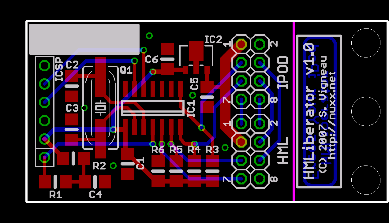
HMLiberator PCB v1.0HMLiberator PCB v1.0
(Click for 600dpi version.)

Well, it’s done. I’ve ordered the first run of PCBs for the HMLiberator. While they are technically a prototype, these v1.0 PCBs should be also be usable as the final part. The circuit is pretty simple, and I’ve checked things over a number of times, and it all seems right. Now I just need to finish the software.

Thanks to Advanced Circuit’s $500 Free Promotion I was able to get a $500 credit towards one or two orders, making this entire order free. I’ve heard excellent things about Advanced Circuits, and due to the small tolerances on these boards I wanted to be sure they’d be done right. Also, should I go production on this item, 250 boards will only cost $1.94 each.

For now I ordered 12 boards, as any quantity from 5 to 12 were the same total price (price per board * quantity). With any luck I’ll have them by the weekend, or maybe early next week. Until then I can just finish polishing the software.

If you are interested, the schematic is available in black and white or color. I’ve also uploaded another file containing the Gerbers and CADsoft EAGLE files, should anyone be interested in them.

Now, to get back to normal work, and possibly update the online documentation for the project a bit later. I also should make a post about Saturday, which was a really nice day of beer brewing, friends, and beer in the evening. (Although I think a bit too much beer… or maybe too much Mt. Gay afterwards at ‘s place.)

electronicsmaking thingsmoved from livejournal

OPPO DV-970HD

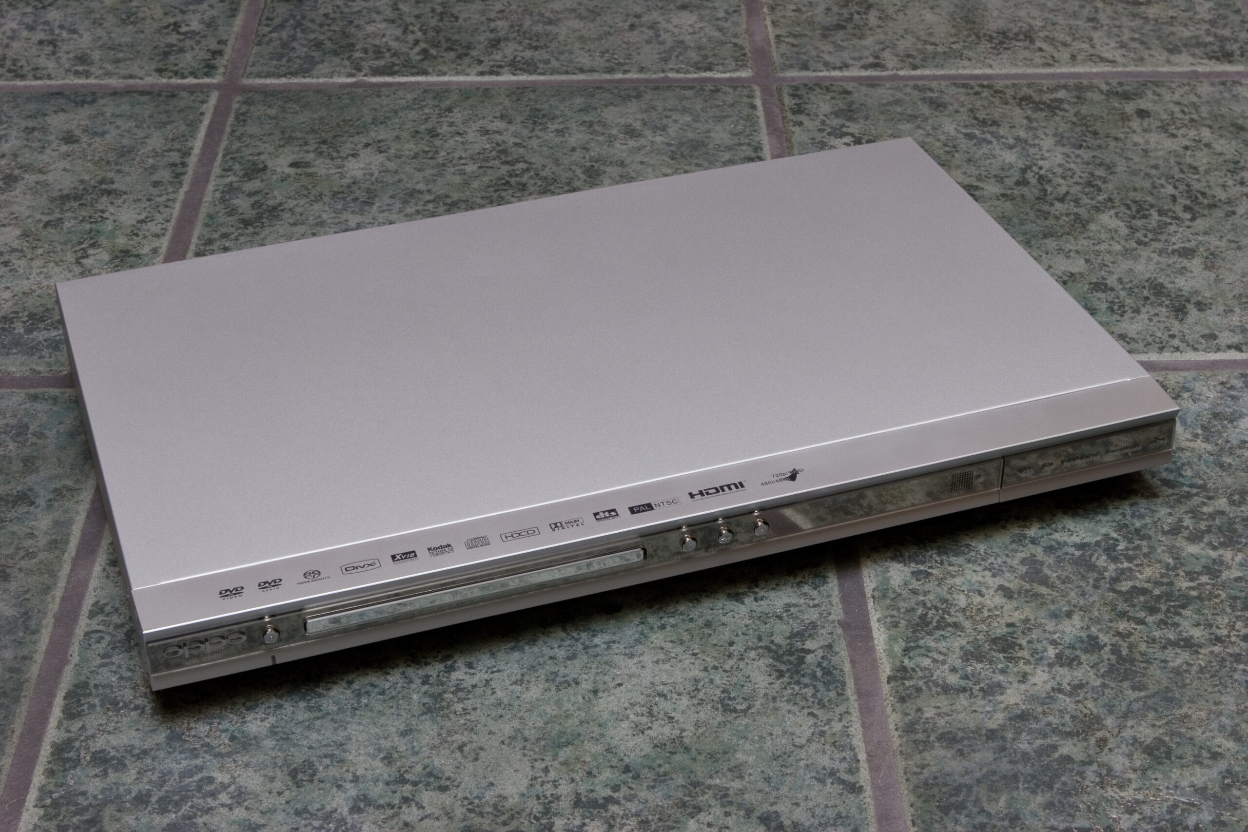
OPPO DV-970HD Upconverting HDMI DVD (and more) Player

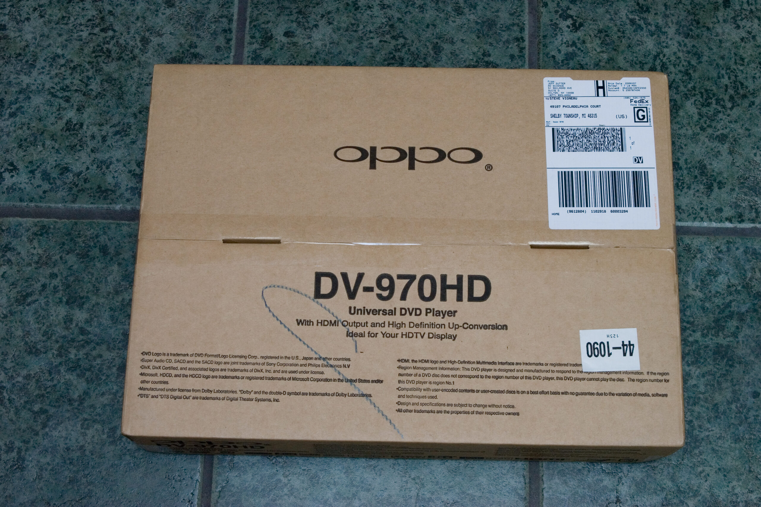
Yesterday while and were over here for birthday things, the FedEx driver left my new DVD player in the garage so quietly I didn’t even hear the truck drive up. Because of yesterday’s activities I put off unboxing and setting up the player until today.

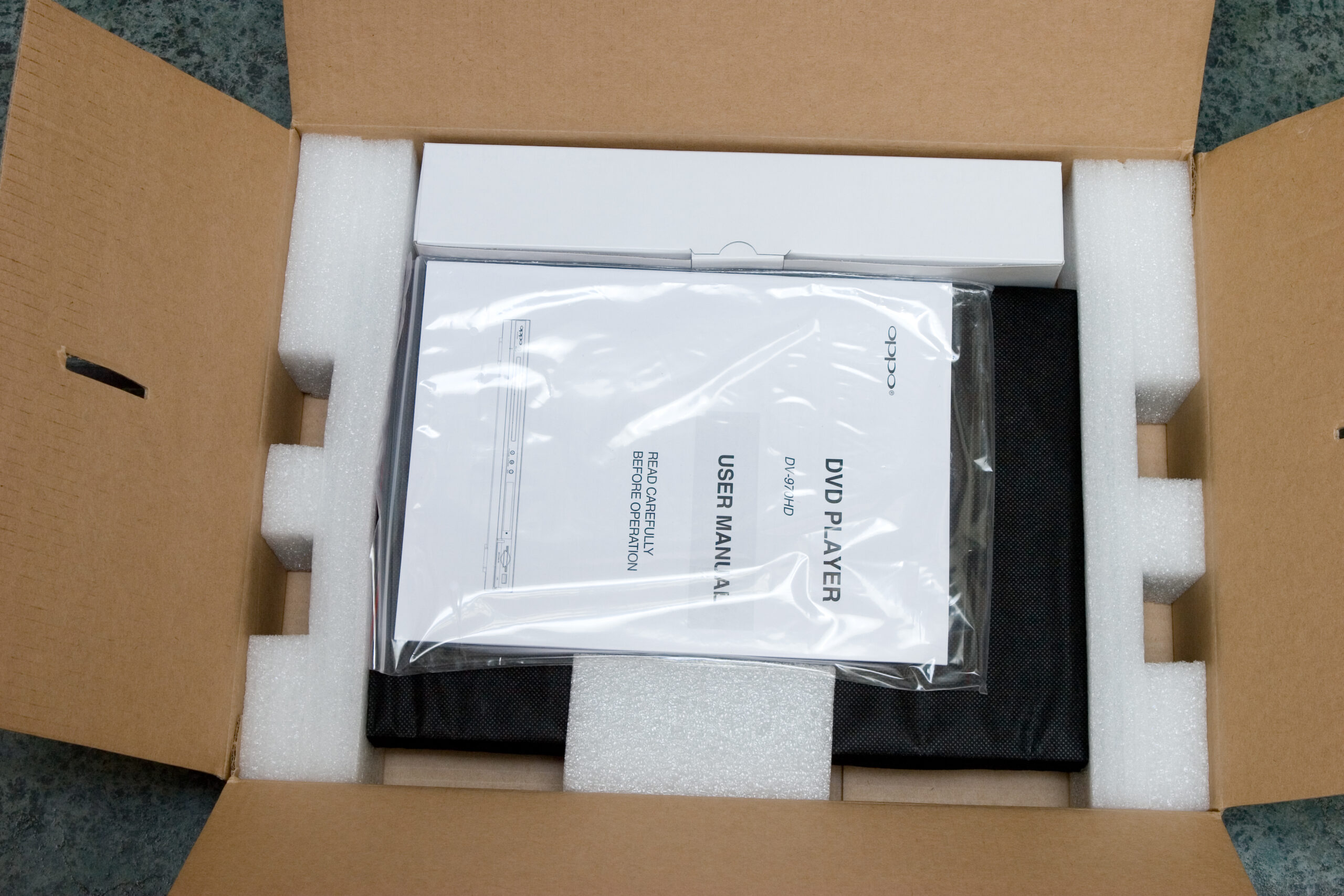
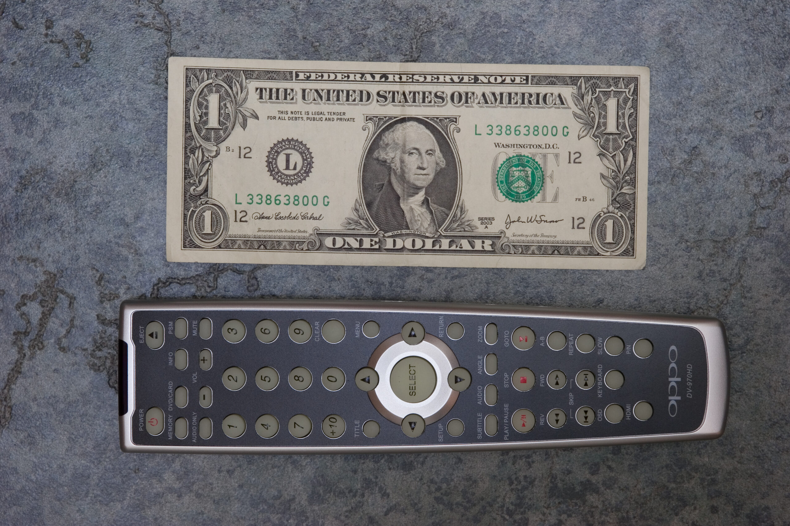
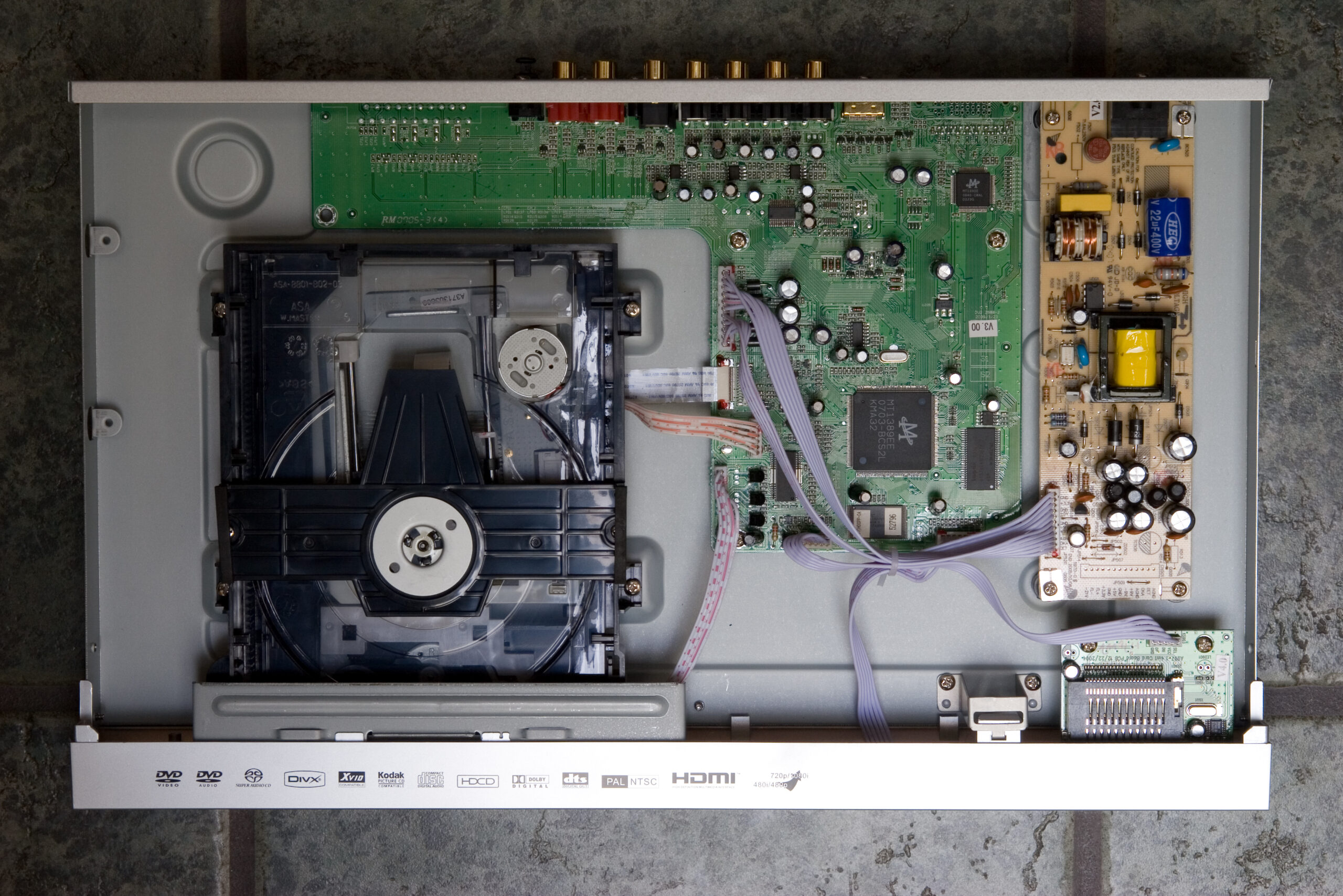
Well, as part of setting it up I took a number of photos of the unboxing of the player, the inside of it, etc. While deciding if I wanted to purchase the player I couldn’t find any good photos of the player, the remote, things like that. Since I normally find photos like this useful, I decided to take some in hope that others would find them useful.

First, I found out that AV Science is selling the players for US$149, plus $10 for FedEx shipping. While the players are available with free shipping via Amazon, I didn’t want to wait the typical two weeks that it takes for free shipping items to arrive.

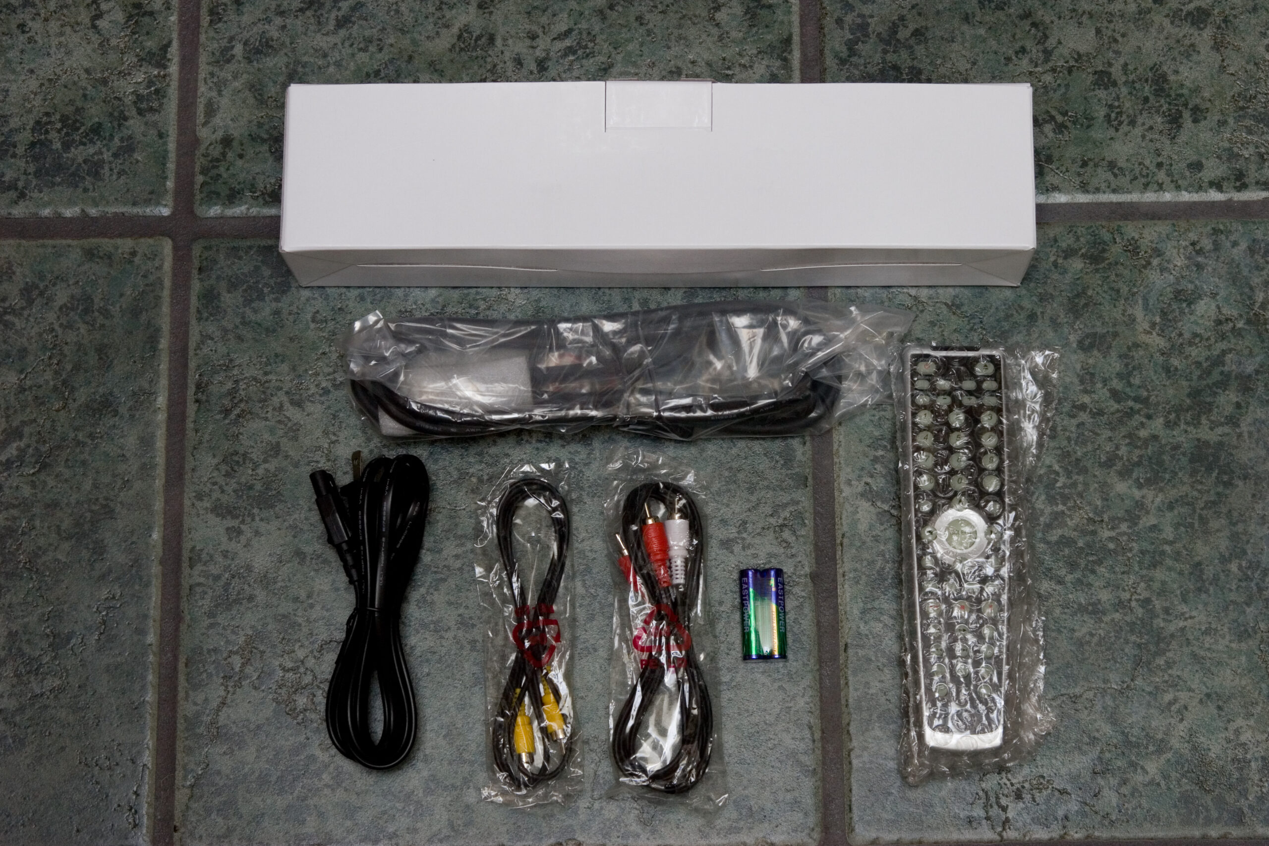
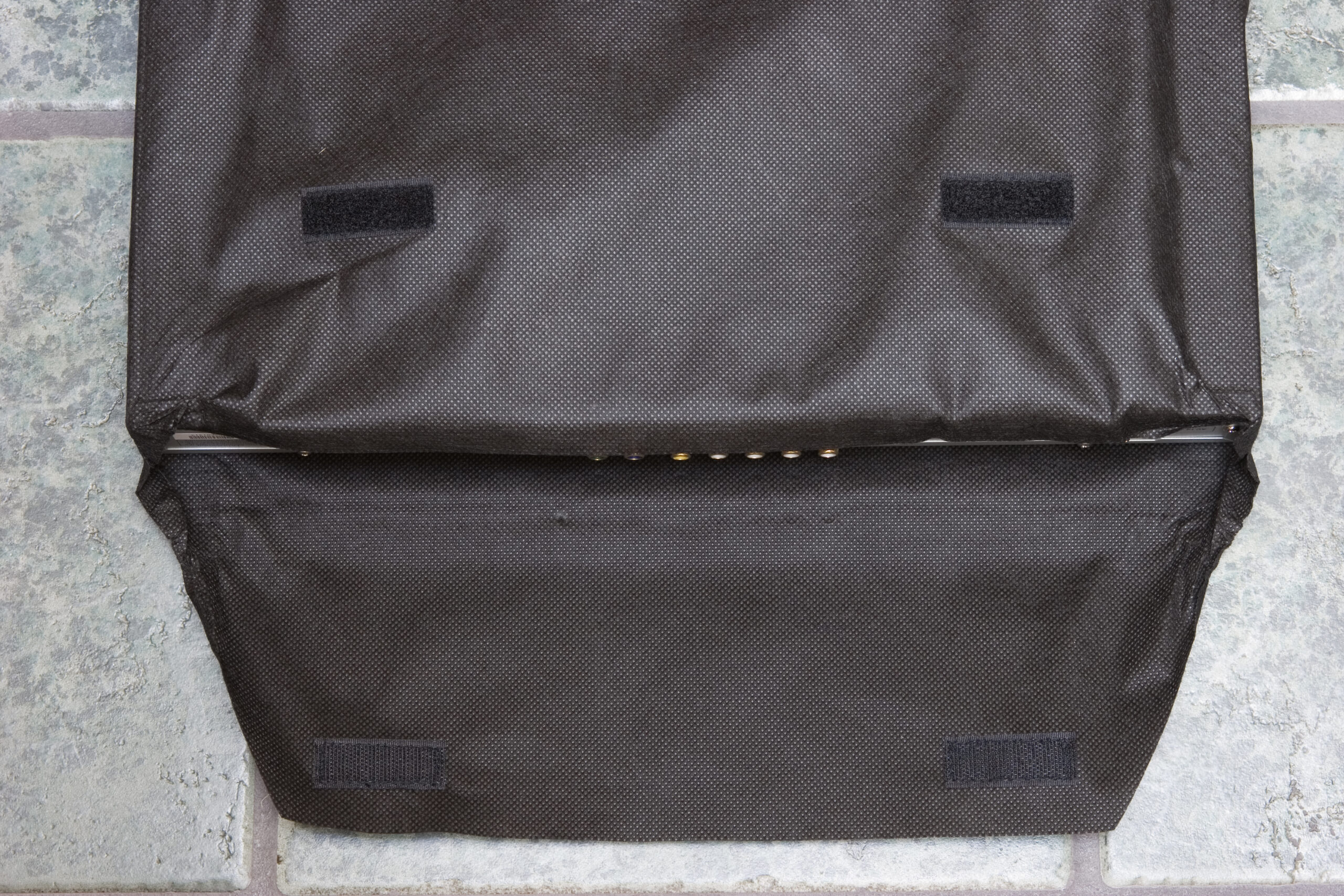
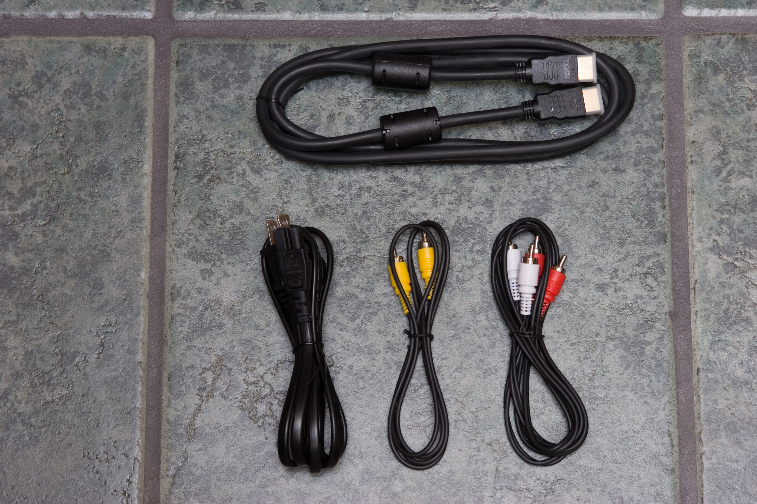
The player arrived in a brown cardboard box. The box looked like it had been dropped on the corner a few times, but opening the box showed enough packing material that this was not a concern at all. Inside the box was the instruction manuals, a box containing the cables and remote, and the OPPO DV-970HD player itself, in a black cloth bag similar to what iPods ship in. (Strangely, this bag has hook and loop fastener closures.)

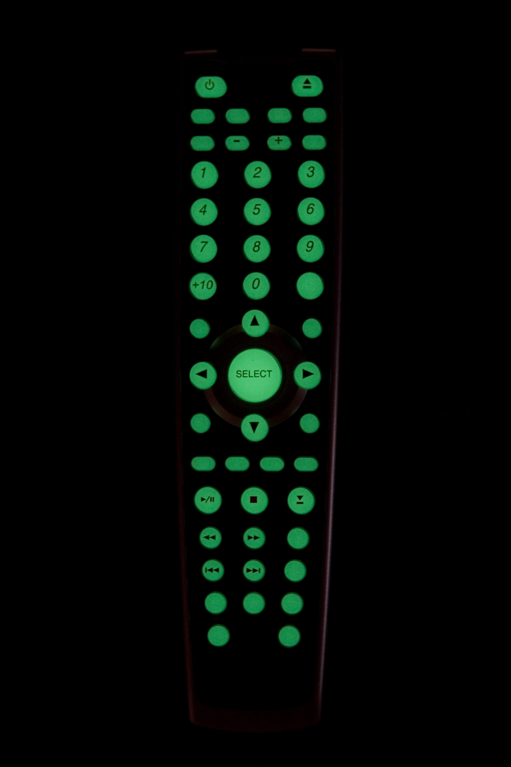
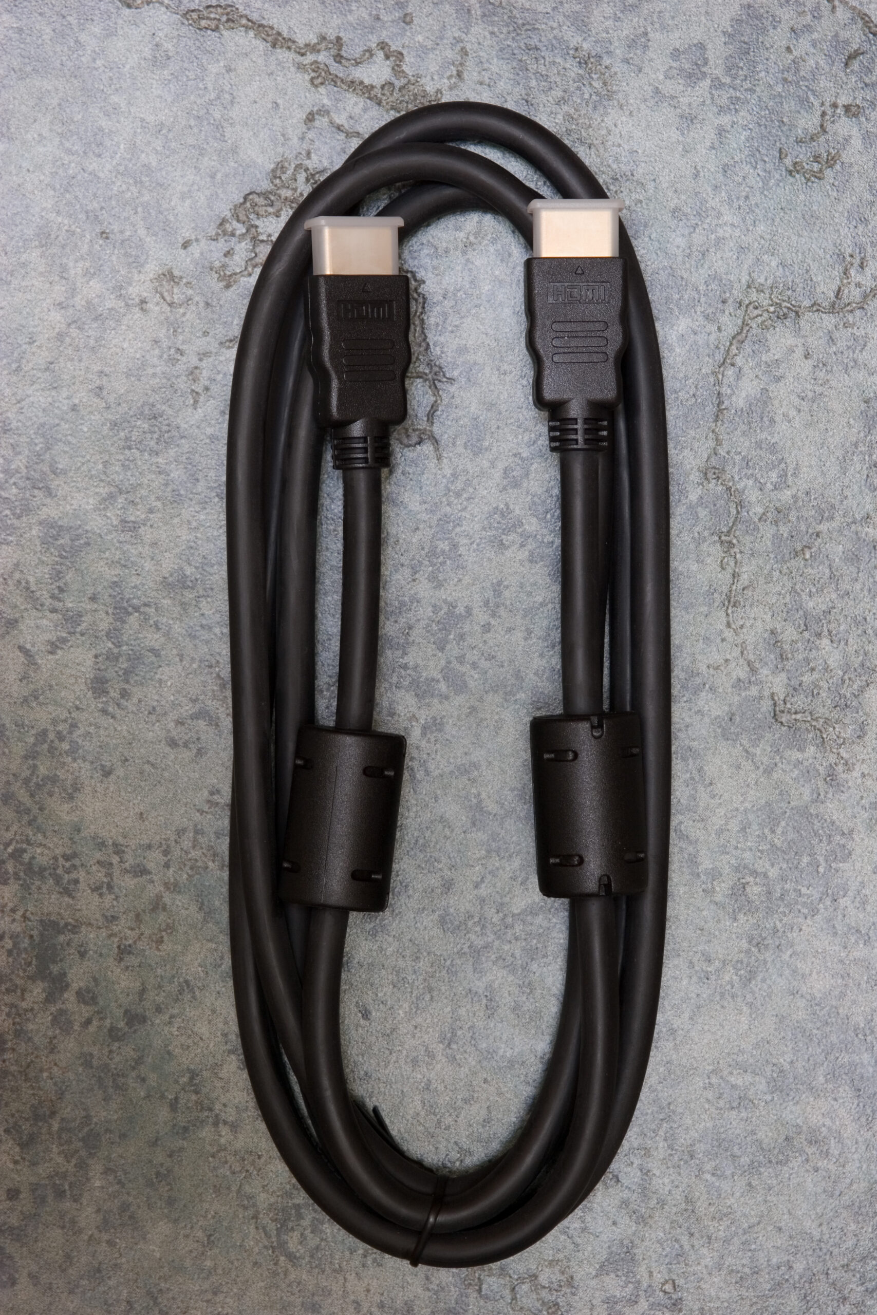
The remote is nicely sized and contains all the needed buttons, and also glows in the dark. Somewhat unlike most other players I’ve come across, the OPPO HD-970HD comes with a rather nice HDMI cable. (I’m using this cable, because initial testing has shown that allowing the player to upscale DVDs to 1080i looks best on my TV.) There are also a couple of audio cables in the package, but I’m not using either of those. Thankfully the player as a TOSLINK connector on the back, so I’m able to use that, just as I was with my old Sony S550D. (Rear view of player.)

This player also plays SACD, and (due to stupid restrictions on SACD) outputs the audio to the on-board 5.1 connectors. I still have to make cables to go between that and my receiver, but it’ll be nifty to give some of the surround sound discs a listen. (The player will also downsample / downmix them to stereo for digital output.) DivX support seems pretty good, although the only files I’ve tried playing are test encodings as part of the DivX TestCD v2.0.

One rather nifty thing about this player is that it’ll play supported media from either flash drives or USB v1.1 mass storage devices via the front panel card reader / USB connector.

I currently only have one complaint about it, and that’s regarding the brightness of the LED display on the front panel of the player. To put it simply, it’s brighter than anything else near my TV. I might look into either changing the resistors to dim it or simply unplugging it, but I’m not sure yet.

That all said, and while I haven’t taken the time to calibrate everything against the TV (the whites seem a bit blown out, as some things were trailing on the screen while watching test discs) the image quality seems to be quite good thus far. DVDs look loads better than they did with either my old player or any of the low-cost ones I’d tried last week. Thus far, I’d definitely recommend getting this player, and with the really prompt shipping from AV Science I’d suggest getting it from them. Being a custom AV shop they don’t do online orders, but if you call them up they’ll do the order that way. (I think they aren’t normally a single-item online retailer, but they are selling these…)

If you’d like to see more pictures of the player and such, including inside of the player, here is my OPPO DV-970HD unpacking gallery (photo gallery retired). OPPO’s site with more info on the player is here, and a huge thread about it at the AVScience Forums is here.

Now, it’s time for Danielle and I to go get some Thai food and just relax.

(By the way, if you enter setup on this player and press 9210 on the remote, a screen indicating the current region is displayed. Pressing a new region code, such as 0 for all, will change the region code.)
acquired thingselectronicsmoved from livejournal

SMT Parts

Crystal, PIC, and voltage regulator on a laser printout of the HMLiberator
(Click for full size image.)

The first batch of board-level parts for the HMLiberator came in today. It’s enough parts for three devices, with a few extra SMT parts thrown in just in case I drop them, sneeze, whatever.

That up above there is a laser printout of the latest board layout with the electronics filling a 37mm x 25mm area. I’m going to redo the pinout of the cables to make routing of traces more efficient, but that shouldn’t affect the other areas. Also, as you can see, the part footprints are good. So, barring any manufacturing problems, it should work out great.

I took some more macro photos (true macros) of other SMT parts received today, because I thought some people reading this might be interested to see them:

· Four size 1206 SMT .33μF 25V capacitors sitting on a dime. These are Mouser part 77-VJ12Y25V334K.
· One of the .33μF size 1206 capacitors sitting on the PCB printout.
· Surface mount parts in cut tape packaging.

electronicsmaking thingsmoved from livejournal