nuxx.net
Making, baking, and (un-)breaking things in Southeast Michigan.

Category electronics

IC Sorting

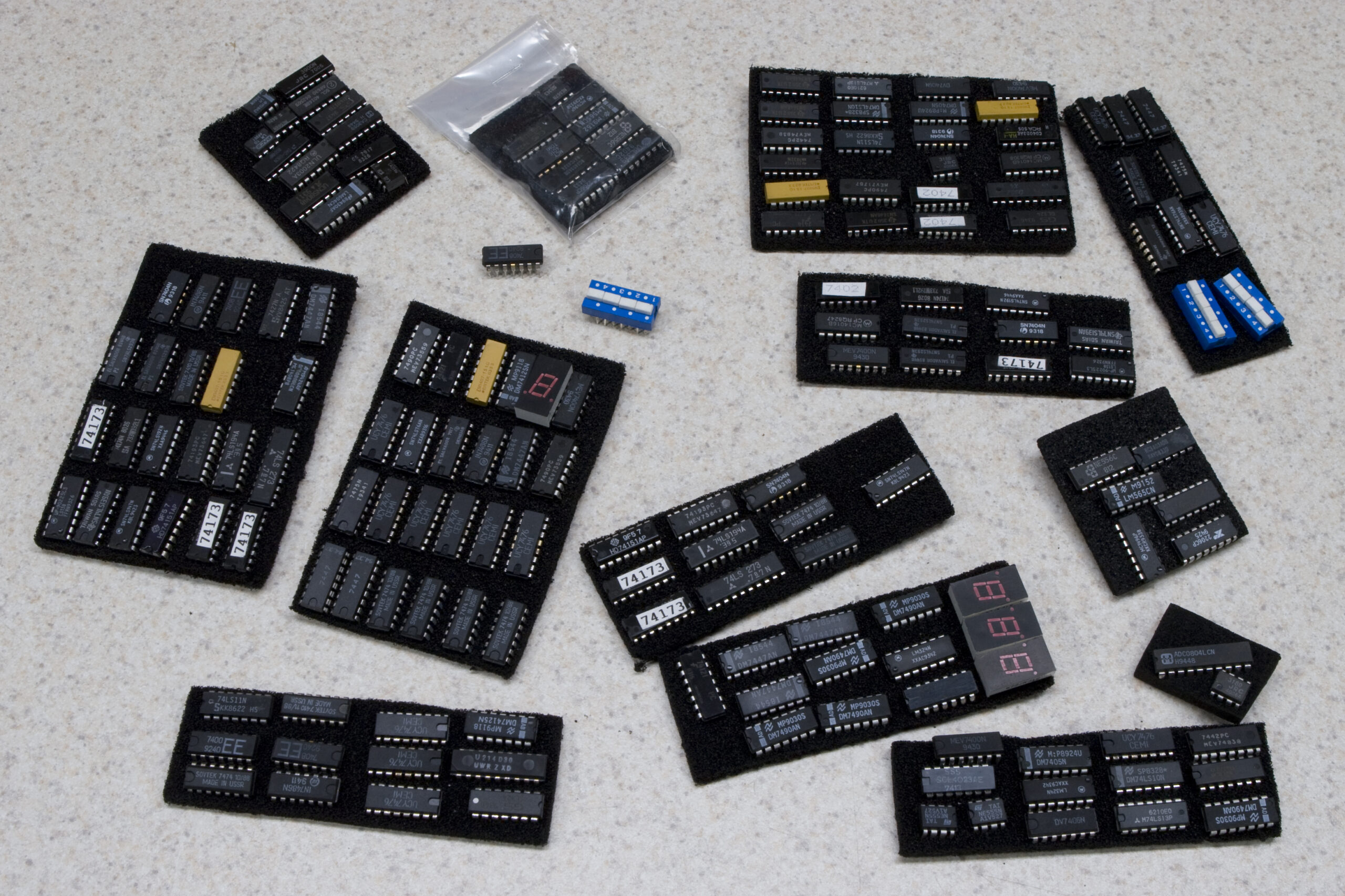
Sorted ICs
(Click for higher resolution image…)

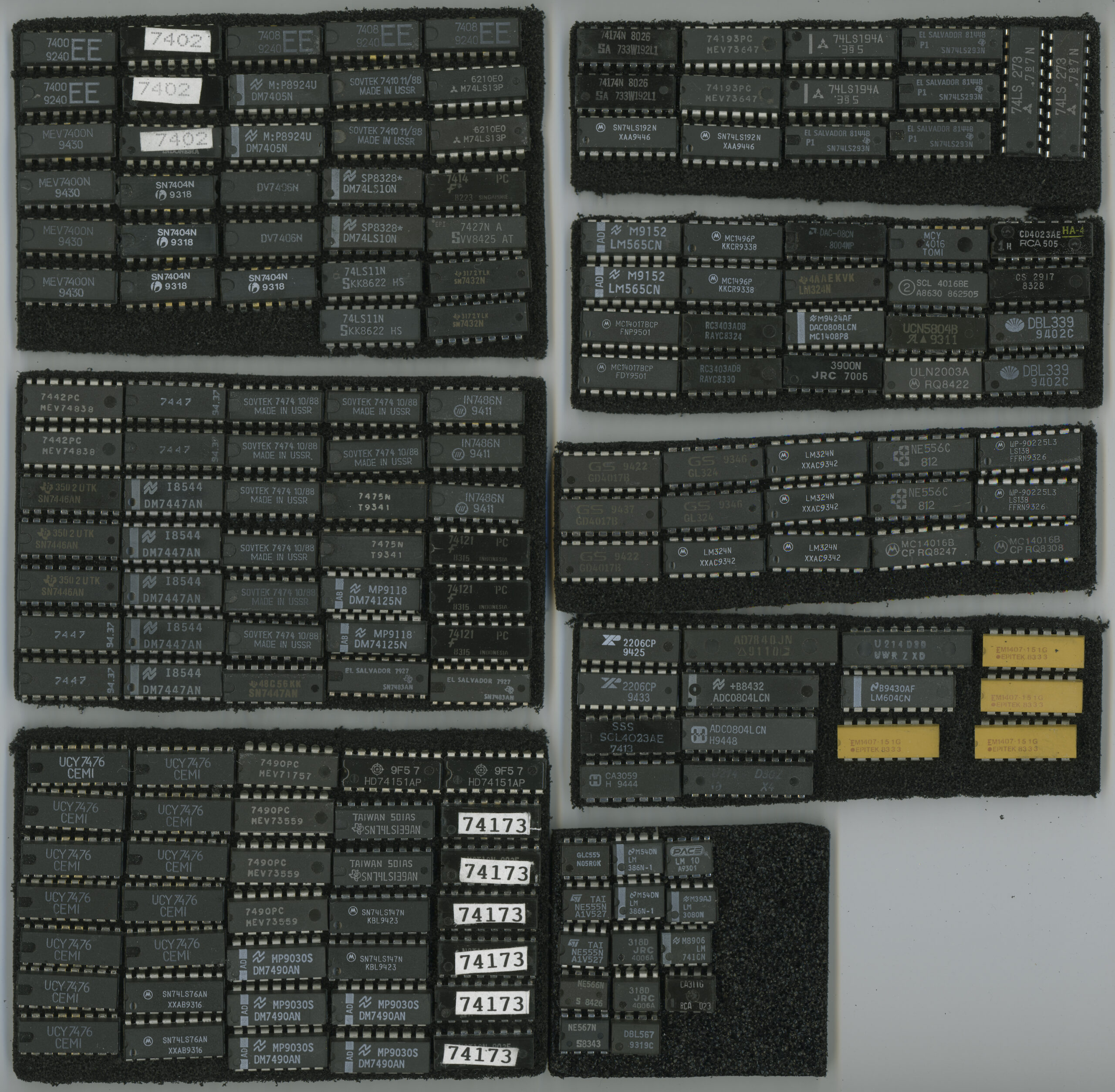
Remember the SOVTEK ICs and random other electronics I received as part of an ITT toolbox from a coworker?

Well, tonight I decided to go through and sort through the ICs, tossing out the noticeably physically damaged ones, and cataloging the rest. That scan up above shows all of the ICs, about half 74xx series, on foam. If you’d like to see a list of what is there, I put it all in Google Documents and shared it here. (And yes, Google Documents works pretty darn well.)

The yellow things are resistor arrays / networks, and those aren’t in the catalog.

Maybe now I can get to putting together that synth-like thing, or something else nifty. (Perhaps a LED clock or something…)

electronicsmaking thingsmoved from livejournal

WTF?

Ever written a bit of software, looked at it the next day, then not been able to figure out what the hell you were doing?

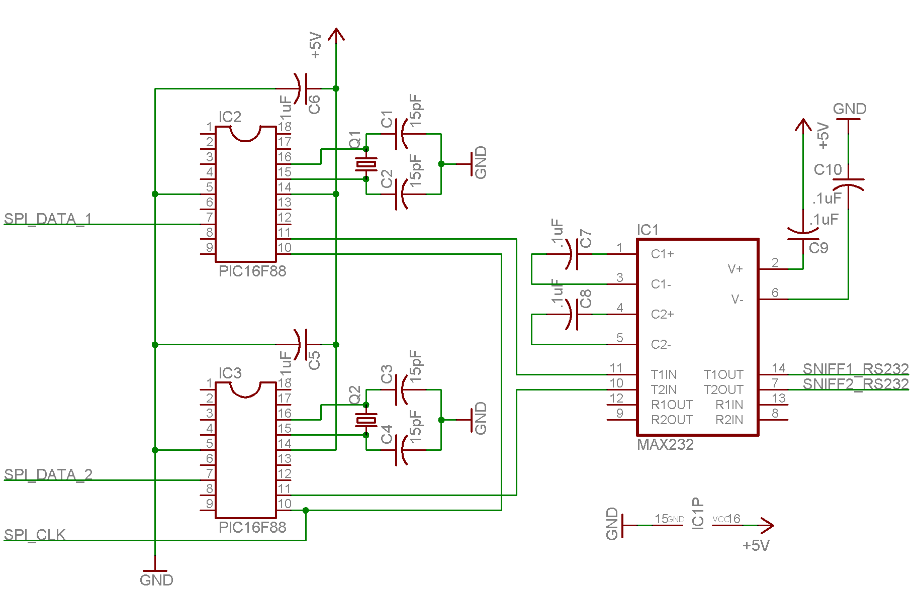
If I didn’t somehow forget to save after the last compile, it looks to me as if the odd captured data from last night is complete garbage, because I was feeding the SPI data straight into the MAX232. That… I don’t know how I could have gotten that wrong.

computerselectronicsmoved from livejournal

Protocol Disappointment

I ran into some headaches with electronics tonight. First, I tried to get recognizable data out of the Honda Music Link, using most of the hardware mentioned last night. Unfortunately, this didn’t work out as I hoped. While the PIC and NEC-branded IEbus controller communicate via SPI, a Control / Data line is also used. This means that the data I sniff in either direction could either be control or data, and without knowing the state of that line it’ll be even harder to figure out the protocol.

I’m thinking that the best thing to do (if I want to continue the project) is to pick up a PIC with two SPI lines, so I can read both of them into buffers at the same time. Then I can also check the status of C/D, bundle all this together, and easily output it to the PC, already in a somewhat readable format.

Or, I can just stop working on the project again.

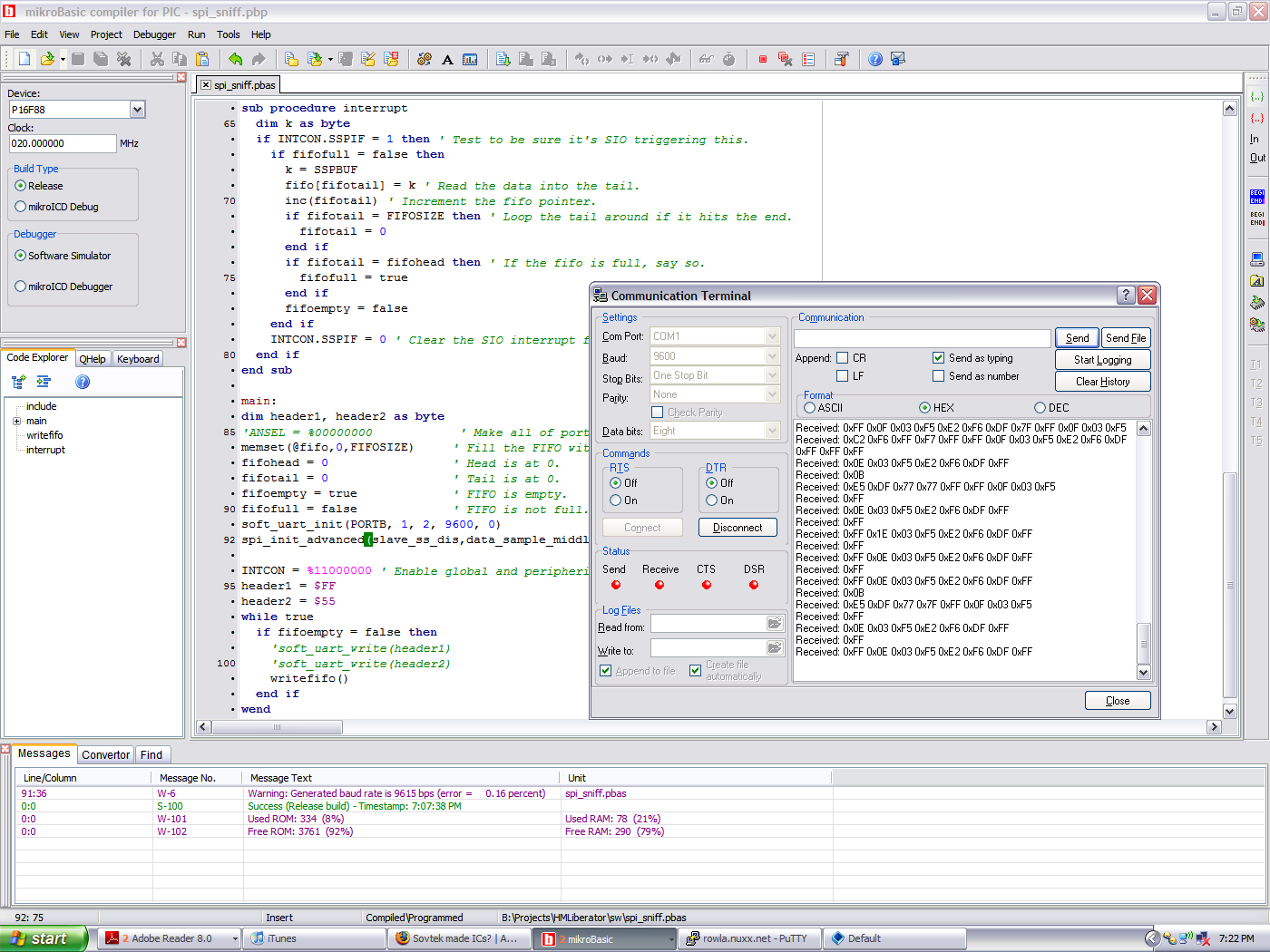
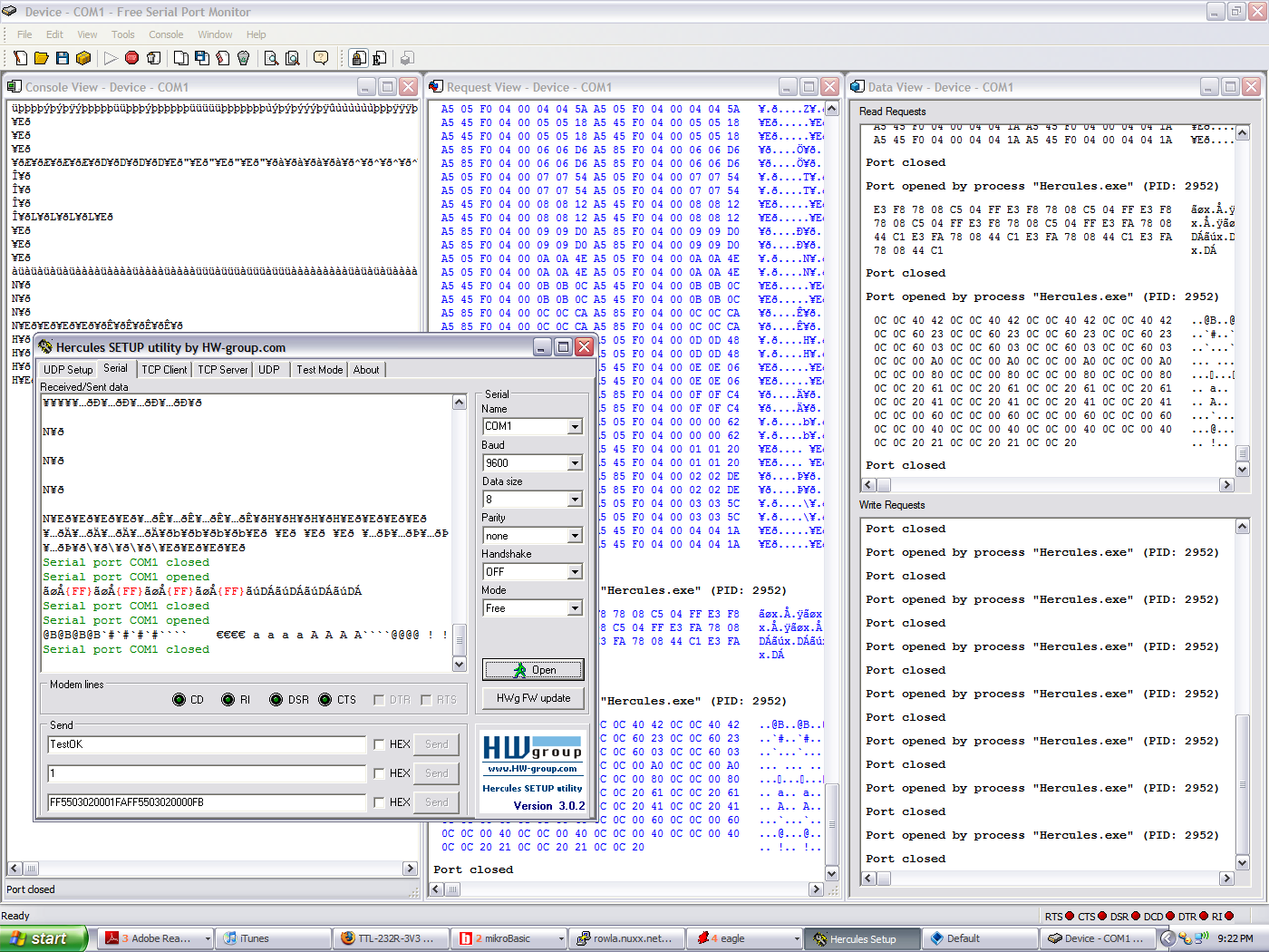
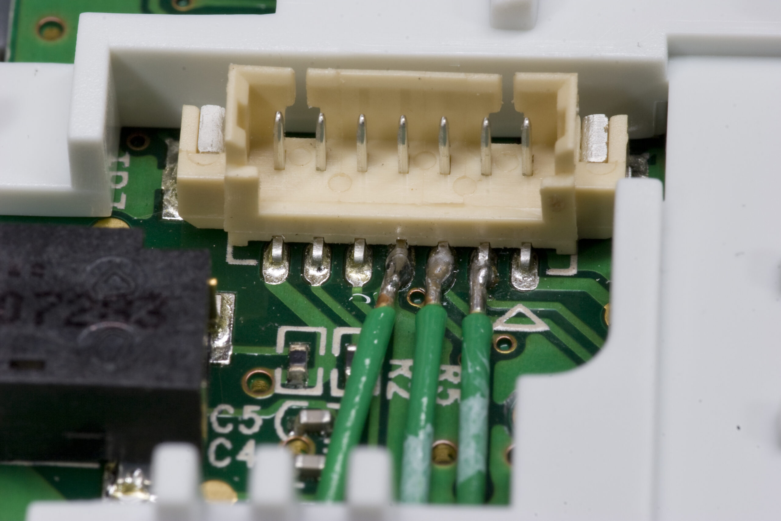
After getting frustrated with that, I decided to tear into the Xbox 360 Chatpad (photo gallery retired) and see if I could figure out what it is spitting out. Well, the short answer is that I couldn’t. I was able to see something, but I’m not sure what it is. (Screenshot of data being captured.)

The serial data is 0-2V when coming out of the 360, and it appears to do some regular polling, back and forth. I couldn’t figure out the baud rate and whatnot, so I couldn’t really tell if what I was seeing was valid data or not. That said, it’s a start.

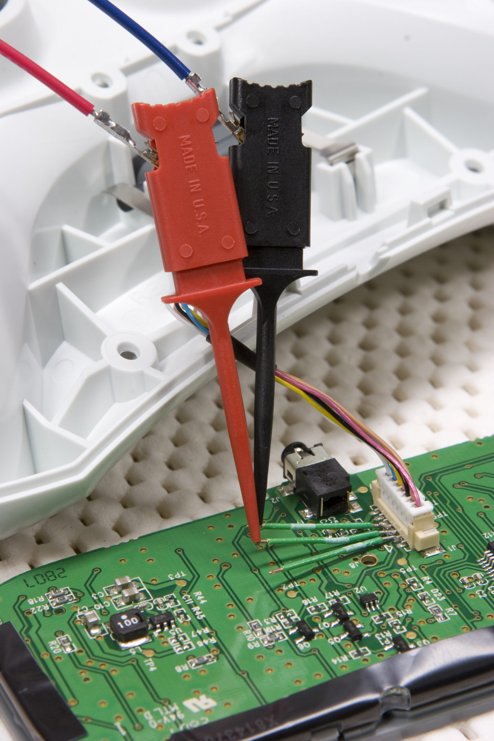
Here’s two more photos:

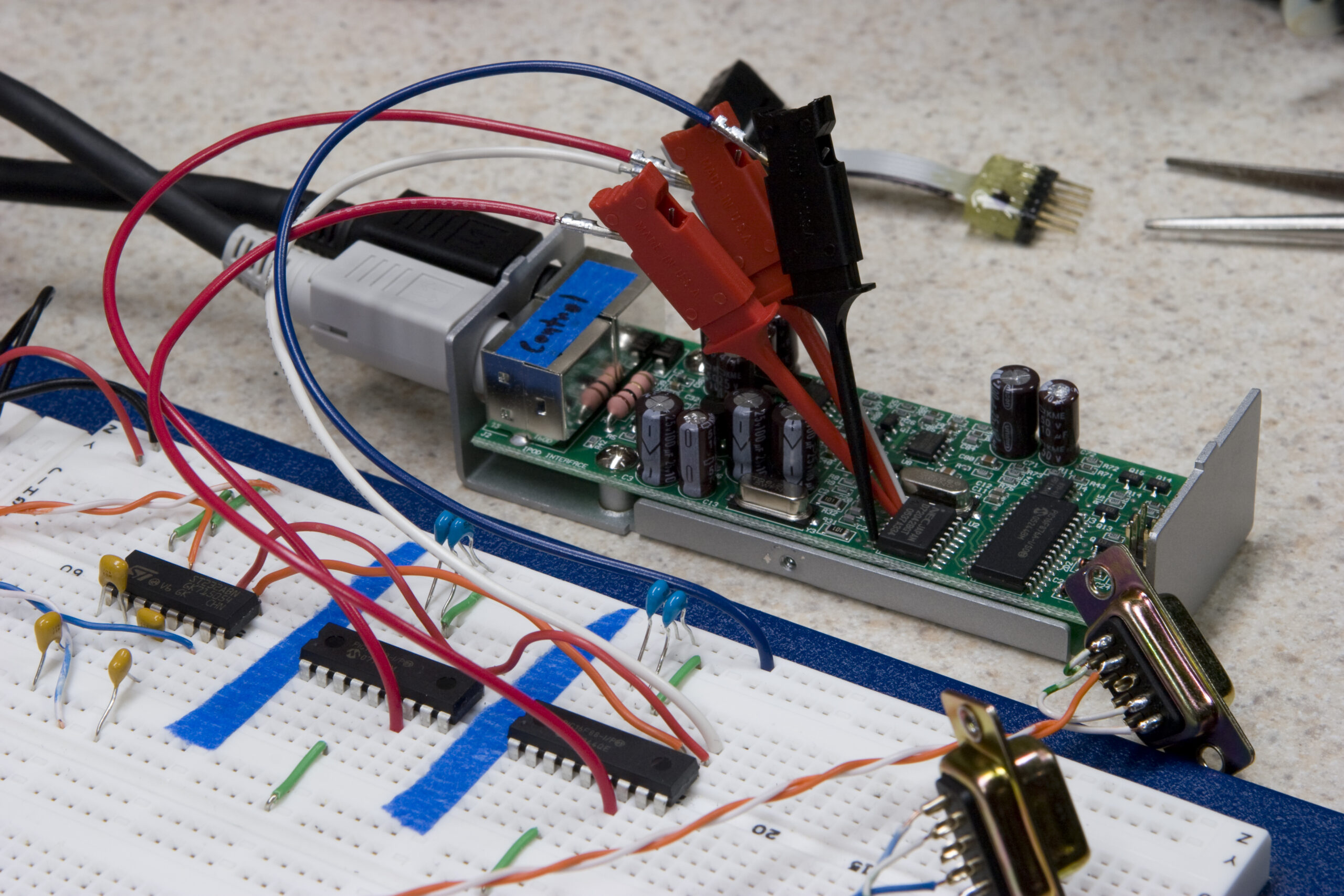
· Test leads connected to Chatpad.
· Detail of leads soldered to internal Xbox 360 Chatpad connector.

automotiveelectronicsmoved from livejournal

HML Sniffer

I finally got around to putting together the SPI sniffer I mentioned back on 26-July. The only problem is that I left all the crystals in my cube at work, so I couldn’t give it a test run tonight. I think the software is functional, but I have no good way of being sure yet.

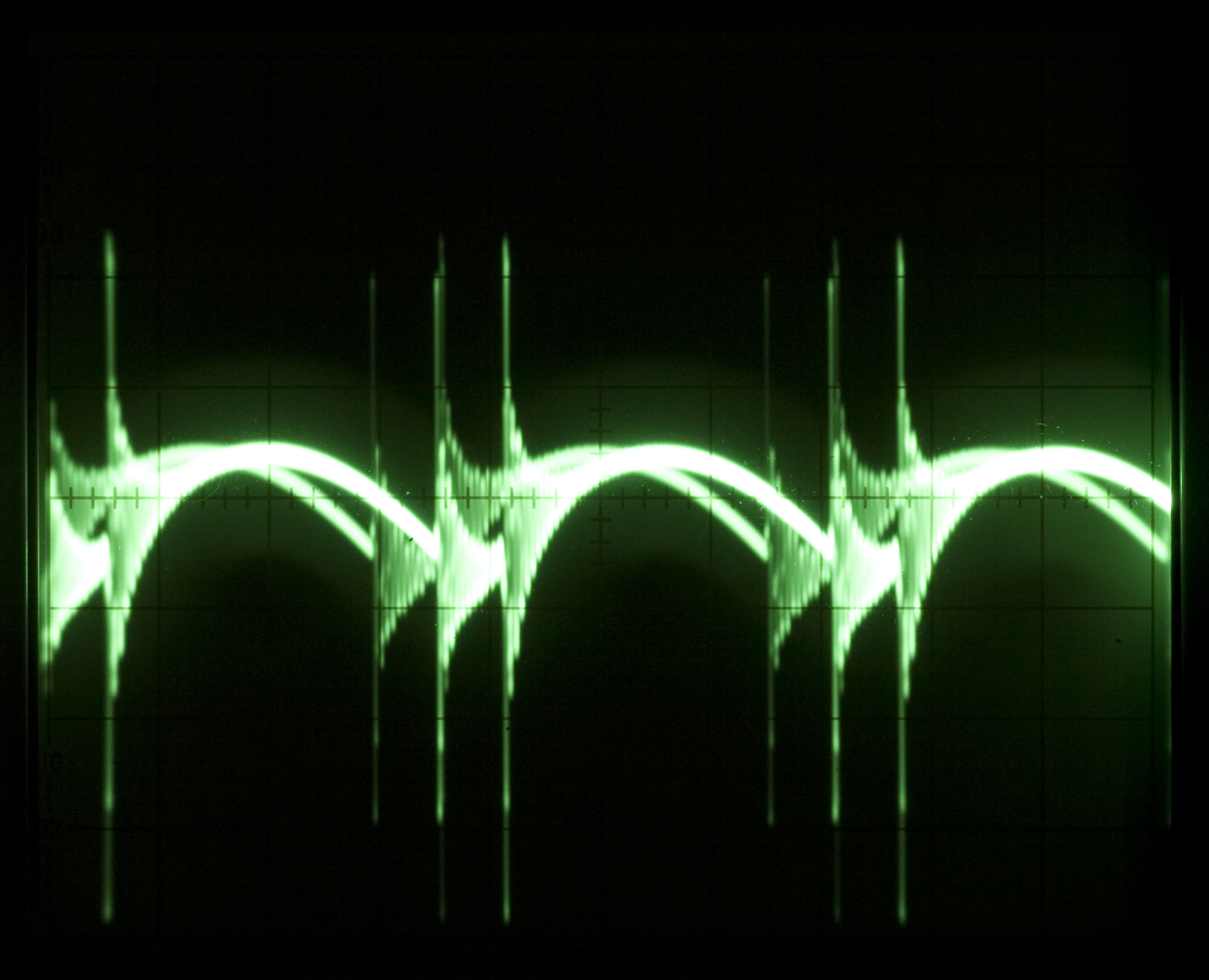
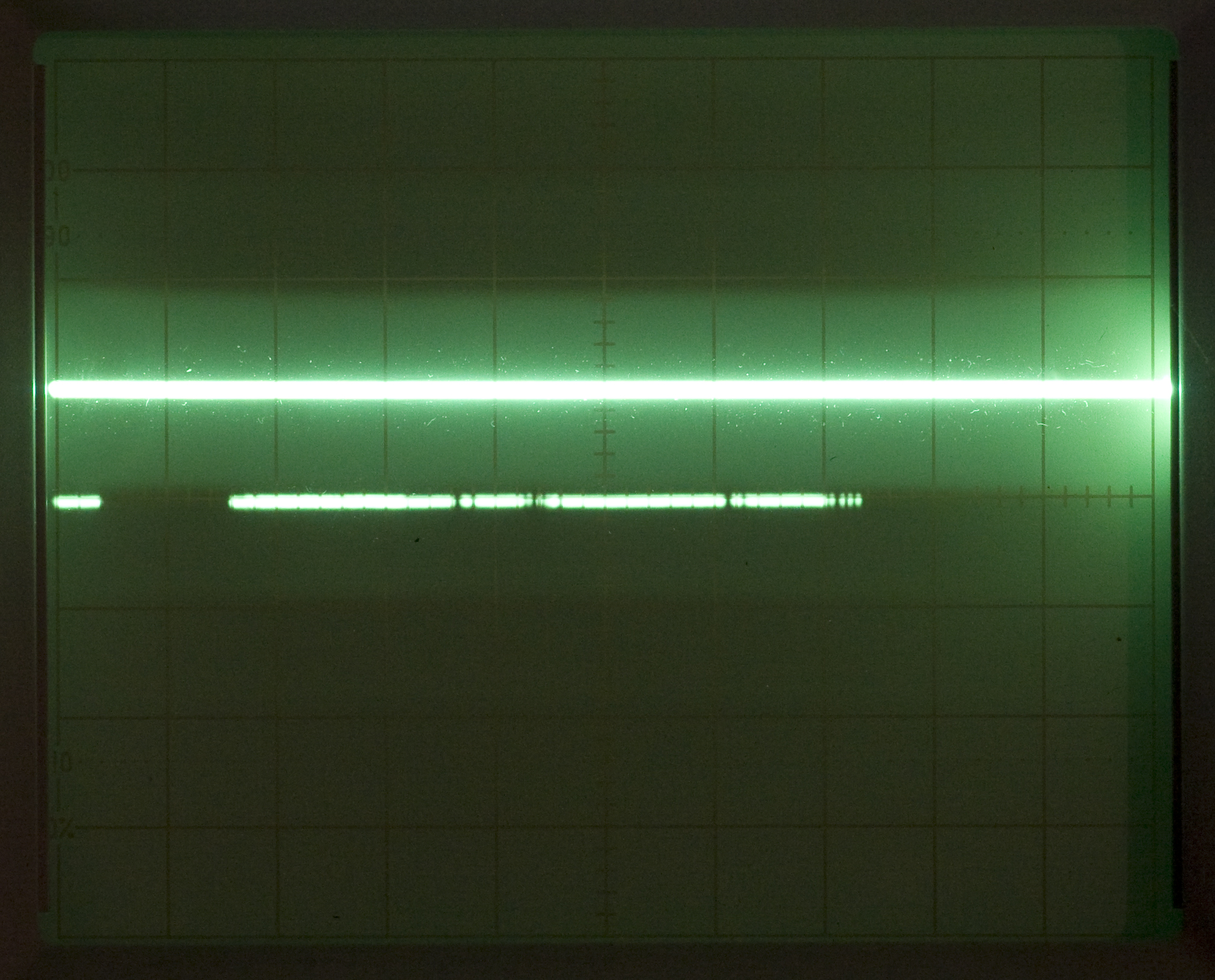
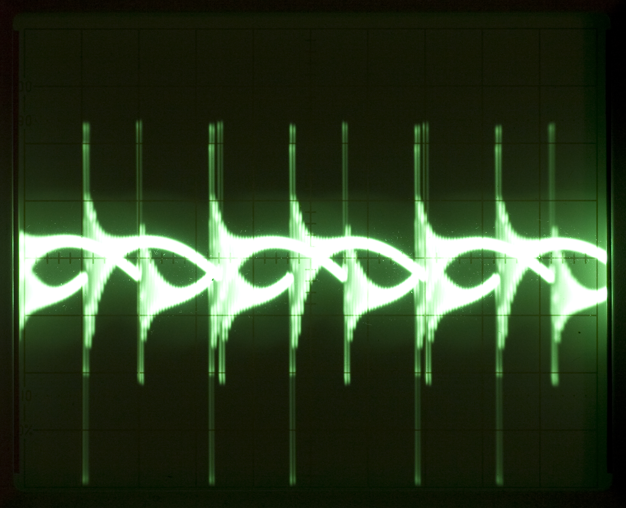
Oh, there is also this photo of the oscilloscope screen showing little blips of data, from when I hooked the scope up to one of the SPI lines, just to be sure that I could see something.

Most of tonight was spent putting together things on the breadboard, making the DB9 cables, making the leads for the micro clips, and writing the interrupt handler (feeds SPI data into the FIFO for writing out via the UART). Hopefully I’ll get more done tomorrow. My hope is that by the end of the Thanksgiving weekend I’m able to understand what is going on between the PIC and IEbus controller, and thusly (hopefully) the rest of the vehicle. From there I will (hopefully) be able to start getting an idea of what actually needs to go into firmware for the HML itself.

automotiveelectronicsmoved from livejournal

Sovtek ICs

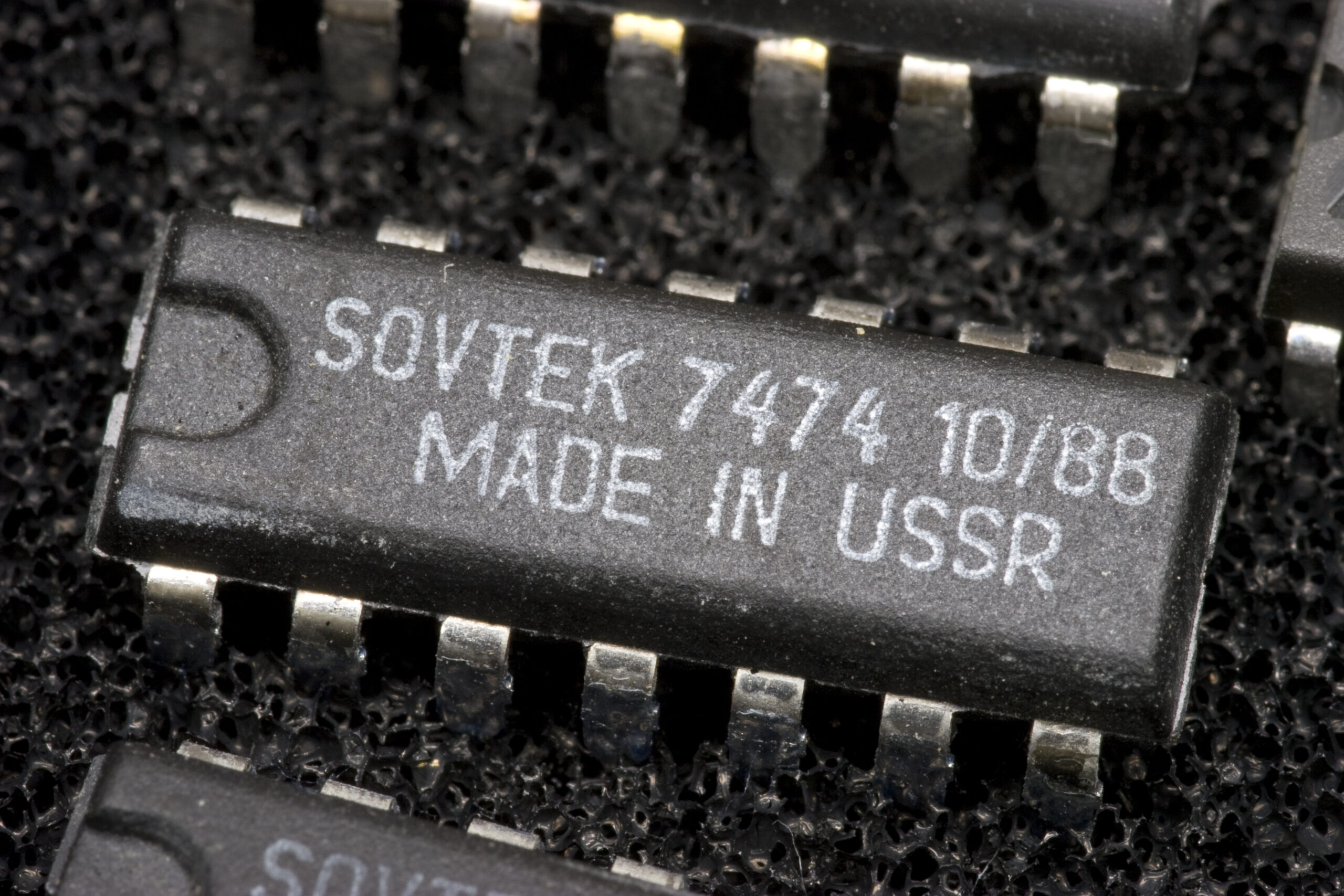
Sovtek 7474 IC

I wasn’t aware that Sovtek ever made ICs. Then again, it might not be the Sovtek which is so well known for its guitar parts and tubes and whatnot. Beyond that 7474 there (and it’s eight or so peers) I’ve also got a couple of 7410 parts.

So, where did I get them?

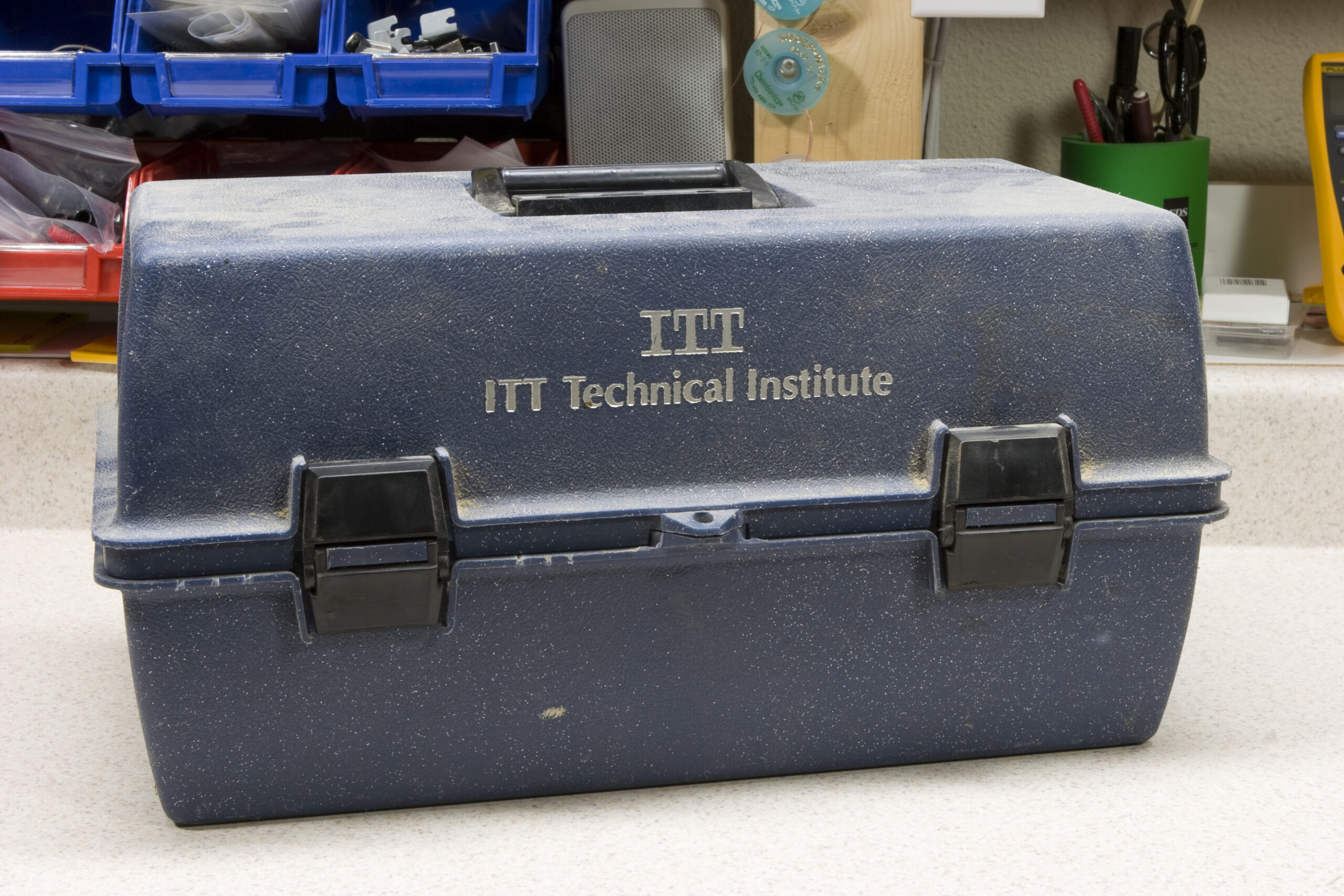
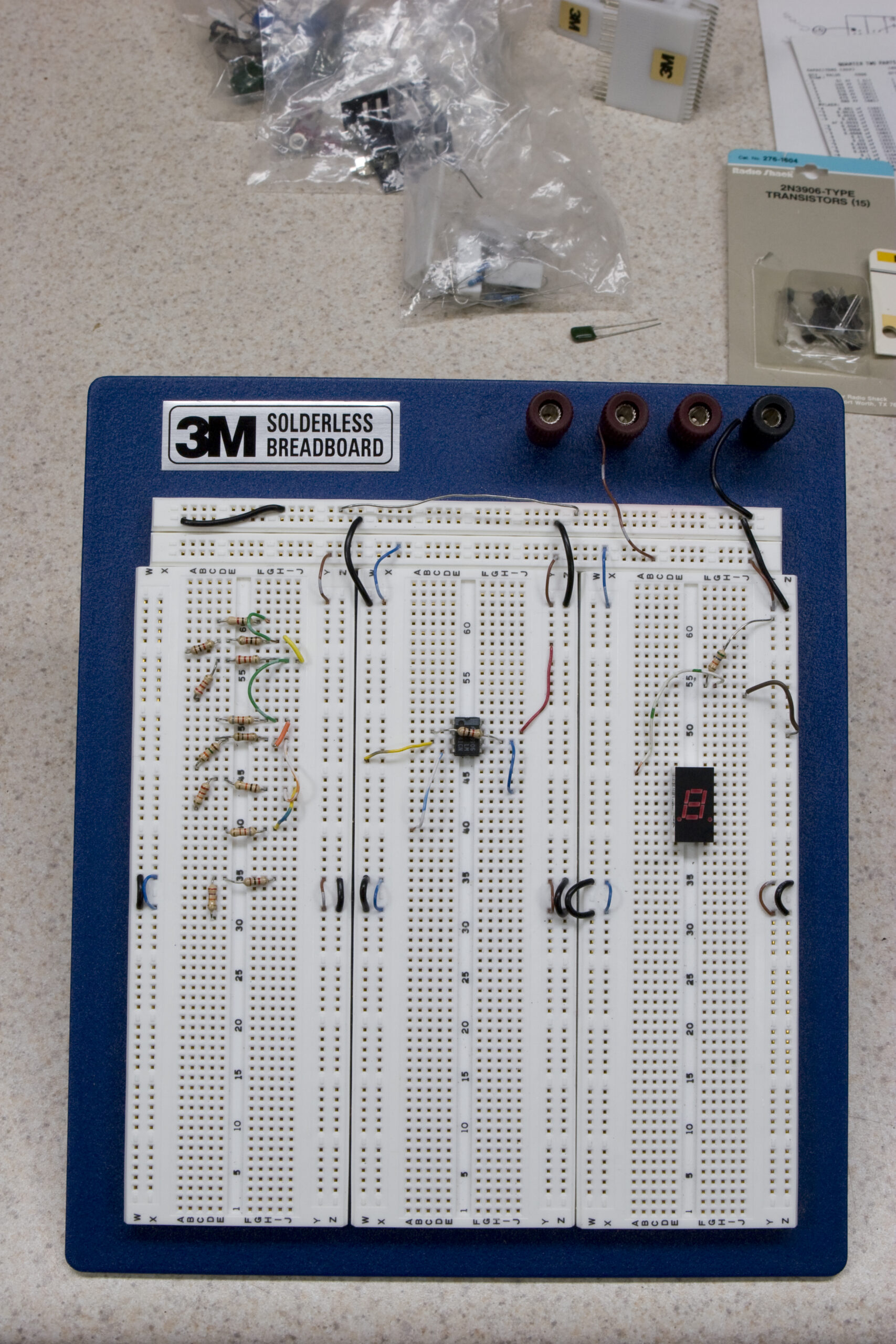
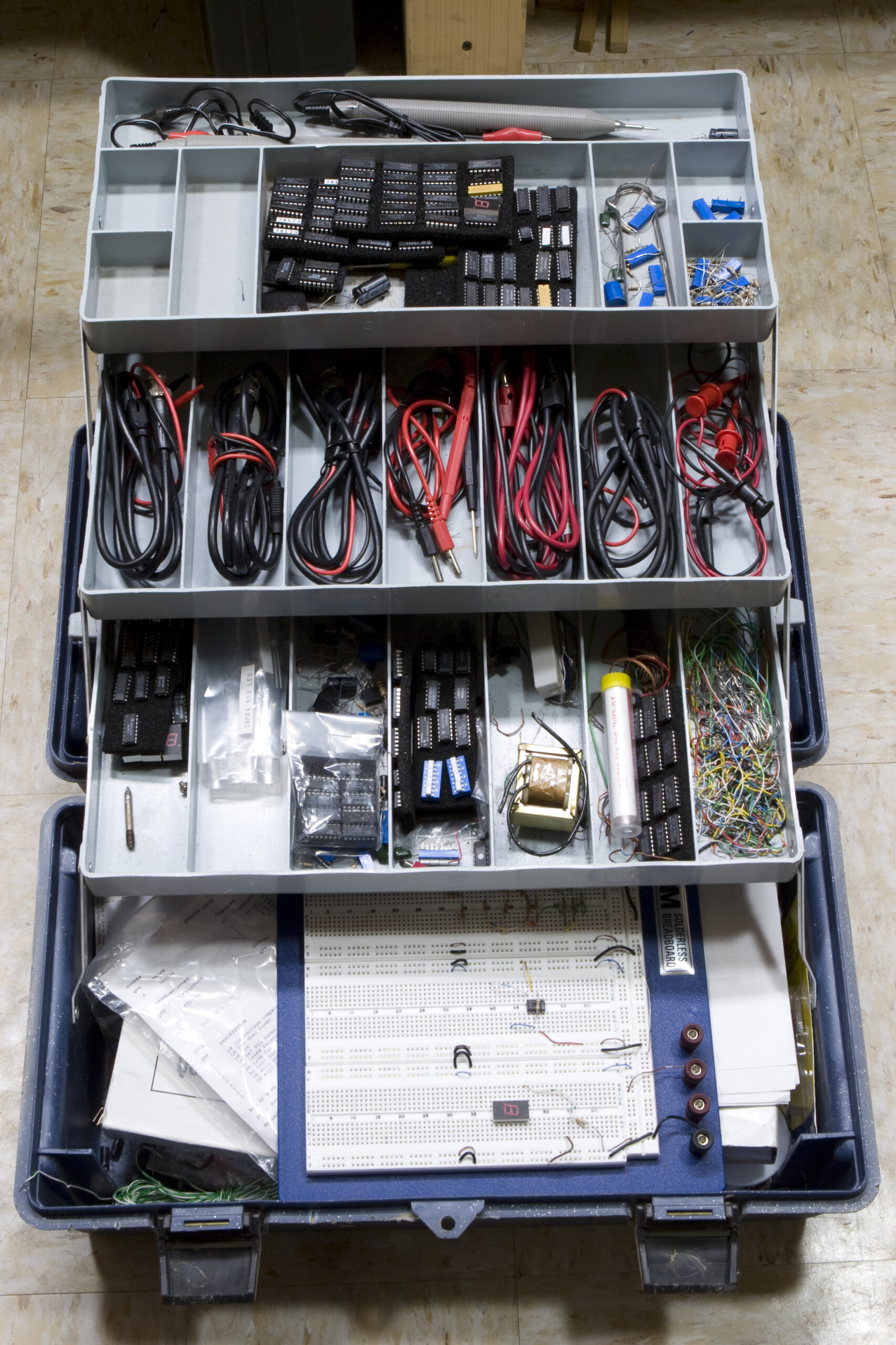
Well, my coworker Jeff had, sometime in the mid 90s, attended one of the local ITT Tech schools. As part of this he received a rather large toolcase which he used to store the electronics parts and tools he used. A few weeks back he told me that I could have his old breadboard, which would be quite handy as I’ve started to find my current one a bit cramped at times. Well, instead of giving me just the breadboard, he gave me the entire case full of stuff, including cables, trays of ICs, and a whole bunch of loose parts.

Tonight I spent some time cleaning out the case, throwing out all the loose resistors, electrolytic caps (I’m not stupid enough to keep mid-90s caps), bits of wire which aren’t of the heavy / pre-tinned version designed for breadboard jumpers, plastic bags, and the other hard to identify / low cost / broken parts. What was left over should be quite handy, especially because I’ve had a strong desire to do some things with discreet logic.

These parts include:

· The aforementioned ICs.
· A large handful of ceramic caps.
· Twenty or so mixed inductors.
· Loads of Pomona cables, typically for connecting to multimeters with BNC connections.
· The really nice, large breadboard.
· Lots and lots of ICs, mostly 74 series, ADCs, and opamps, many of brands I’ve never heard of.
· Mixed older optoelectronics.
· Logic probe and pulser.
· Other stuff, which I’m sure I’m forgetting, but looked useful so it wasn’t tossed…

So, this should be pretty neat. I might finally have enough parts laying around to play with doing some things with discreet logic. Now… What? It would be interesting to maybe design a small tabletop analog synth. Maybe something like the PAiA FatMan but easier to build, in a better case, possibly lower cost, and wholly open source. Hmm… After the audio switch, of course, and the (likely) for-pay project that I’m hoping to wrap up soon as well.
acquired thingselectronicsmoved from livejournal

Fudge Ripple

That’s the AC ripple from the power supply mentioned here, when connected to a 10 ohm 10% 10W power resistor, sinking ~490mA. The scope is set at 10mV and 5uS per division, probe at 1x, AC mode. In that image it’s being fed about 36VDC. Cutting that in half using only half the power supply (about 18VDC or so) gives this waveform, with marginally less noise.

The way I see that, peak to peak noise is about 50mV, so just about 1%. I think RMS would actually be a good bit lower, but my scope won’t figure that out for me and I think it’d be a lot of work to do it by hand. So, I think this should be an okay design… This is also on a breadboard, and something well laid out actually with a groundplane and all should be even better.

I might head downstairs and pull out the second filter (inductor + capacitor) and see how much more noise it adds, but I’m fairly certain that it’ll be quite substantial.

One thing is for certain, I really could use a better scope. I’m very tempted to just buy a refurb, $547 Tek 1002. However, I think I’d really rather have one of the B models, which adds serial and USB ports for getting data (screenshots, etc) right out of the scope.

electronicsmoved from livejournal

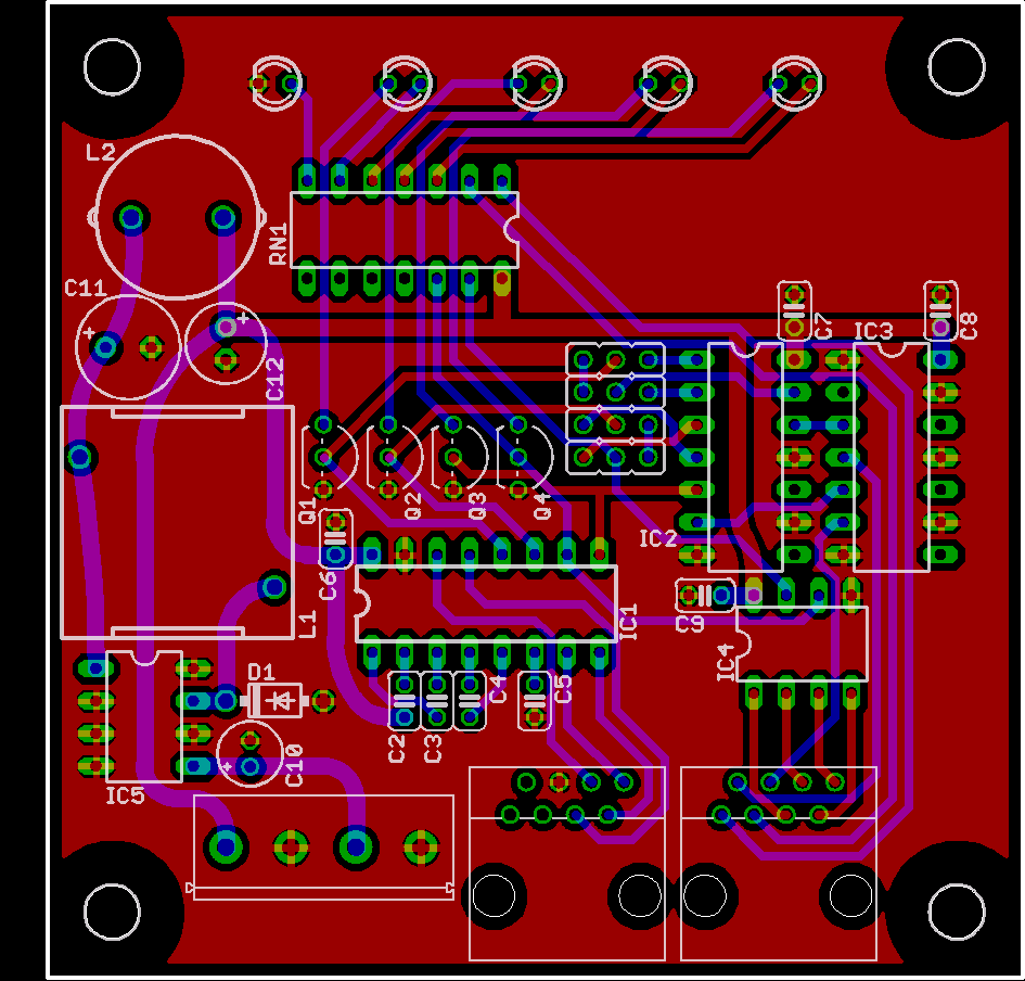
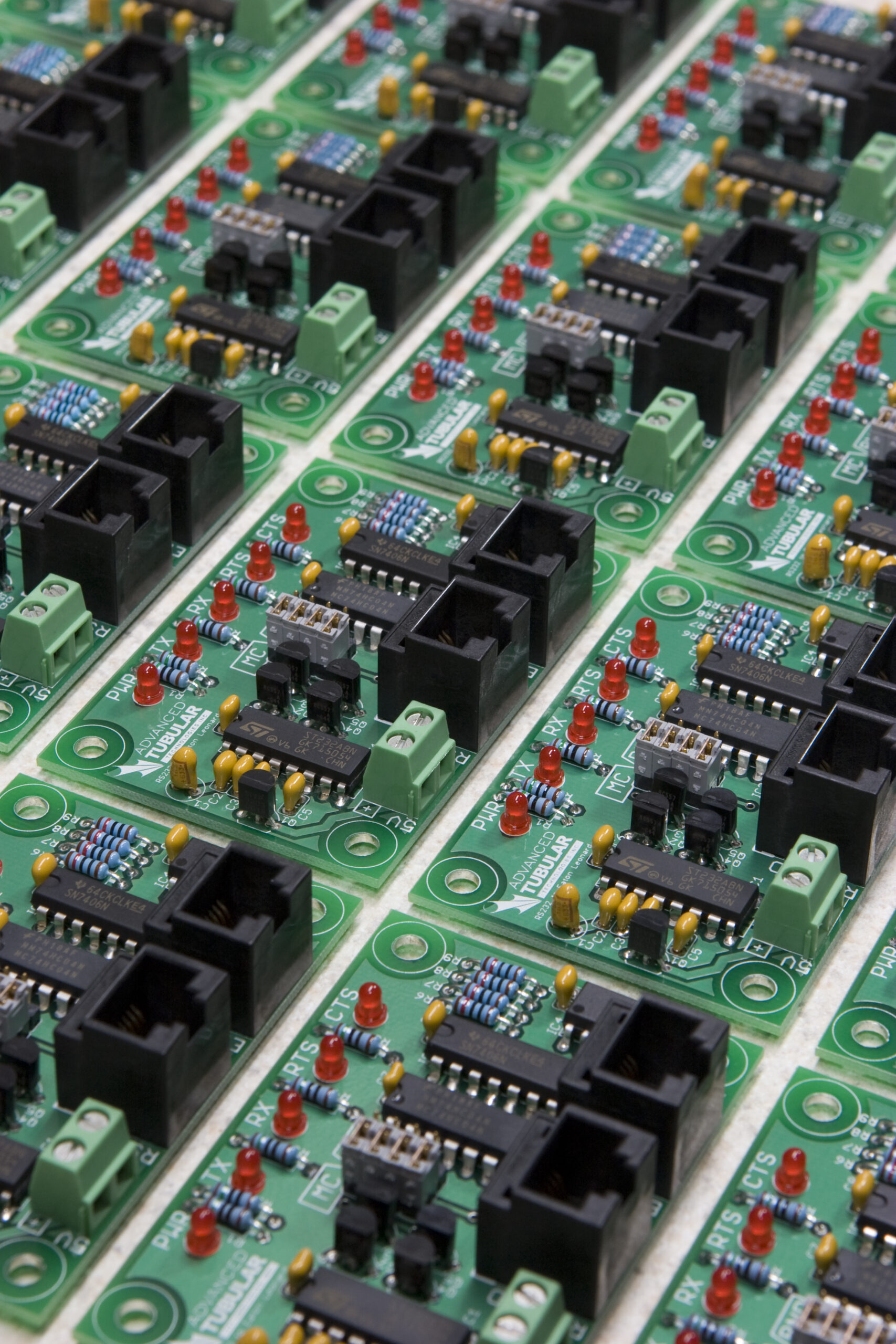
RS232 to Eaton Leonard Interface, 24V Version, First Draft

Remember those RS232 to Eaton Leonard adapters I made a few months back? Well, there’s a need for me to develop a version which can run from 24VDC, so I did. The switching power supply mentioned a few days back is used in this (you can see its footprint there on the left), with the rest being the same as the other board.

I had to remove the reverse voltage protection (it just won’t really work with the high potential input voltage this needs), I’m using a resistor network instead of discreet resistors to make assembly easier, selected different LEDs (ones that use slightly higher current to go with the 120R network), and laid out the whole board again.

That picture up above is missing the documentation and logo layers, just to obfuscate things a bit. I may also tweak a little bit of the design, but I think I’m happy with it. It’s now 3″ x 3″ instead of the original 3″ x 2″, but that extra three square inches is needed for the power supply. Yes, there’s a bit of blank space still, but I don’t think it’s enough to make shrinking the board worthwhile. The cost difference between the previous PCBs and these is pretty much nonexistant, if I’m remembering the quote right.

I think I’m going to keep compacting the board. Hmm…

UPDATE: I just shaved a square inch off the board by bringing the top in 1/4″. LEDs were compacted a bit, logo made smaller, L2 moved, and more.

electronicsmaking thingsmoved from livejournal

Electronics Stuff

Gah. I just blew (or just noticed that I blew) the 440mA fuse in my DMM. Mouser carries the part but it costs US$22! Grainger carries it for US$8.65

I was able to stop at Radio Shack on the way home and get some 10W power resistors for testing the power supply. I’m having no problems getting about 490mA out of it, which is more than enough for its intended application. Unfortunately the resistors get fairly hot when sinking that much current, so I can’t run them for too long.

Still, things are good with that… I guess I’ll finish part footprint validation and get on with laying out the board.

electronicsmoved from livejournal

Switching Power Supply

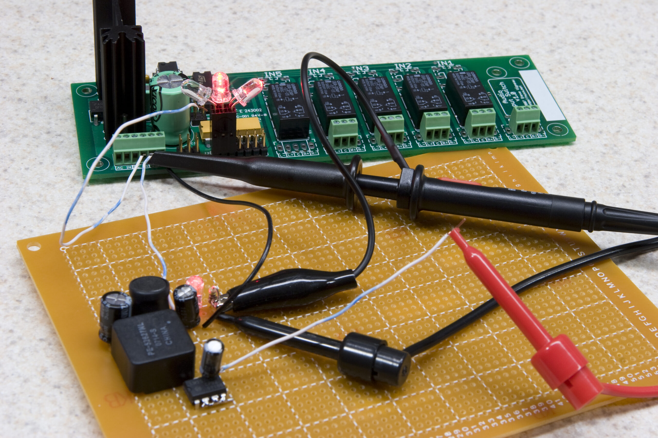
Well, the prototype power 5V switching power supply that I cobbled together seems to be working. Up there you can see it powering the first nuxx Audio Input Switch, just to give it some sort of load to work on.

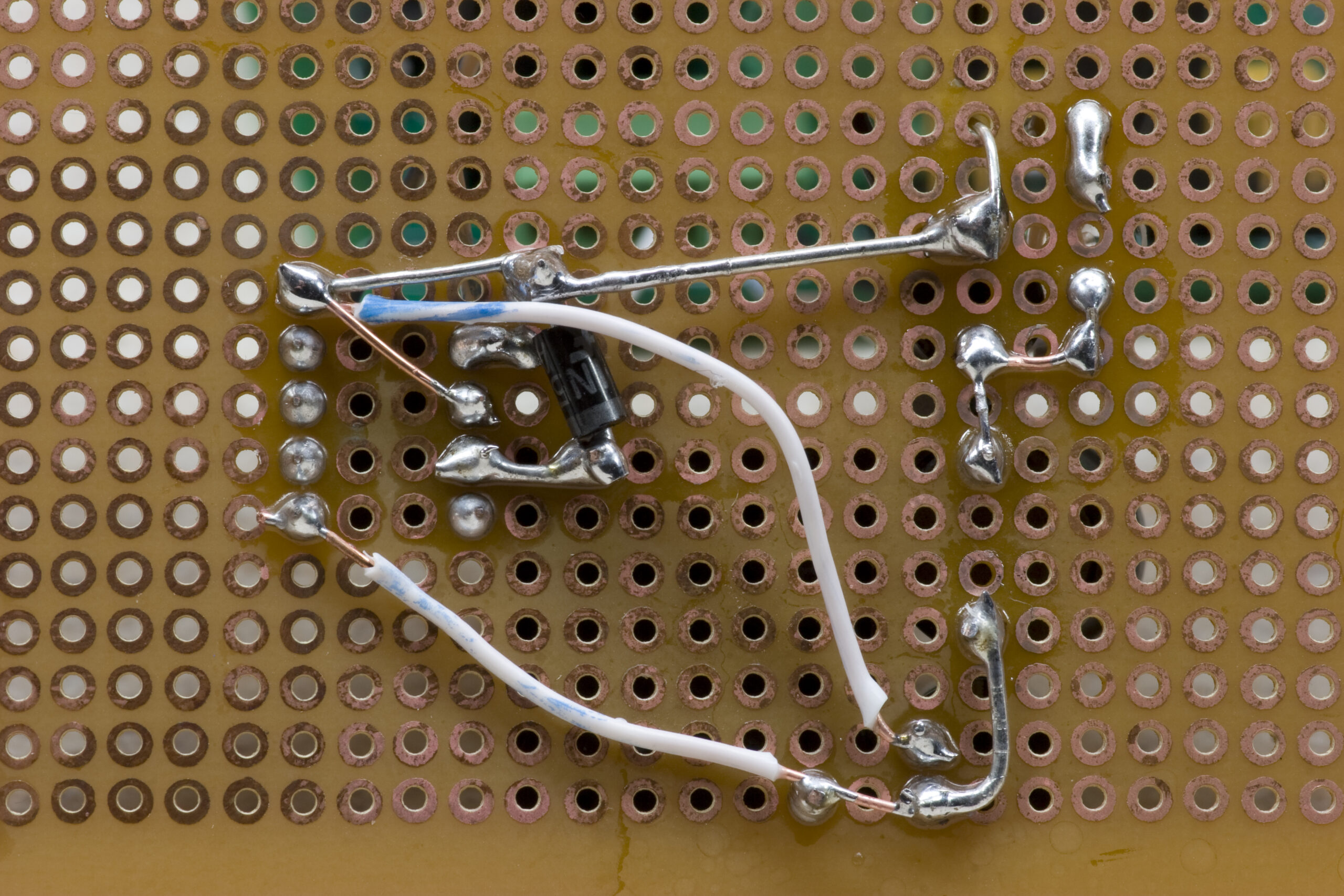
Here is a photo of the bottom of it. It’s clearly hacked together, just sort of built up on the board so I could have solder connections and reasonably short wires. When I tried to breadboard it things didn’t work quite right, which I blame on switching power supplies being touchy about long rows of bare wire.

It’s pretty much a reference implementation (some variances in parts) and it produces what appears to be nice, clean power. I can’t see any noise on my scope. Granted, my scope is pretty crappy, but it does seem to show some noise when it exists. (I can’t afford a new scope yet…)

I’m happy with how it is working thus far. I need to put a bit more load on it, but that’ll be done over one of the next random couple of days. For now I can say that it had no problem giving me an even 5.000 VDC while powering the nAIS above and being fed 6.073 VDC. If I cranked the input up to 35.93 VDC (the highest I can get my benchtop power supply) the power supply was pushing out 5.074 VDC. Pretty good, I think.

electronicsmaking thingsmoved from livejournal

TV-B-Gone

Danielle’s TV-B-Gone
(Click for full res photo…)

Tonight I helped Danielle put together her first electronics kit, one of Limor Fried’s open-source TV-B-Gone kits. She’s soldered a bunch of stuff before from when she briefly went to Kettering, but this is the first functional kit. And, of course, it works!

Well, it at least turns off my TV almost instantly… I imagine that it’ll work pretty well on whatever other ones. At $20 it’s a good, and useful first kit… Imagine actually being able to turn off all those annoying TVs in places like the doctor’s office waiting room, school hallways, and (hopefully) the advertising things on gas pumps.

electronicsmaking thingsmoved from livejournal