Help with Millet Hybrid Maxed Troubleshooting
(I just posted the following here on the Head-Fi Forums. Hopefully someone there can help me.)
Hey there... This weekend I finished up my Millett Hybrid Max (with MOSFETs) and while it was working great at first (Saturday), I'm now having some problems. I'm hoping that someone here can give me some pointers on where to look.
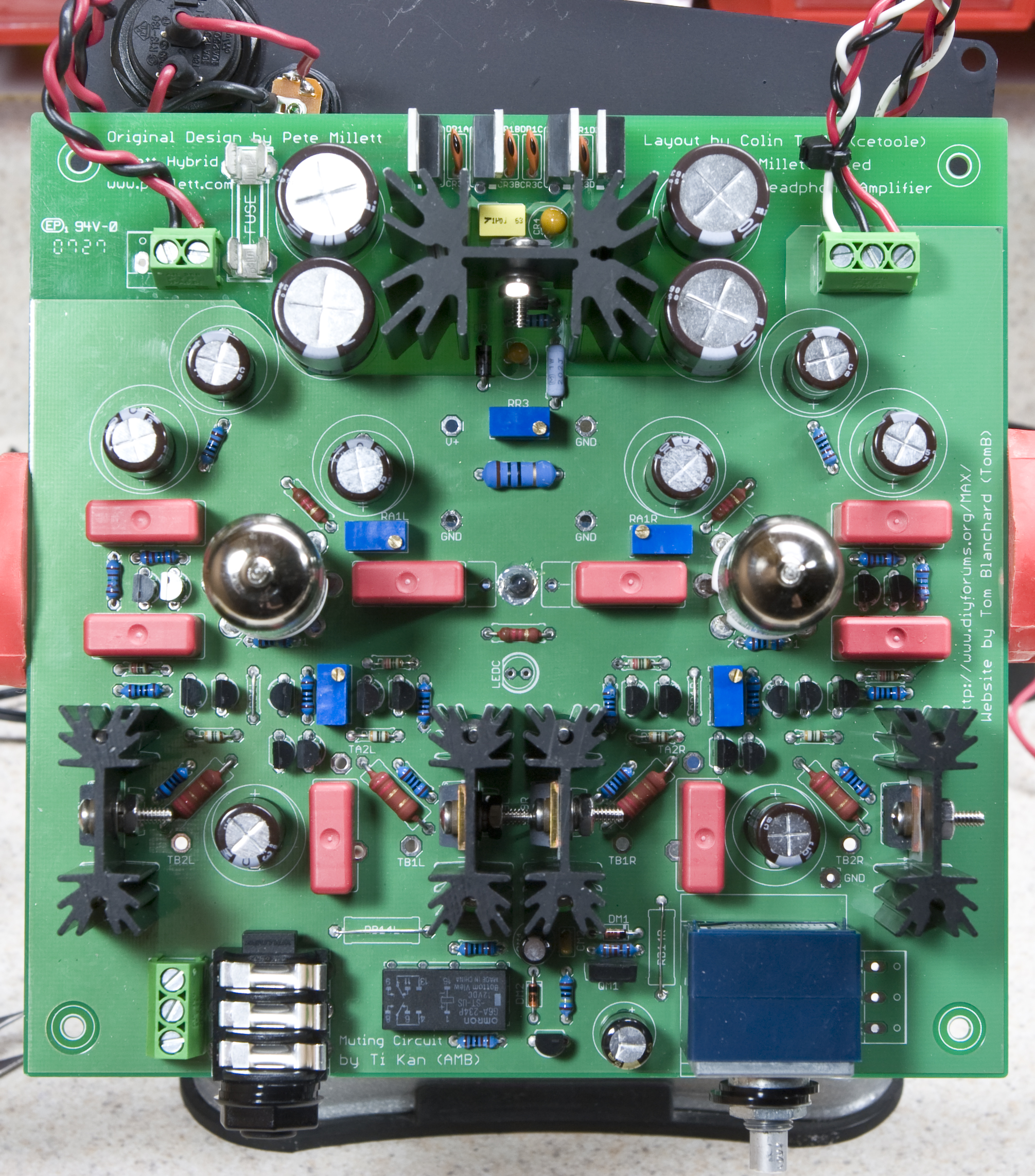
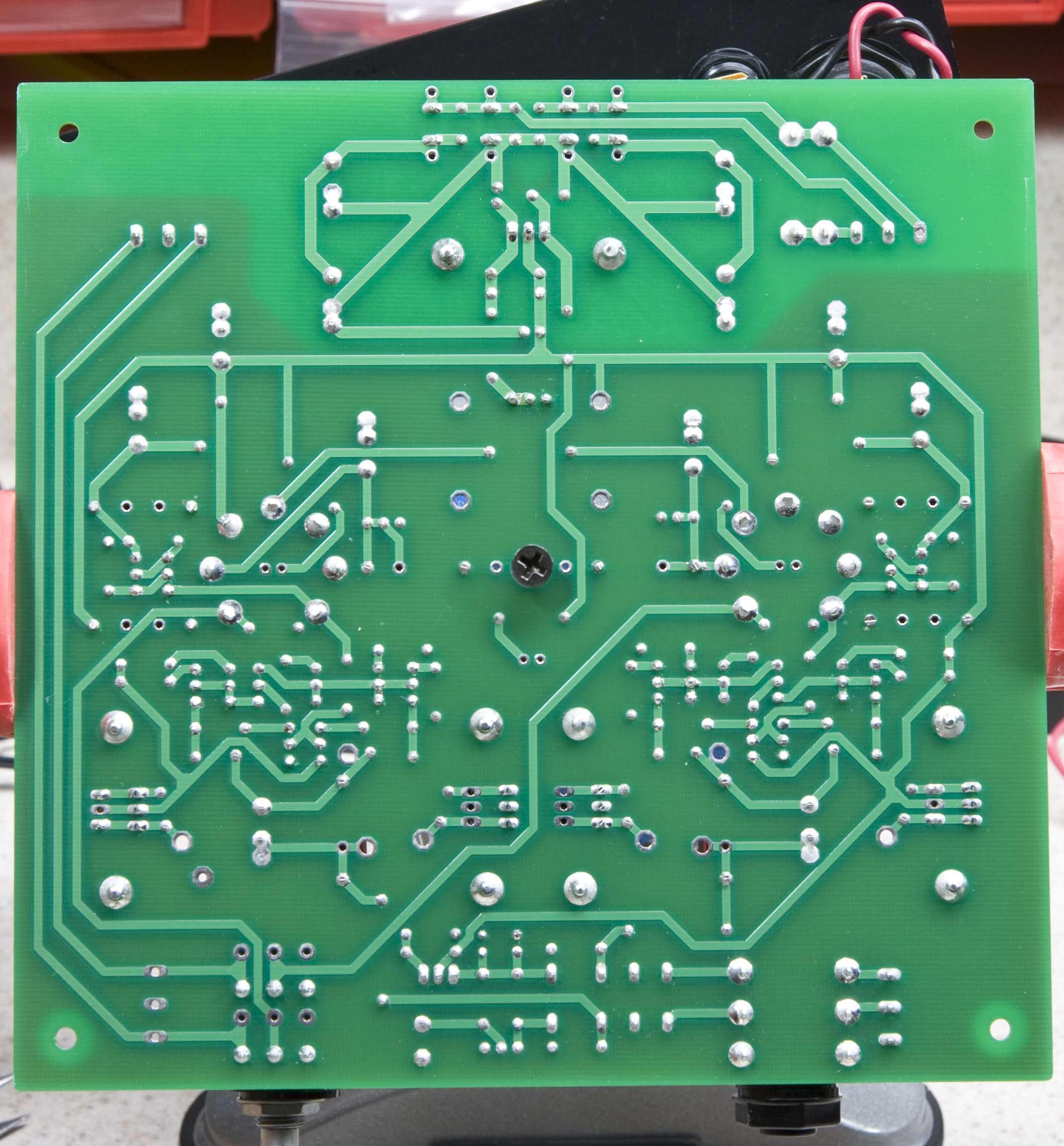
First off, here are photos of the top and bottom of the PCB: Bottom Low Res, Bottom High Res, Top Low Res, Top High Res.
My soldering is generally pretty good, but please note that all the connections look dull because I'm now using lead-free solder for board work. As can be seen on this page (photo gallery retired) my enclosure is almost exactly the same as cetoole's, including the vent holes for the heatsinks. When it was working the chassis never rose above slightly warm (around 100°F) in a 75°F room, so it seems to be vented well enough.
The power supply is a Jameco-brand 24VAC 1A wall wart. I've used their supplies before and they've been quite good in the past. For fuses I've been using either 800mA or 1A fast-blow fuses. When the amp was working the 800mA was sufficient at levels as high as the maximum I could stand (about 10 o'clock).
Power, audio inputs, and headphone jack are all isolated from the chassis, and their isolation has been confirmed with a continuity meter.
Here's a rough timeline of how the build / testing went and problems I had along the way, which will hopefully help point the way:
- Finished assembling everything, and on powering it on I found only ~2.6VDC from the power supply, regardless of the position of RR3.
- Found that I was bit by the backwards silkscreen on the trimmers, so when I thought I had everything turned down all the way for initial setup it was actually all the way up.
- Properly turned all the trimmers down, powered things on, set the power supply to 27.00 VDC.
- Biased the tubes to 13.50 VDC.
- Biased the MOSFETs to 200mV, which is right in the middle of the range suggested on the MAX Setup and Bias Settings page.
- Hooked up a CD player (random Yamaha changer) and headphones (Sennheiser HD570) and confirmed that I could hear audio.
- Left the CD player playing Radiohead's Kid A on repeat for 4-5 hours with the volume at listening levels.
- Checked the power supply voltage, tube bias, and MOSFET bias and returned them to the settings previously mentioned, as they had drifted slightly.
- Checked the heatsinks with a thermocouple and found them to be around 125°F.
- Listened to a few different CDs and some DVD audio and was happy with the sound.
- The next day I went to hook up my iPod, but I wasn't getting any audio from the left channel. Turned everything off, removed the tubes, looked around, reinserted the tubes, and noted that everything seemed to work.
- Listened to a few more CDs, then found the left channel to be a bit lower than the right. I figured that the MOSFETs needed to be biased again, so I decided to set it aside and open the case the next morning.
- Listening more the left channel started dropping out completely, and during a test while listening to Squarepusher's Tetra-Sync (a 10 minute track) I could hear the left channel fade in and out, and occasionally get a bit static-y / fuzzy.
- The next morning I began thinking the problem might be with the 1/4" to 3.5mm headphone adapter I was using, so I plugged in a different one and turned on the amp. It wasn't working, nor was it warming up.
- Opening up the amp I found that the fuse (800mA) was blown. From this point on it blew every fuse I've inserted.
In testing, I tried the following with no success, with fuses continuing to blow each time:
- Replaced the left tube with a spare NOS 12AE6A.
- Removed the board from the enclosure.
- Replaced both tubes with spare NOS 12FM6 pieces.
- With the tubes in place, VCC to GND is at about 33.8Ω, which just about matches the two tube heaters (~12Ω each) plus R1 (~10Ω). No dead short there.
Any ideas? I'm pretty lost at this point...
Thanks very much...
-Steve