The idea of spoilers, and trying to avoid them, for everything from fiction to time-delayed sports matches, is nothing new. Discord and Reddit have special features allowing text and images to be hidden with a spoiler tag so users must click to show the content. I’m planning a post about the things I learned while healing my scraped leg (resulting from pushing a worn out bike tire too hard), and I realized that it’d be good to both show pictures of the wound and healing progress and that a spoiler-like tag would be useful for obscuring some of the images.
After looking around for a WordPress Plugin I couldn’t find any good options for this. There’s some old and abandoned plugins, there are others which obscure text, some parts of larger plugins, but no stand-alone “spoiler” plugin. Knowing what I wanted I fired up my currently-preferred AI coding assistant (Claude) and got it working on what I wanted.
After a day or so of back-and-forth, this is what I came up with: c0nsumer/nuxx-spoiler
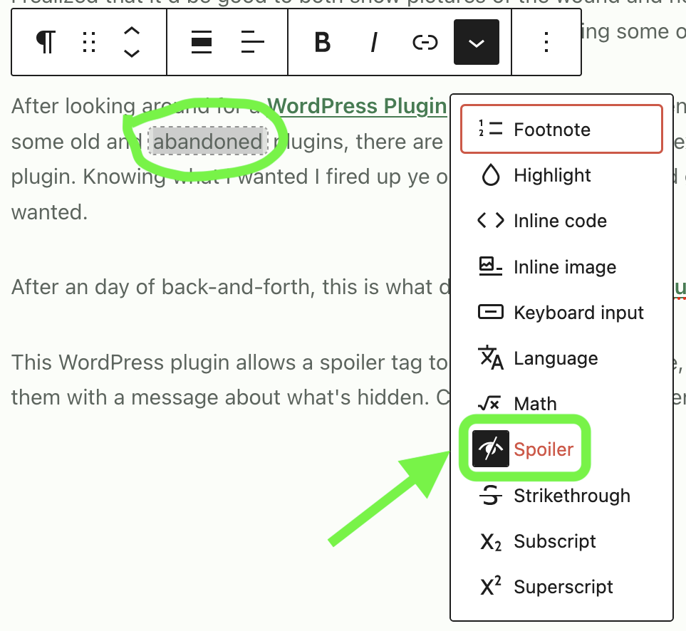
This WordPress plugin allows a spoiler tag to be added to any image, text, or group of blocks, hiding the content with a configurable warning about what it contains. Clicking the warning or overlay then shows what’s behind it; very very similar to Discord’s Spoiler Tags. Below the fold I’ve a number of examples (this also serves as a test post) showing hidden text, hidden individual images, hidden blocks (such as a gallery of images) with the spoiler type (configurable or canned) listed over images. And it’s all nicely integrated with the WordPress editor (as compared to some older schemes that required using code for tagging.)
I’m considering if I’ll submit this to the standard WordPress Plugin repository, but for now I think that keeping it over in GitHub and used here will be easier/best. This way others can grab and use it if they want, but I don’t need to deal with the overhead of supporting a plugin that I don’t have a deep care for about and put minimal (AI) effort into. (If I do this I’ll need a better name, slug, etc as well. I don’t really like the nuxx-spoiler name, but it meets the needs.)
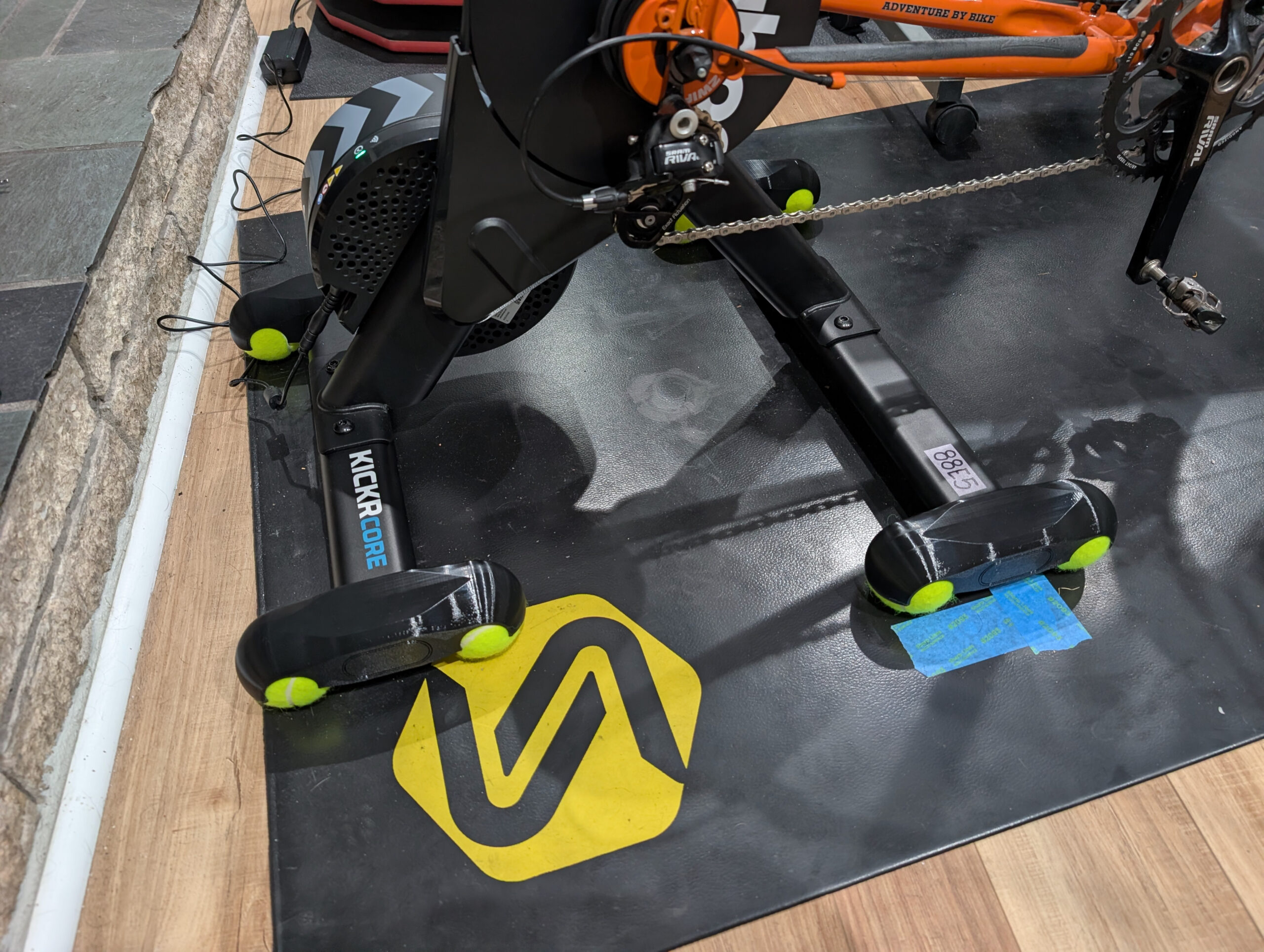
Last winter, after getting a Wahoo KICKR CORE 2 trainer and designing some variable height feet to level the bike I kept thinking about tennis ball feet. These provide a bit of give, allowing the trainer to rock and pitch a bit, reportedly making it more comfortable to ride. (And yes, for some reason I sat on this post for half a year before finishing it up.)
I’ve never really noticed an issue with the static positioning of any of my trainers, but Kristen purchased a KOM Cycling Indoor Rocker Plate RPV1 while getting ready for AIDS/LifeCycle in 2021/2022 and now finds she can’t really ride indoors without it. Her experience, and hearing nice things about tennis ball feet from others, has made me wonder how something similar might be for me.
There’s a whole bunch of tennis ball feet available for trainers. From the well-engineered ones that my friend Jake / Cycl3dCo makes and sells to a bunch of free designs on Printables and MakerWorld, there’s… a lot of options. Mostly because I couldn’t find one that was low enough profile to not require a riser block for the front tire (the inverse of the problem which prompted my trainer foot design), a bit of late-December poor weather boredom, wanting to get better at drawing stuff, and perhaps a bit of NIH, I decided to try designing my own.
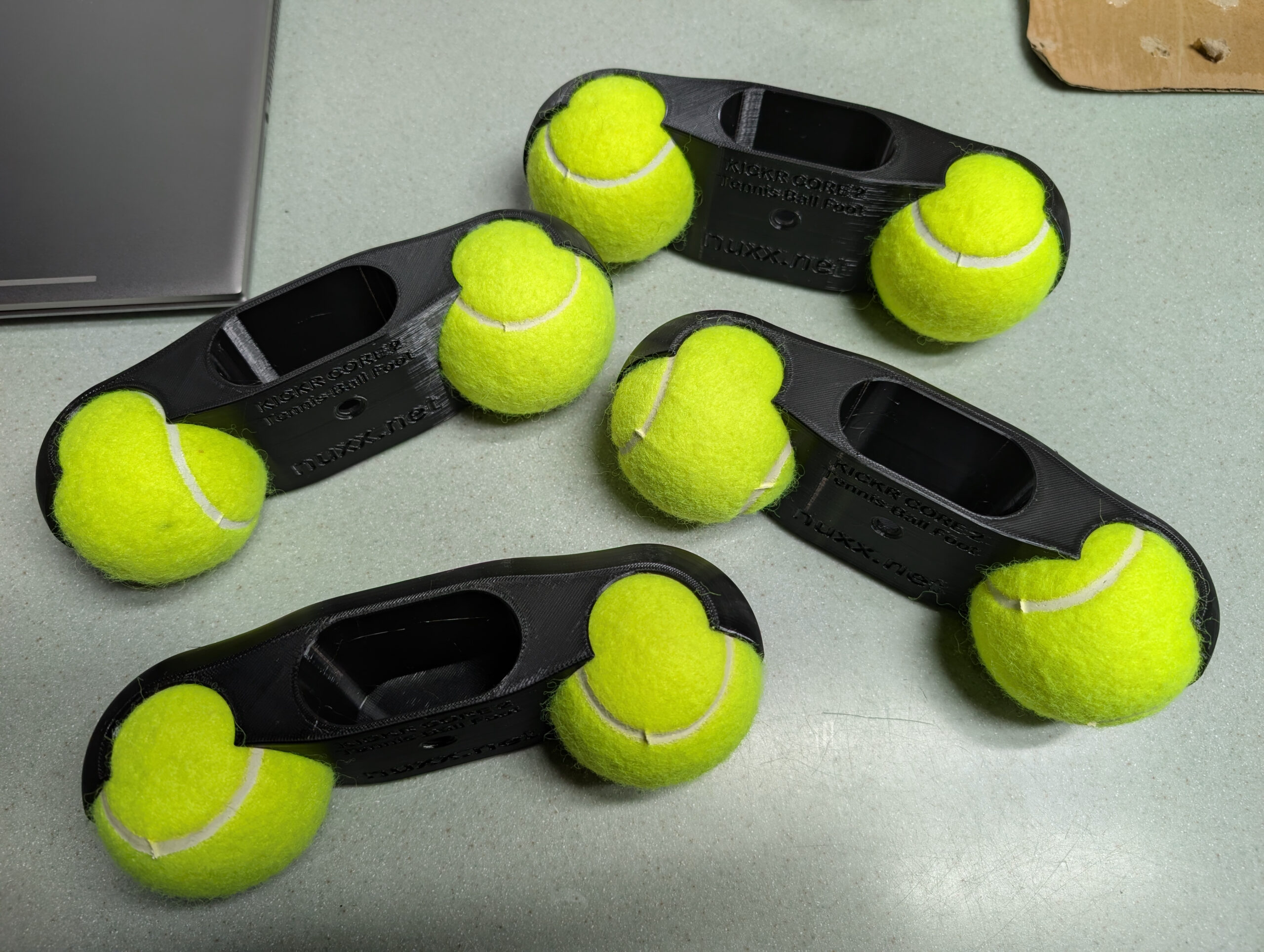
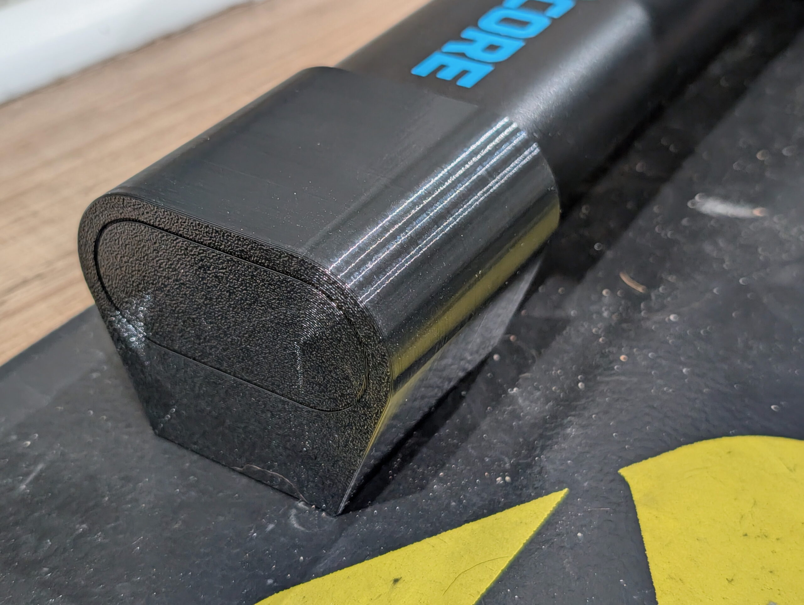
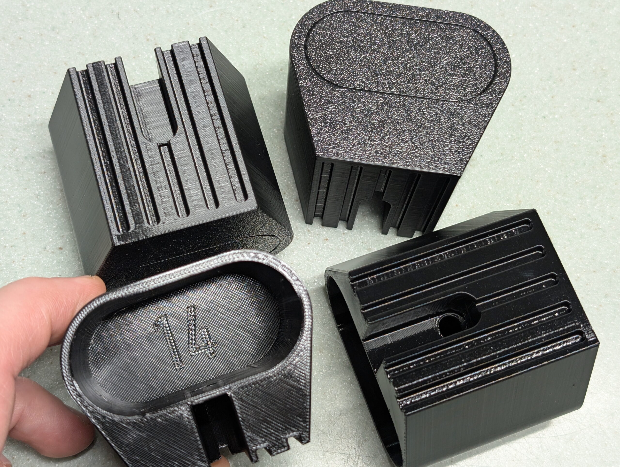
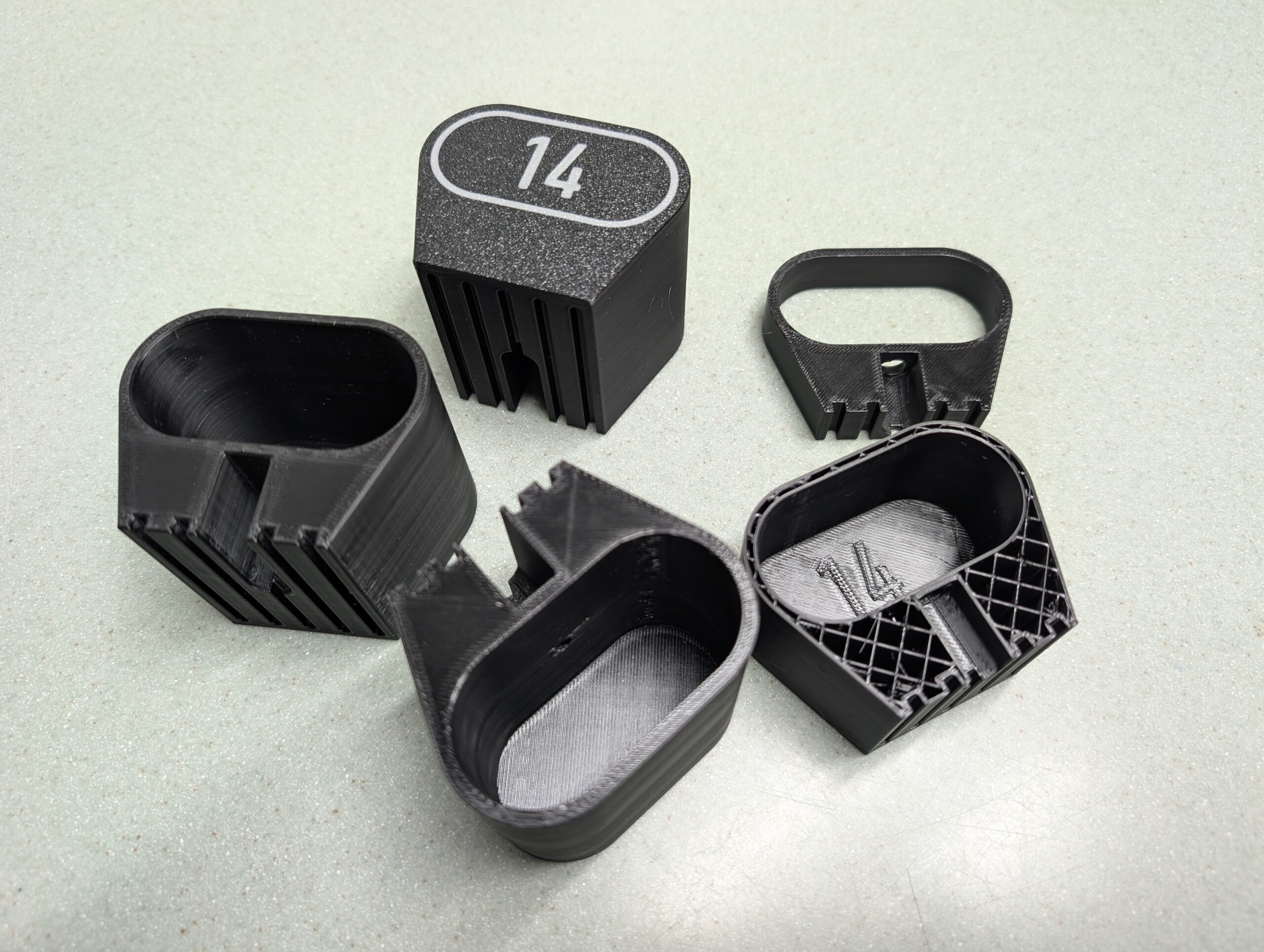
Detail of four of my KICKR CORE 2 low profile tennis ball rocker feet.
Here’s what I came up with. These are yet-another-set-of tennis ball feet, but they are designed so that with a 700c x 32mm front tire on the bike the axles are level during riding, and they replace the stock rubber feet and are held in place with the original retention screws.
I restarted this design numerous times over a few days and learned a lot about constraints and what not to do. I was originally going to make this a parametric design like the variable height feet, but realized it’s not as useful and stuck to a single height. This also allowed me to take some shortcuts in constraining drawings… Not the best practice, but not horrible for what I was doing.
The final items were printed using the same filament and profile as the Riser Feet (Overture PETG in black, 6 walls, 25% gyroid infill, printed hot and very slow), and they came out nicely. Because of the quantity of filament needed (estimated ~529g) I started on one spool and used the AMS to auto-swap to the second when the first ran out. I was a bit nervous about how this would go, but it ended up working out wonderfully. While the second spool, purchased about two month after the first, had a more matte look to it, but it looked good once melted and deposited. My concerns about print imperfections during the swap ended up being for naught.
A very slow print job. This took ~34 hours.
I’m fairly certain I both designed and printed these more robustly (and slowly) than is needed, but as a beginner I’d rather err on the side of overbuilt (and spending a bit more on plastic) than have something which breaks and interrupts a ride.
Included are .f3d, .step, .stl, and Bambu Studio.3mf files. The .3mf is as I printed it, including the print profile and imported .step files. (The .stl from Fusion, even exported at the High setting, end up lower resolution than I prefer, but was included for completeness.)
So how do they it feel to ride? Well, to be honest, they did what I thought they would and added some flex and give. But I’m not completely sure I like it. Just before spring I went back to my previous self-designed riser feet. Next winter I’ll give these another go, though.
A big, big thanks to Jake for providing a bunch of help and suggestions. He has a ton of experience designing parts professionally and printing them for both prototype work and production and he shared a bunch of tips, tricks, and information that got me pointed in the right direction for this and many other designs.
If you are looking to buy some tennis ball feet or other Michigan-made accessories for your trainer, give Jake your business over at Cycle3dCo.
(As I was finishing up my design and waiting on a test print, I came across Kickr Core 2 Rocker Feet for tennisballs by punkti over at MakerWorld. A quick measure showed they have basically the same vertical as my feet, are physically narrower, but thicker. These likely would have sufficed and use roughly the same amount of filament, but I was nearly ready to do a final print when I found these, wanted to give my own design a try, didn’t really care for the appearance. These do look like a nice option, though.)
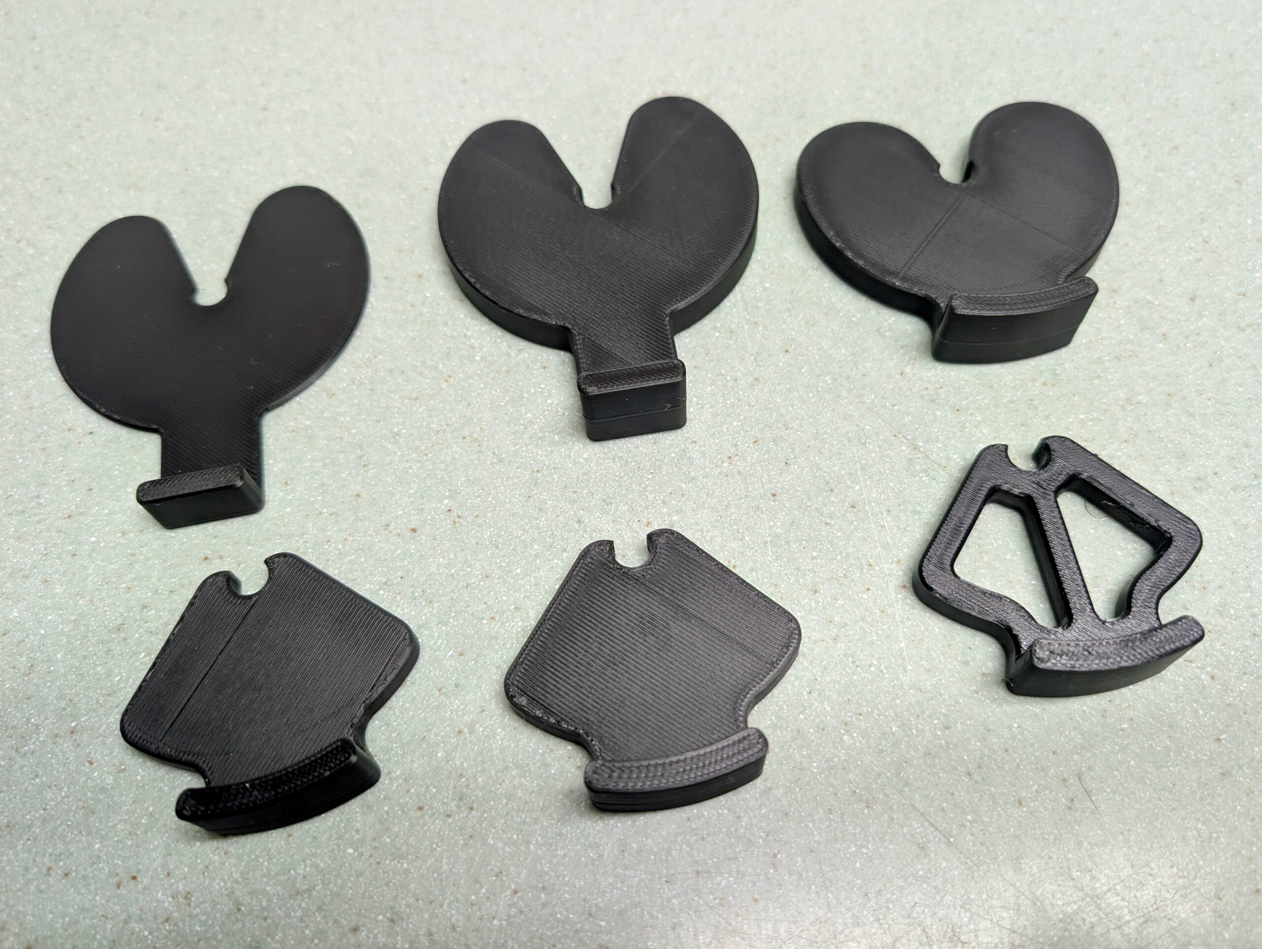
Six iterations, from initial to final, of slip-fit stove knob lockouts.
Even for a few-hour project, I find it interesting to look back at the various iterations of developing something. In this case it’s six different versions of a slip-fit shim that latches on to our stove’s knob shafts, preventing them from being pressed in turning the gas on or igniting. Kristen wanted these to help avoid accidental knob turns (from people, dogs, etc) and being stuck inside by extremely poor quality air from wildfires, it was today’s after-work pass-time.
I’m happy with where the idea ended up. My original idea was for something that pushed in from the bottom and clipped in place, but because of the D shaped knob shaft I ended up with something that’s slipped in horizontally, and as it falls/is turned to a natural position with the tab down, it sticks in place. Along the way I screwed up the thickness, tried making things smaller, then smaller still, then had to nudge the thickness, and then finally cut out a bunch of the inside to use less plastic.
The first five were prototyped in PLA, and for the final items I printed them in PETG. Although I think the plastic might have been a bit damp as it was stringy… Still, it was easy enough to clean up and fine for this.
The models can be found here on Printables, if you’re interested. Or I’ve got a simple demonstration video of it here.
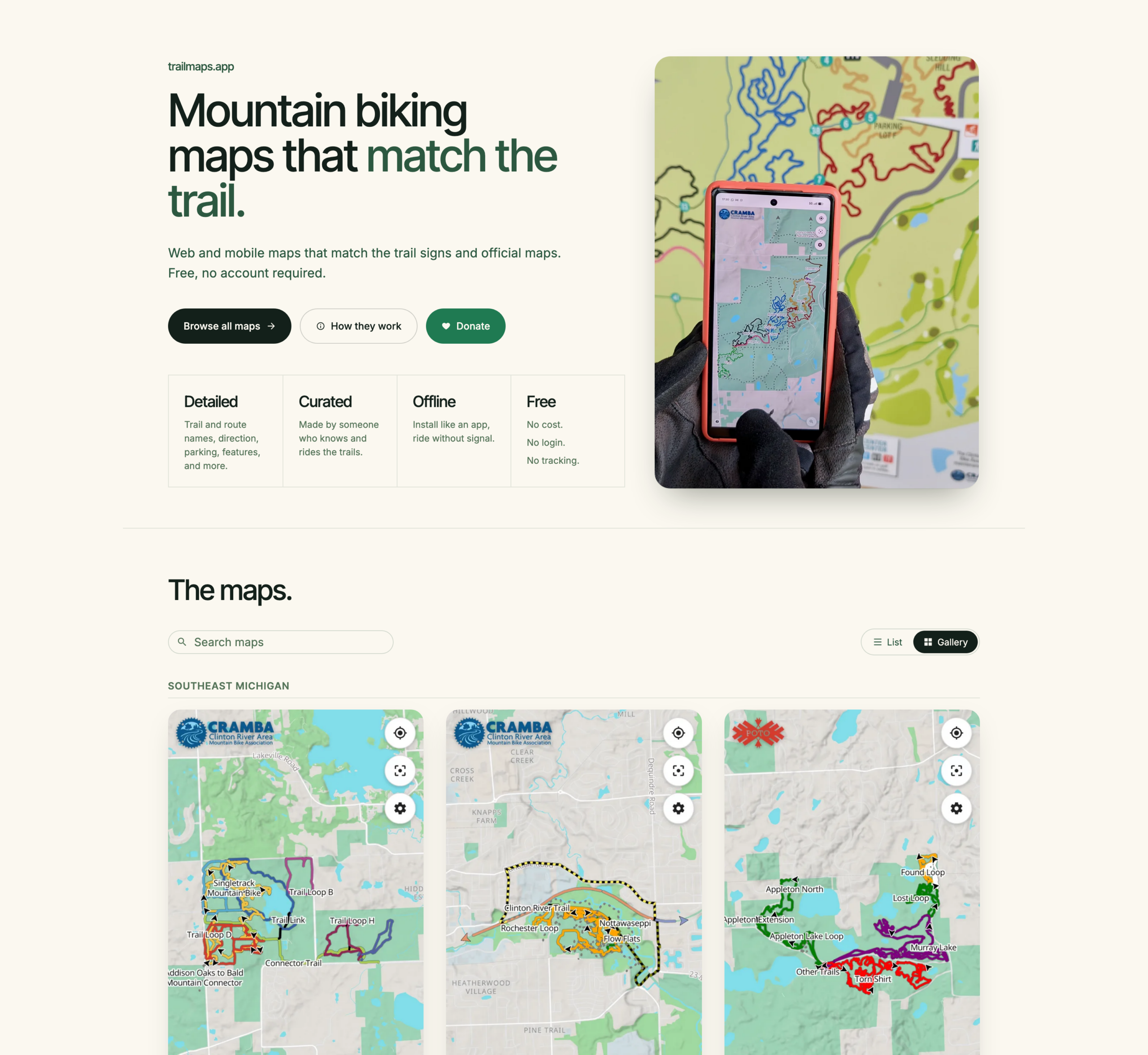
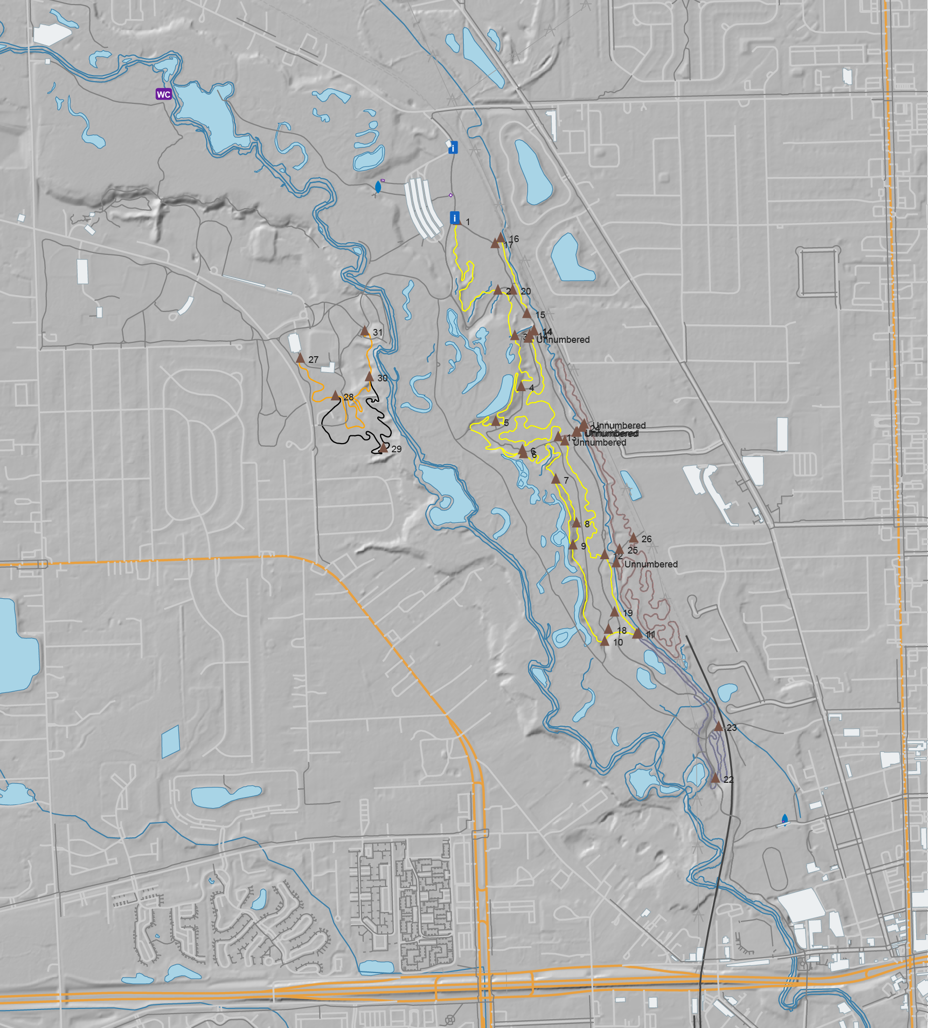
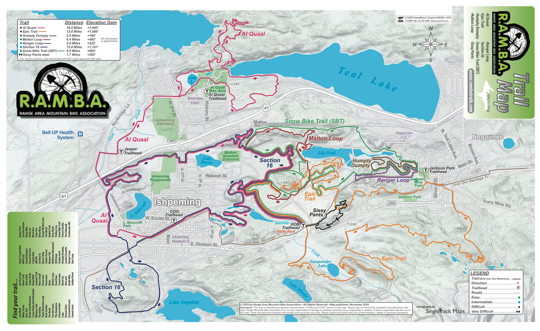
I’ve been using it for a while now, so I guess it’s a good time to announce the revamp / relaunch / whatever of trailmaps.app. This is a personal project website which started one frosty January morning as I sat in an Ishpeming rental waiting for temps to rise before heading out on a fatbike ride and is now a hub for hosting maps I’ve generated of various trail systems.
The root of the idea was cooked up on a long drive; I wanted something akin to the subway-map-style’d official RAMBA print map (parallel lines over a single trail to illustrate the trail’s membership in multiple routes), but web based. And maybe usable on a phone. And after the early learning then quite a bit of work this spring… Here it is.
Instead of just doing a single map (one-map-at-a-time coding / tile generation / etc) as I had in the past, I now have a full-on map generator that takes data from OSM and other online/open/free sources, combines it all, and generates static content that’s easy to host and cachable so it works if a device loses cell service. It’s basically as close to an app as one can get while still staying web-based.
By being hand-curated (that is, not just auto-generated off of all OSM data) these maps also fill a long-standing gap with other online maps (eg: Trailforks, MTB Project, Strava, RideWithGPS) in that they don’t style (color) the routes the way official park maps and signage do, making what a rider sees on their phone challenging to align with what they see on a signpost next to a trail.
There’s a bunch more features that this brought about, which I won’t dive into as much depth, but which I’m still quite proud / happy with. The end results are what I want in maps, and it’s nicely reusable:
Reusable map generation engine; I write a YAML description of the map (title, OSM references, info that can’t be found in OSM) and it makes the map. If the engine or data gets updated, re-run the map and/or website generation tools.
PWA (Progressive Web Apps), so they are installable app-ish, but without the app store overhead.
OSM data is not fetched live — it’s a snapshot taken map-generation time — meaning errant edits don’t break the map.
Zero user/usage tracking, including having all assets loaded from trailmaps.app. (I’m trying to support less and less online tracking while still providing a good tool.)
Ability to generate maps custom from non-OSM data, such as race or group ride routes.
Thorough, proper (read: non-shady) SEO such as OpenGraph previews and metadata, making link embedding, sharing, and site discovery by search engines work well.
Hostable for cheap since the only server requirements are TLS and RANGE requests. A $5/mo Nanode from Akamai (formerly Linode) easily does it all.
Stand-alone maps (each map is a self-contained site) makes it possible for them to be hosted elsewhere, such as if one was made for a trail club/org, etc.
And yes, I heavily used AI-assisted development for this. It was quite educational as since I knew the inputs and outputs, use the maps myself, and was able to do quite a bit of QA, the result is great. At my day job in IT there is (as typical) a huge emphasis in using AI tooling to assist us with our work. This served as a nights-and-weekends project that was quite educational and will benefit me in day-job stuff while achieving a personal goal of making something I wanted and useful for others. It also illustrated the interesting balance between what AI-generation is good at (code, bug finding) and what it’s not (wording, stylistic choices that aren’t simple clones, avoiding feature bloat).
I’m subsequently making the map generator itself available under the MIT license so others can use it. I do have an extensive toolchain for generating the website (takes a definition file and generates the maps, creates preview images, updates the index, rsync’s it to the server) but that part is staying closed / non-released because it’s very my-setup-specific.
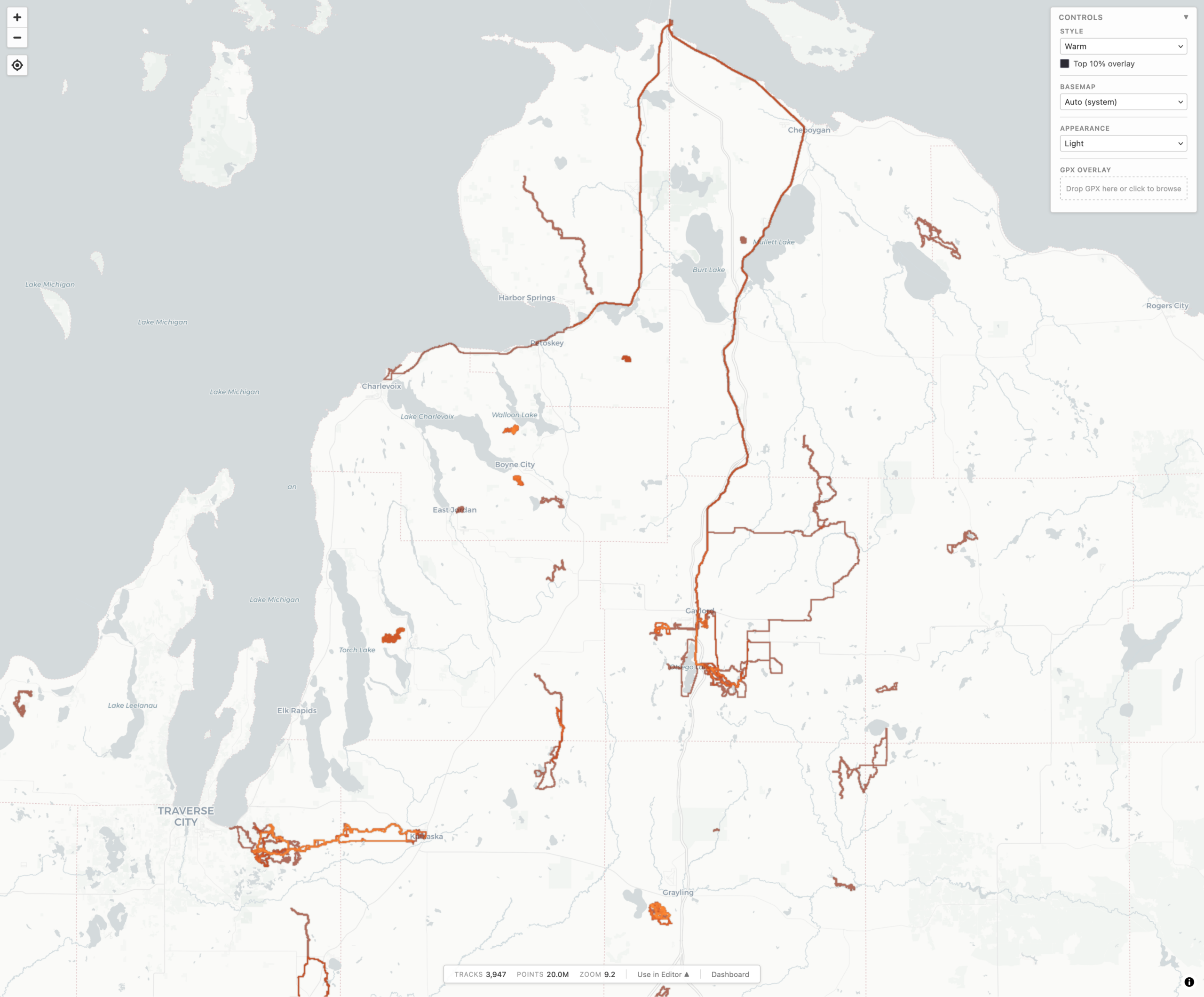
local-heatmap-tile-server v1 showing Northern Michigan in Warm style and Light appearance.
During a long drive to (and from) Florida, and a lot of thinking about maps, I realized something that I really wanted, and something that I could use AI-assisted development to experiment with: generating a heatmap from all my personal, archived activity files. Specifically, generating XYZ tiles, making them available via TMS (so they can be used as an imagery layer in JOSM), and also displaying them on a slippy map.
For years I’ve been using the Strava heatmap as a layer in JOSM for OpenStreetMap (OSM) editing and this works great, but I’m finding myself disconnecting from online social networks, including Strava, more and more. And while the Strava Global heatmap does work as a data layer with a free account, I began thinking about other options to use it, and other cloud providers, less and less. And yes, there’s similar offerings from RideWithGPS and whatnot, but I really wanted to generate my own since it’d give me a lot more flexibility.
So, for my next project working with Claude, I decided to try building a personal heatmap generation tool. And it worked.
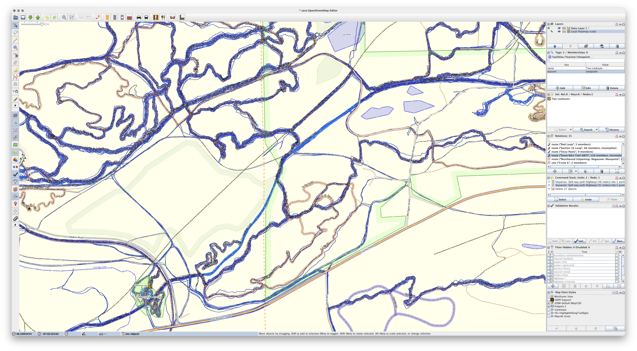
Cool heatmap of my ride and hike data, used as a layer in JOSM. (Ishpeming/Negaunee area.)
Using AI tools to develop software is nothing new, but I’ve never really been one to jump right on brand-new things, instead waiting for them to bake and show their utility before I dig in and use/learn them. I also find it very difficult to learn any tool or system unless I have a way to apply it. But when I do, getting my head around it comes pretty quickly.
In making this I’ve learned / found / finally-realized that with a known set of inputs, a desired output, an ability to identify/recognize bugs, and a task that’s known-possible, AI-assisted development saves can save incredible amount of time. Within reason it makes it possible for me to be more of a product manager than developer. Since I’m not really a developer (my career is in systems management and troubleshooting), that work for me is slow… and I’m not good at it.
Using Claude on the desktop to write the code, VS Code to read and make a few manual edits, and Docker Desktop so I could keep an eye on things, after about a week of free-time iterating, this is what I came up with, and I’m quite pleased:
This is a single Docker container that uses a bunch of Python to import GPS data files (.FIT, .GPX, .TCX), imports, deduplicates, and renders a complete set of XYZ tiles. It then makes them available via HTTP (for display in a slippy map or something like JOSM) or exports them to a PMTiles file for simple hosting. And it has a built-in slippy map viewer/data manager and a couple bundled viewers for completely static hosting (example).
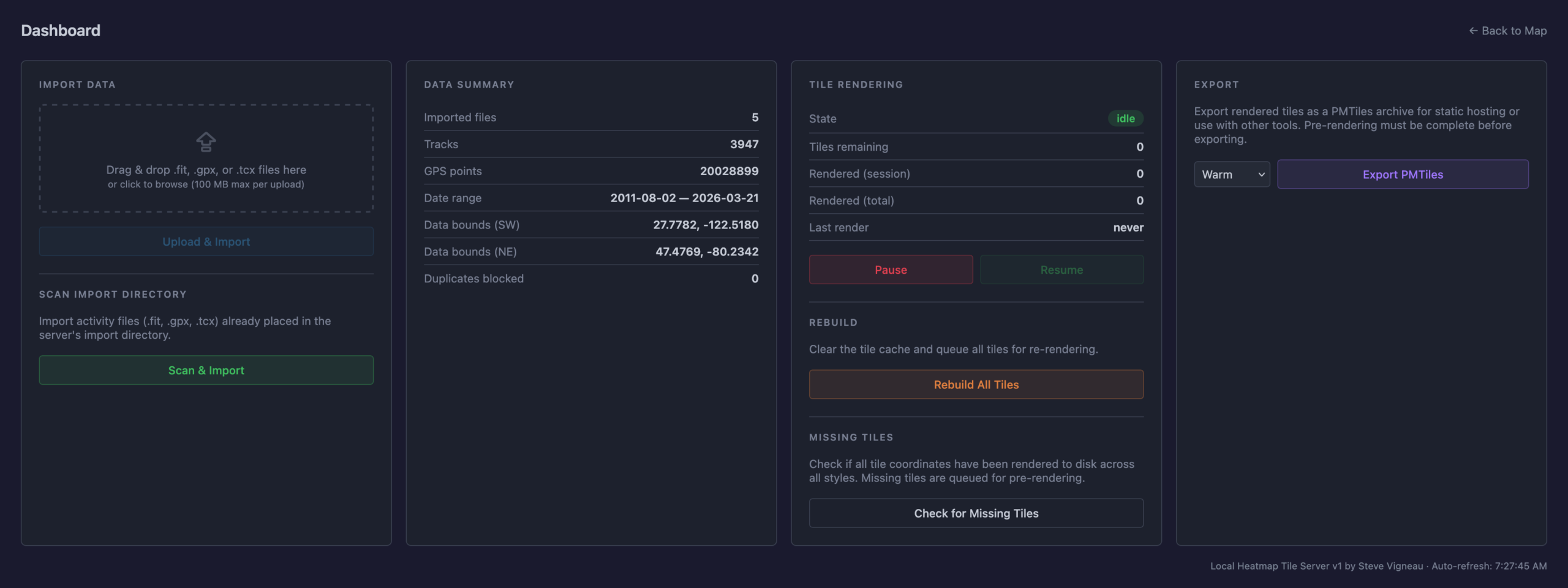
Dashboard for importing new files, stats, and exporting the heatmap for static use.
The Python webserver, uvicorn, isn’t the fastest nor great at caching, so the XYZ tiles are fronted with nginx to very quickly serve them from disk, only passing the request back to uvicorn and the Python stack for rendering if the tile isn’t present. Once the tiles are rendered they are cached very quickly served up solely by nginx, to the point where panning and zooming freely is seamless. (And yes, you can pre-render all tiles for optimal performance.)
It’s been tested on ~4000 track single-GPX files (exported from rubiTrack), ~4000 .FIT files directly from Garmin devices, and a bunch of different types of single GPX files. And… it seems to work!
The file inputs (FIT, TCX, GPX) aren’t special and parsers have existed for a long time. Nothing about heatmaps is new. Tile rendering isn’t new. Tile serving isn’t new. Nor are web-based heatmaps from fitness tracker data. But it needed to be glued together to get something that works this way, and this type of development made it possible. And I learned something new about AI-assisted software development along the way. It’s sure an interesting new world with these tools.
And yes, beyond thinking about the features I had to do a lot of nudging along the way.
Some major bugs that were encountered were getting cross-tile heatmap brightness correct, missing cross-tile data, tiles not rendering properly when called via different ways, moving to a faster web server so panning the map felt smooth, and a whole lot of tweaking of brightness and line thickness and blur and such at different zoom levels so it’d feel nice to use, noticing and dealing with malformed XML in GPXs…
But this was nudging via prompts and having a bit of an idea what it was doing, not coding. Which is what’s so weird and new to me. It’s like directing a team of pretty-decent junior devs.
And the end result is something I’ve wanted for a while. And now it exists. (And no, none of this post was written by any AI tool.)
River Bends Park OSM data, with DEM hillshade layer, ready for Adobe Illustrator
After a bunch of years I’ve updated my MTB trail mapping workflow with a much-improved tool for getting OpenStreetMap (OSM) data into Adobe Illustrator. I’ve been experimenting with AI development tools, and I’ve been looking for projects, and this one fit the bill.
My old workflow used osm2ai.pl, a rather crude script (which I found years ago) that’d take an OSM file and turn it into vectors that I’d then group and style in Illustrator. While the tool claimed to filter objects into layers, I never got this working right, so there was a lot of manual work before I could begin styling the map. Each map took a couple of hours solely selecting, joining, grouping, and deleting stuff.
With some time on my hands during a mountain biking trip I began prompting Claude Code, via Visual Studio Code, for something similar: a tool which would take OSM data and make it usable in Illustrator. After a bit of back and forth I ended up with this: c0nsumer/osm_to_ai.
I very intentionally had Claude write everything on this, from the script to the readme, and it seems to have been a success. A bit of experience was gained, and I now have a tool that’ll read in OSM data (either exported from tools or queried live) and produce an Illustrator-compatible SVG that has trails grouped by OSM tag, colored, etc. All ready to finish up in Illustrator. It even has an extra layer of USGS 3DEP hillshade data, something I’ve wanted for years after seeing it on the Noquemanon Trails Network maps (but didn’t know how to do in Illustrator).
This was both a good exercise in using AI tools to assist in simple software development and helped streamline my mapping process. While I have a general discomfort with AI-developed code ending up with potentially uncertain output, this output is immediately validated visually, so it’s fine.
Unplanned, but on quick check this seems to have the side-effect of being compatible with Affinity Designer. While this wasn’t (yet) an intention, I’ve been looking for a good way to move away from Illustrator due to software cost (this is volunteer stuff, after all) but the old osm2ai.pl needed replacing before I could do that. This will make that possible.
So what next? Maybe I’ll see if I can make the PDF maps geospatial. This has long been a goal of mine, as it’d allow my maps to be opened in something like Avenza Maps and they’d show one’s actual location on the trail. But for now, I’ll start here.
As an overview, here’s the --help output to show what it can do:
(venv) PS C:\Users\svigneau\Desktop\OSMtoAI> python .\osm_to_ai.py --help
usage: osm_to_ai.py [-h] (--file PATH | --bbox BBOX | --overpass FILE) --output PATH [--width PX] [--dem PATH] [--fetch-dem] [--dem-resolution METERS] [--sun-azimuth DEGREES]
                    [--sun-altitude DEGREES] [--save-osm PATH]

Convert OSM data to an Adobe Illustrator-compatible layered SVG.

options:
  -h, --help            show this help message and exit
  --file PATH           .osm file to read
  --bbox BBOX           Bounding box: min_lon,min_lat,max_lon,max_lat
  --overpass FILE       File containing an Overpass QL query
  --output PATH         Output .svg file
  --width PX            SVG width in pixels (height is auto-calculated, default: 800)
  --dem PATH            GeoTIFF DEM file to generate a hillshade layer (any CRS)
  --fetch-dem           Download a USGS 3DEP DEM automatically and use it for hillshade. Saves a sidecar .tif next to --output for reuse.
  --dem-resolution METERS
                        Target DEM pixel size in metres for --fetch-dem (default: 3). Use 1 for lidar-quality where available, 3 for 1/9 arc-second, 10 for 1/3 arc-second.
  --sun-azimuth DEGREES
                        Sun azimuth in degrees clockwise from north (default: 315 = NW)
  --sun-altitude DEGREES
                        Sun altitude above horizon in degrees (default: 45)
  --save-osm PATH       Save the downloaded OSM XML to a file for later reuse with --file

Examples:
  python osm_to_ai.py --file mypark.osm --output mypark.svg
  python osm_to_ai.py --bbox "-71.12,42.36,-71.10,42.38" --output mypark.svg
  python osm_to_ai.py --overpass query.overpassql --output mypark.svg
  python osm_to_ai.py --file mypark.osm --dem elevation.tif --output mypark.svg
  python osm_to_ai.py --file mypark.osm --fetch-dem --output mypark.svg
  python osm_to_ai.py --file mypark.osm --fetch-dem --sun-azimuth 270 --sun-altitude 35 --output mypark.svg

(venv) PS C:\Users\svigneau\Desktop\OSMtoAI>
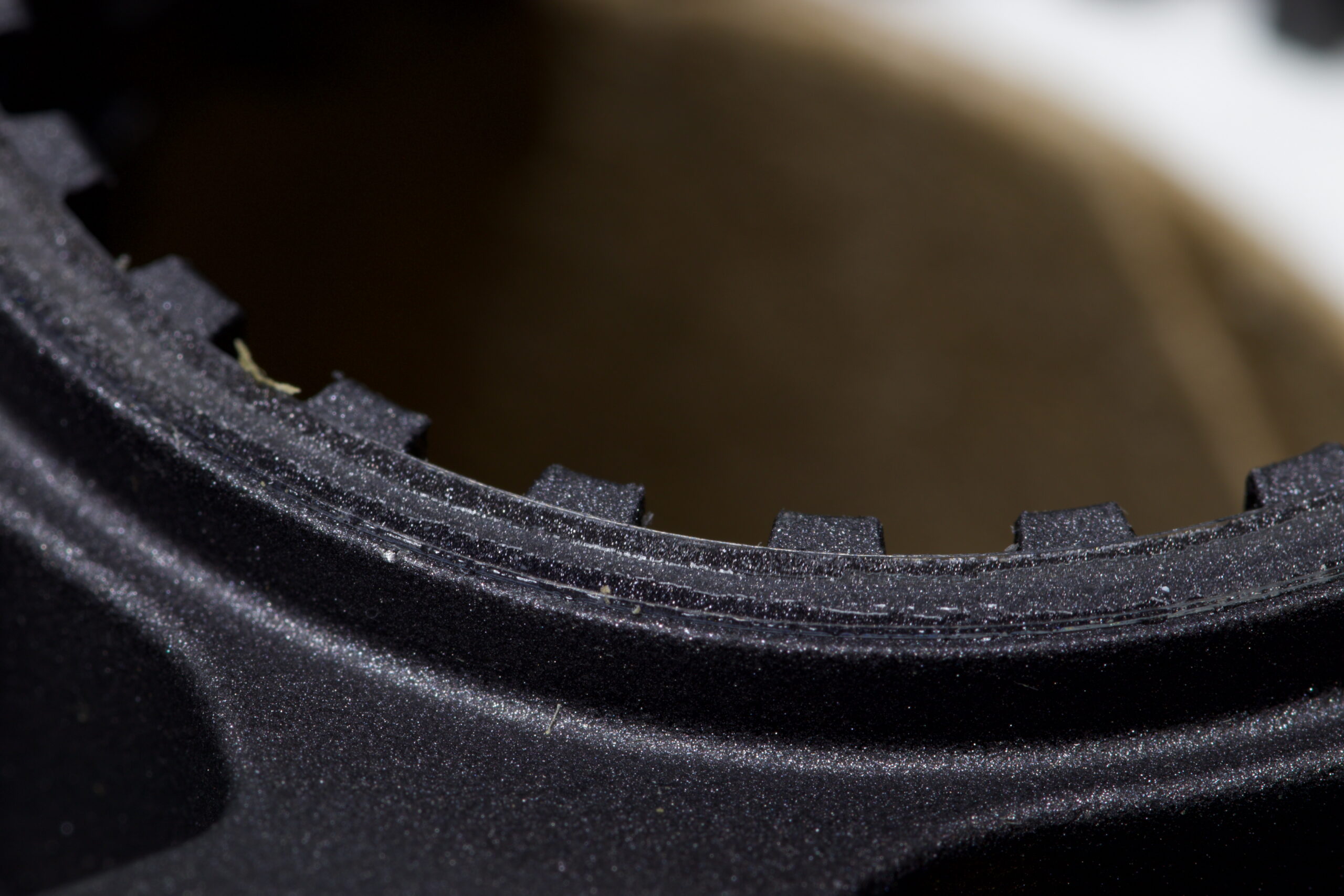
UHMW PE replacement ring applied to a CS-M8100-12 cassette.
Stock Y0GX01500 on a CS-M8100-12 cassette.
Many Shimano cassettes, such as the CS-M8100 (XT, 12 speed) have a thin adhesive ring (part number Y0GX01500) on the back side, where it sits against the Microspline freehub body.
Unfortunately, these can easily be lost as they tend to stay on the freehub body when removing the cassette. Which is exactly what happened when I sent the NOBL wheels from my Mach 4 SL‘s in for a warranty rim replacement. Some folks advocate for removing them, believing them to cause cassette wobble, but the main purpose seems to be eliminating noise and fretting between the cassette and freehub bodies.
Since I don’t like bike noises, I wanted another. They can be bought online for something like $9/ea before shipping, but that seems like a lot… So a better solution? Make one!
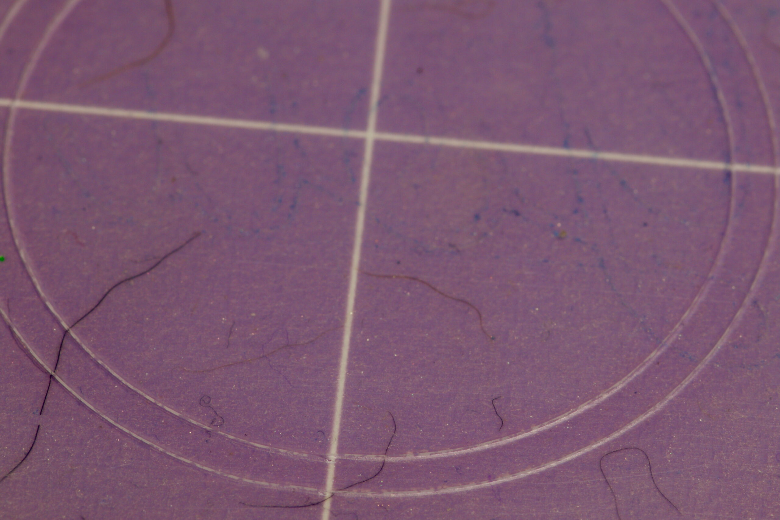
37mm x 33mm ring cut from UHMW PE on a Cricut.
Measuring a new ring on a spare cassette showed it to be 37mm OD x 33m ID, roughly 0.2mm thick. I have some 0.0115″ / ~0.29mm (Ultra High Molecular Weight Polyethylene (UHMW PE) tape from McMaster-Carr (part 76445A764) that I use for rub on bike frames, so that seems perfect. Kristen cut a ring out with her Cricut (with a Deep Point Blade, set to “thin cardboard”), I stuck it to the cassette, and that was that. Much better than spending $9 and waiting for it to arrive.
I had originally tried to print one with PETG filament, but when the first of two broke coming off the build plate I figured it probably wasn’t the right material and would come apart under load, leading to a loose cassette, noise, etc. UHMW PE tape is very malleable and often used to stop noise between rubbing parts, so it seemed like the better choice.
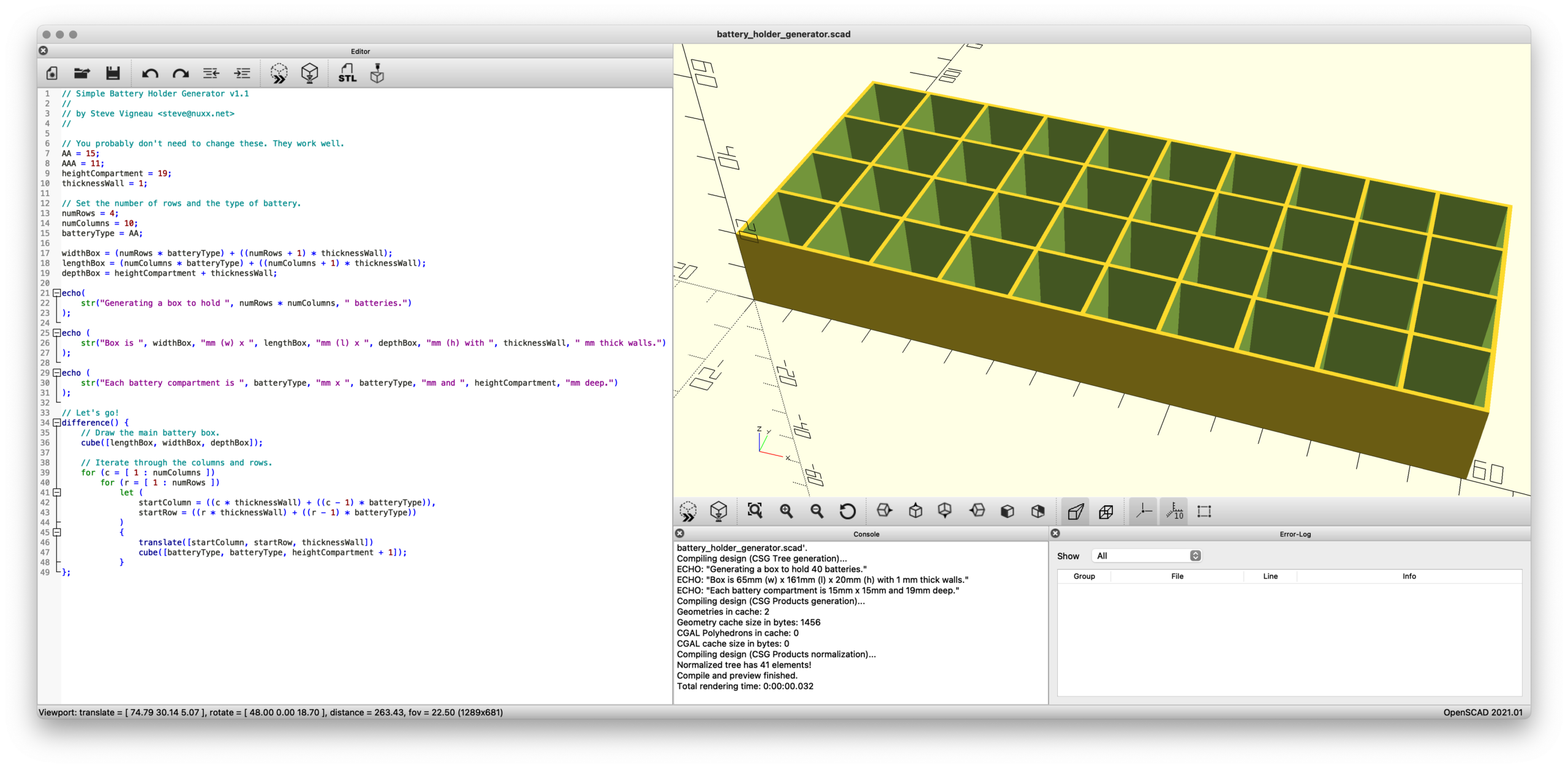
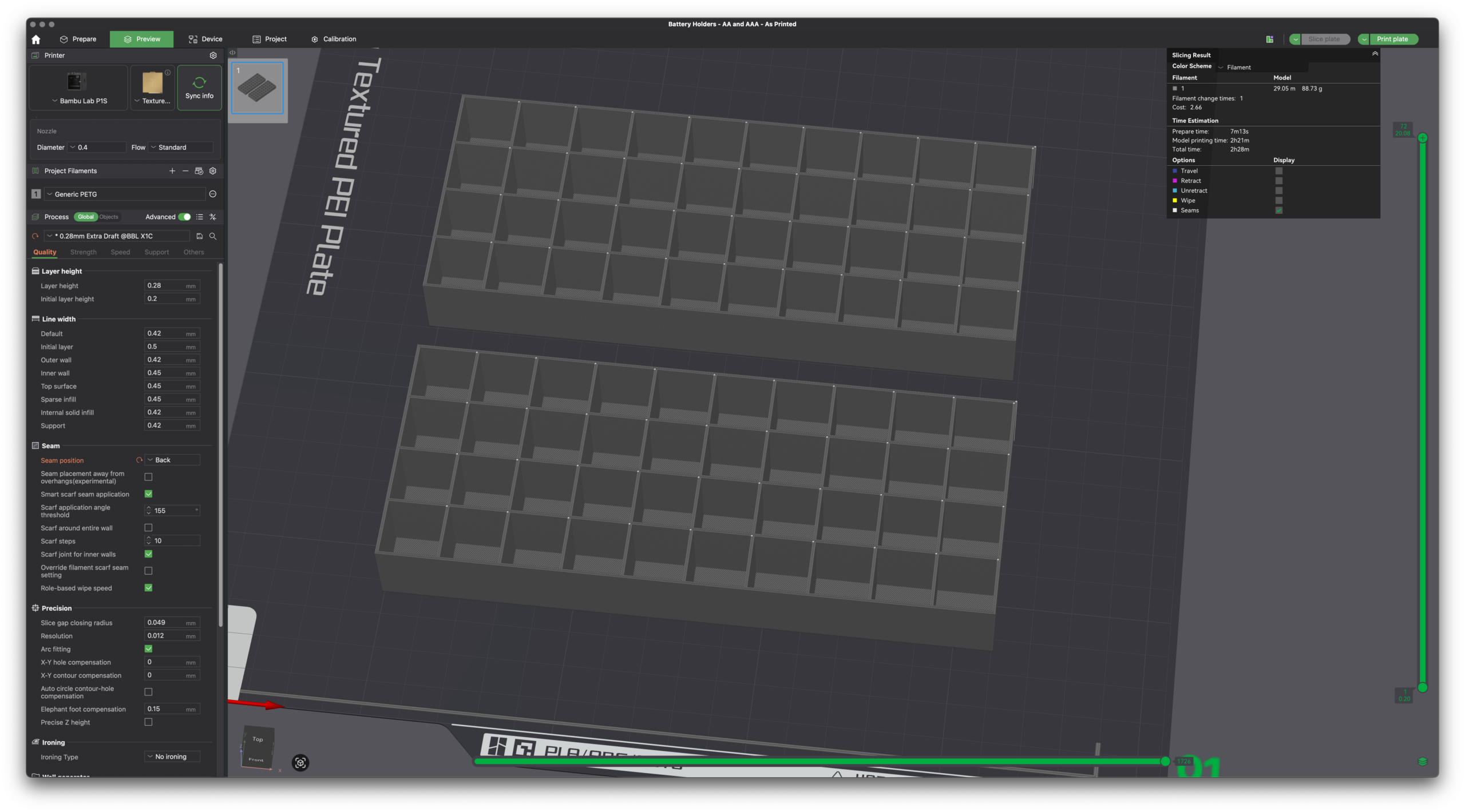
Earlier this year I designed a very basic box/organizer for AA and AAA batteries in Autodesk Fusion, making it parameterized so that by changing a few variables one could adjust the battery type/size, rows/columns, etc. This worked well, and after uploading it to Printables earlier today I realized that reimplementing it would probably be a good way to learn the basics of OpenSCAD.
OpenSCAD is a rather different type of CAD tool, one in which you write code to generate objects. Because my battery holder is very simple (just a box with a pattern of cutouts) and uses input parameters, I figured it’d be a good intro to a new language / tool. And in the future might even be better than firing up Fusion for such simple designs.
Slicer showing the Fusion model on top and OpenSCAD on bottom.
By changing just a few variables — numRows and numColumns and batteryType — one can render a customized battery holder which can then be plopped into a slicer and printed. No heavy/expensive CAD software needed and the output is effectively the same.
Without comments or informative output, this is the meat of the code:
Simply, it draws a box and cuts out the holes. (The first cube() draws the main box, then difference() subtracts the battery holes via the second cube() as their quantity and location (via translate()) is iterated.
That’s it. Pretty neat, eh?
(One part that confused me is how I needed to use let() to define startColumn and startRow inside the loop. I don’t understand this…)
While this probably won’t be very helpful for more complicated designs, I can see this being super useful for bearing drifts, spacers, and other similar simple (yet incredibly useful in real life) geometric shapes.
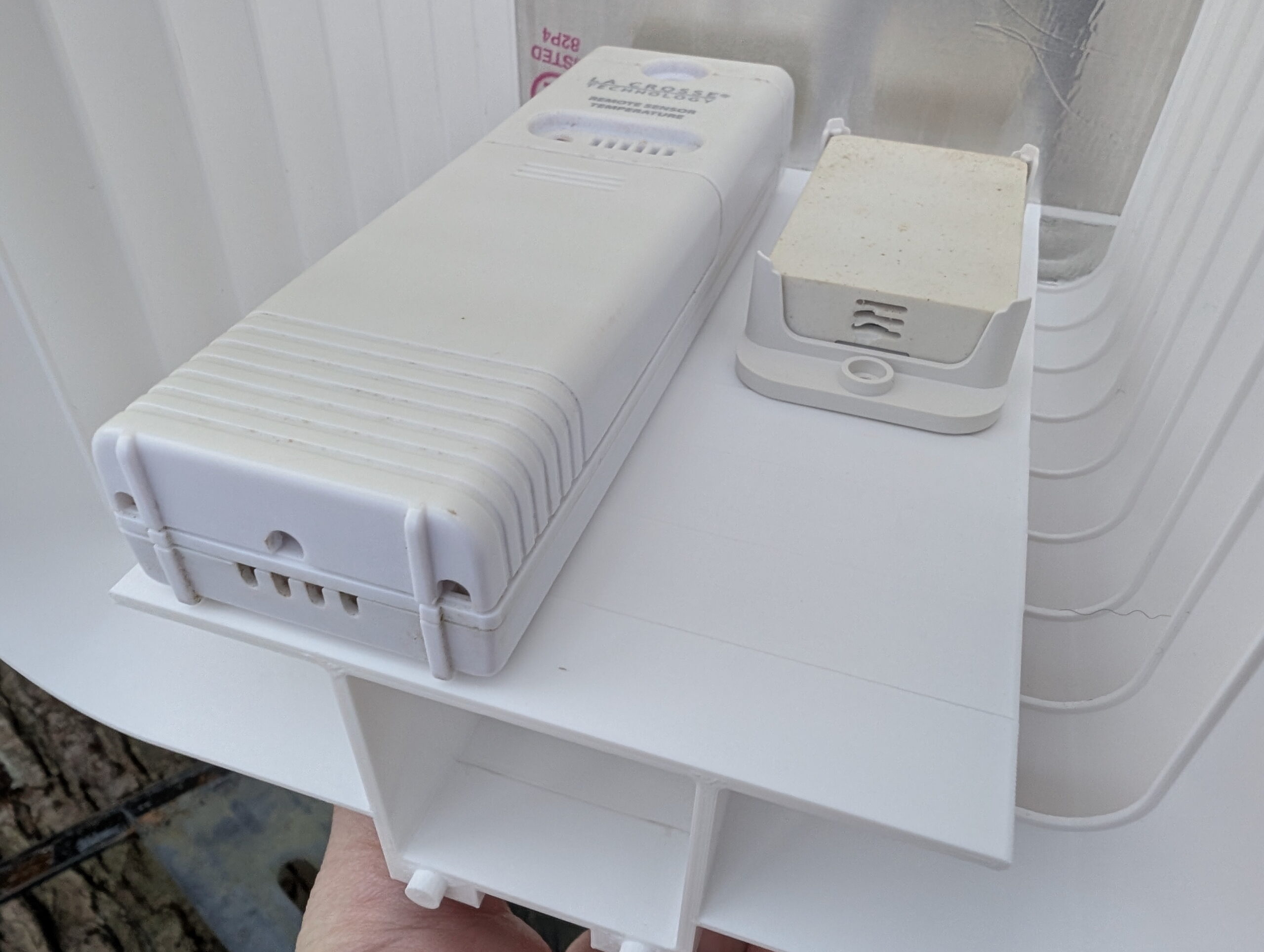
Solar radiation (sun) shield mounted to the chain link fence.
I have temperature/humidity sensors in the back yard, both for Home Assistant and a La Crosse “atomic clock” on the wall of my office. These had been mounted nicely in the shade on a north-facing post on our old wooden fence, but after the fence was replaced I needed to find somewhere else to put them. The first place I tried, the back side of a utility pole, was too close to the fence and they’d read overly-warm in the evenings as the sun was hitting it. (And had the legal issues around mounting things on a utility pole.)
There are myriad different “solar radiation shields” available either for purchase or 3D printing, but they are generally designed to hold one sensor and be mounted on a pole, get held together with bolts, or just aren’t a great design.
I’m really happy with how it came out. In the end it’s a simple two-piece (plus mount) design, with one being the roof and the other a body piece. Each body piece is 15mm tall so I printed off the requisite number to hold my sensors (nine), one roof, and stuck it all together with J-B Weld PlasticBonder epoxy. Pegs and holes align the pieces and make it easy to glue together.
The vents offer shade all the way to horizontal while still having massive openings, so I think it’ll work well. The roof is a bit more translucent than I cared for, but by lining it with some foil tape it’s now nicely opaque. I’m not concerned about the transparency of the vent slots, but may add tape later or re-print with a different filament if it seems to be a problem.
Currently I have La Crosse TX141-BV4 and ZOOZ ZSE44 sensors installed, but may add others as I want to replace the ZSE44 with something that reads negative values. The sensors are held in place using 3M VHB 4910, which is easy to remove (by sawing through with dental floss then rolling off with a finger) but otherwise holds very firmly, especially against shear loads. It’s also thick enough to fit between the ribs on the back of the ZSE44 mount. And I had it on hand.
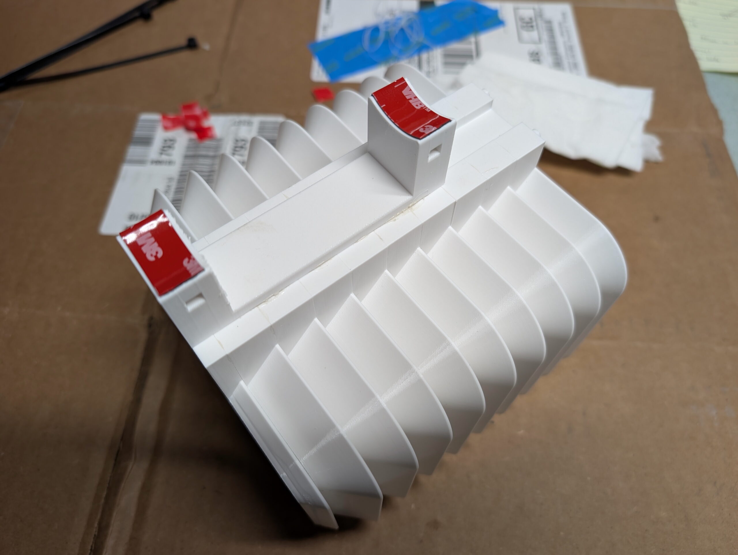
Chain link fence post mount, with VHB 5925 for additional support.
I initially designed this to use QUEEN SIZE BrickClip fasteners and hang it off the north-facing side of the chimney. Due to the weight of the assembled unit with sensors (~350g) and wanting to keep it away from the house’s thermal mass, I designed a chain link fence post mount. This allowed me to place it quite close to where the sensors previously had been, a nicely shaded yet breezy location. The designed-in slot (originally for BrickClips) just happened to allow easy addition of other mounts.
The entire unit was attached to a chain link fence post using black UV-resistant cable ties and with 3M VHB 5925 tape for a bit of additional stability. This tape works well but also was chosen because I had it on hand and it’s nice and thin. While this is a strong adhesive it’s really only needed for a bit of friction to keep the mount from twisting on the pole if bumped.
So how does this one differ from the other designs I came across? Or, differently stated, why did I bother making my own?
Sensor-Agnostic: Flat platform allows any sensor to be stuck in place. Most designs are for a single sensor type.
Larger: Most other designs only hold one sensor. I wanted to hold two or three.
No hardware: Many other designs are held together with bolts. I’m fine with gluing it together as this makes everything else simpler.
Flexible Mounting: A simple 15mm x 5mm notch in the back both allows BrickClip fasteners to be used while also a simple platform for integrating other mounts (such as the chain link fence mount).
Full Body Support / No Arm: Many other mounts replicate the shield-on-an-arm design of commercial pole mounts. I am concerned about FDM printed thermoplastic sagging, so either this needed to be metal, or the support done differently. I also had no need for a pole mount.
+14mm custom-made riser foot on my Wahoo KICKR CORE 2.
The Problem and Solution
My new trainer, a Wahoo KICKR CORE 2, has the rear axle that’s ~322mm above the floor. With anything larger than a 700c x 25mm front tire this puts the front wheel higher off the ground, which screws with the bike’s geometry including the all-important saddle position. After a bit of measuring I found that raising the trainer ~14mm would make things level on our floor, and having a 3D printer and a wee bit of design skill, I decided to make replacement feet that’d put it at the height I wanted.
This is the result, 3D printable feet which replace the stock rubber ones, securing in place with the same set screws, and can be printed in whichever height is needed.
Final prints of the four riser feet for my trainer.
You can find the .STL files for +5mm to +50mm in 5mm steps, a Bambu Studio project containing all the sizes, and a parametric Autodesk Fusion project allowing you to generate your own custom height riser feet. (Just change liftAdditional.)
This is all licensed CC BY-NC so one can make them, change the design, whichever… You just can’t sell them:
(If you really do want to sell them, email me and we’ll work something out.)
These printed wonderfully using Overture PETG at slow print speeds (50mm/sec) in a Bambu Lab P1S with all fans off and temperatures on the high end of the specified ranges. (I am curious how TPU would work out for printing these as it should be more rubber-like…)
Design Lessons
Development prints, including tests of screw hole size and size indicator types.
The main point of this post is to document a few things I learned while designing this. Big, big thanks to my friend Jake Drews — who sells a number of similar products on Etsy as Cycl3dCo — for talking through some design ideas with me.
So what did I learn?
I wanted to have parametric text on the bottom of the printed surface to show the lift. After experimenting with a second color for style and indication — which was not a great way to go — I settled on using a groove for design, and wanted a single line font as a similar groove. (These print well, akin to a 45° chamfer.) It turns out that single line fonts in Fusion need to be exploded before they can be swept to make a groove. Exploding a font makes it no-longer parametrically controlled.
The simpler solution ended up being putting the height inside the leg as 0.5mm raised text, sized to sit inside the tube of the leg, and leaving the groove on the outside as a decorative feature. After all, one doesn’t need to see the height all the time, but it is good to have the parts marked. This works out better all around. Leaving the end just blank looked boring.
If you can avoid multi-color printing, it’s probably better, as it’s less wasteful, many people don’t have multi-color printing setups, etc.
Adding an inset of 0.01mm will make it easy to color in the slicer (OrcaSlicer or Bambu Studio), but if not colored, is small enough that it’ll be ignored by the slicer. This is a good way to make optionally-multi-colored designs. (Note that my final design didn’t use this, but it’s a good-to-remember technique.)
New trainers?
A few months back there was a great sale on the Wahoo KICKR CORE 2 trainers, and while Kristen and I had some problems with Wahoo in the past, the price was low and the new features would solve some problems, so we both decided to buy them. Specifically:
Wi-Fi Connection / Kickr BRIDGE: Kristen and I both use an Apple TV (ATV) for Zwift, and the number of Bluetooth (BT) connections on the ATV is limited to two. This meant we could use Trainer + Cadence, or Trainer + Heart Rate Sensor (HR), or Trainer + AirPods. All very limiting. With the CORE 2 it can communicate via Wi-Fi and also bundle the HR data in, freeing up the ATV’s BT channels for other things, such as the Zwift Click controllers and AirPods. It also feels more reliable, and has been very nice.
Virtual Shifting / Zwift Cog and Click: Via smart use of the smart trainer features, the CORE 2 supports virtual shifting with a single cassette cog. This eliminates wear on more expensive drivetrain parts (cassette), makes it easier to take the bike on and off, and results in a near-perfect chainline so things are simply quiet. While it took me a few rides to get accustomed to virtual shifting, it’s pretty nice and feels similar to actual shifting steps, but without the noise or wear.
Noise: Simply put, the CORE 2 with the Zwift Cog is quiet. Unlike her older CyclOps Hammer, I can’t hear her riding. This might not sound like much, but the Hammer had a steady whine that I could hear throughout the house. It’s pretty much only the rattle of the chain passing over the cogs and noise from the blower fans.
Weight/Balance: Kristen uses her trainer on a KOM Cycling Indoor Rocker Plate RPV1. With the older Hammer it’s heavy, asymmetric design made the whole assembly list to one side unless she put a 15 pound weight on the rocker plate opposite the trainer. The CORE 2 is more symmetric and lighter and simply doesn’t have this problem.
All around, they worked out to be nice upgrades, and we were able to easily sell our older trainers for fair prices. For a bunch of details on these trainers give this DC Rainmaker review a read.


