nuxx.net
Making, baking, and (un-)breaking things in Southeast Michigan.

Category electronics

SIDbox… Goes Somewhere…


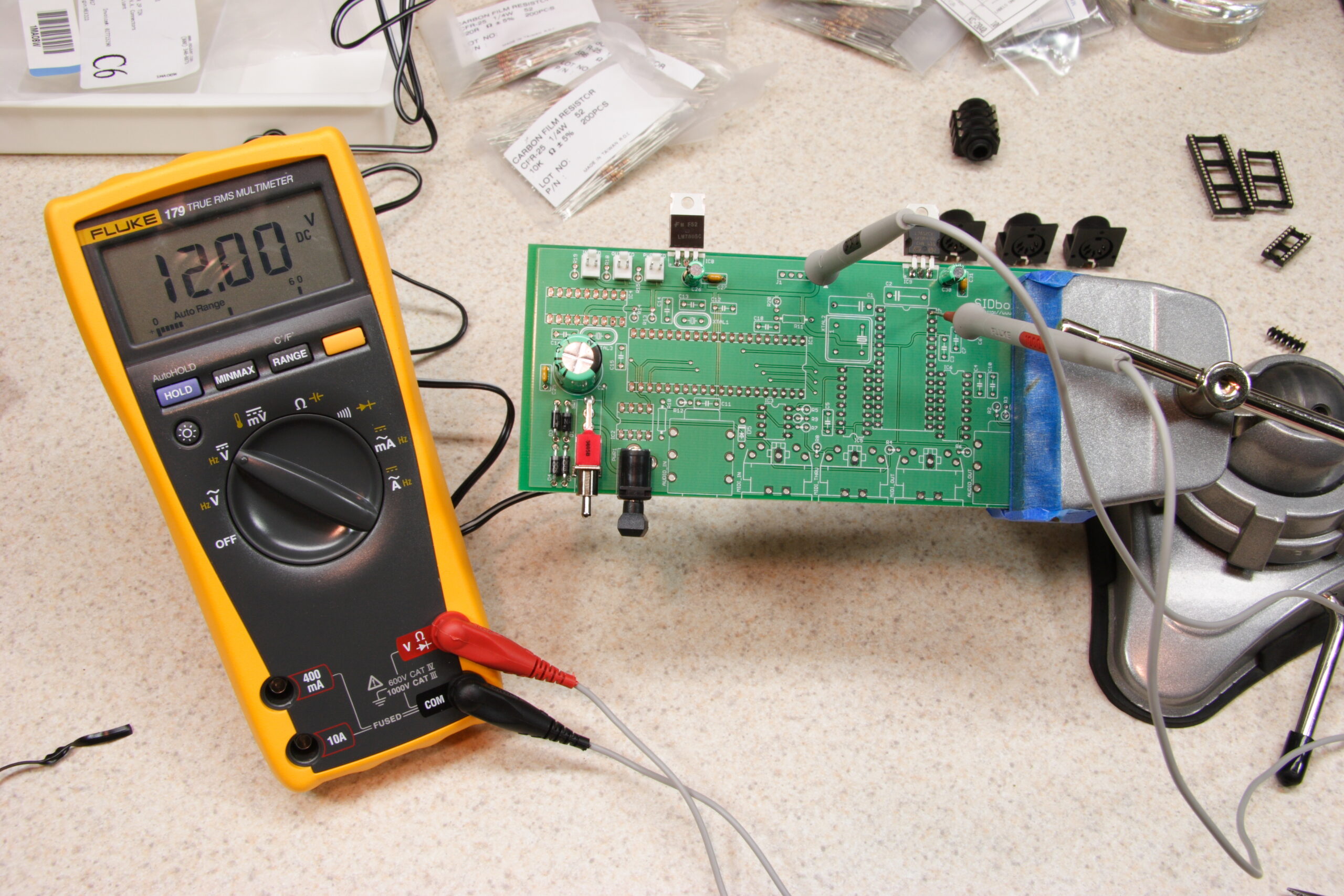
Well, power works.
(Click for more SIDbox photos…)

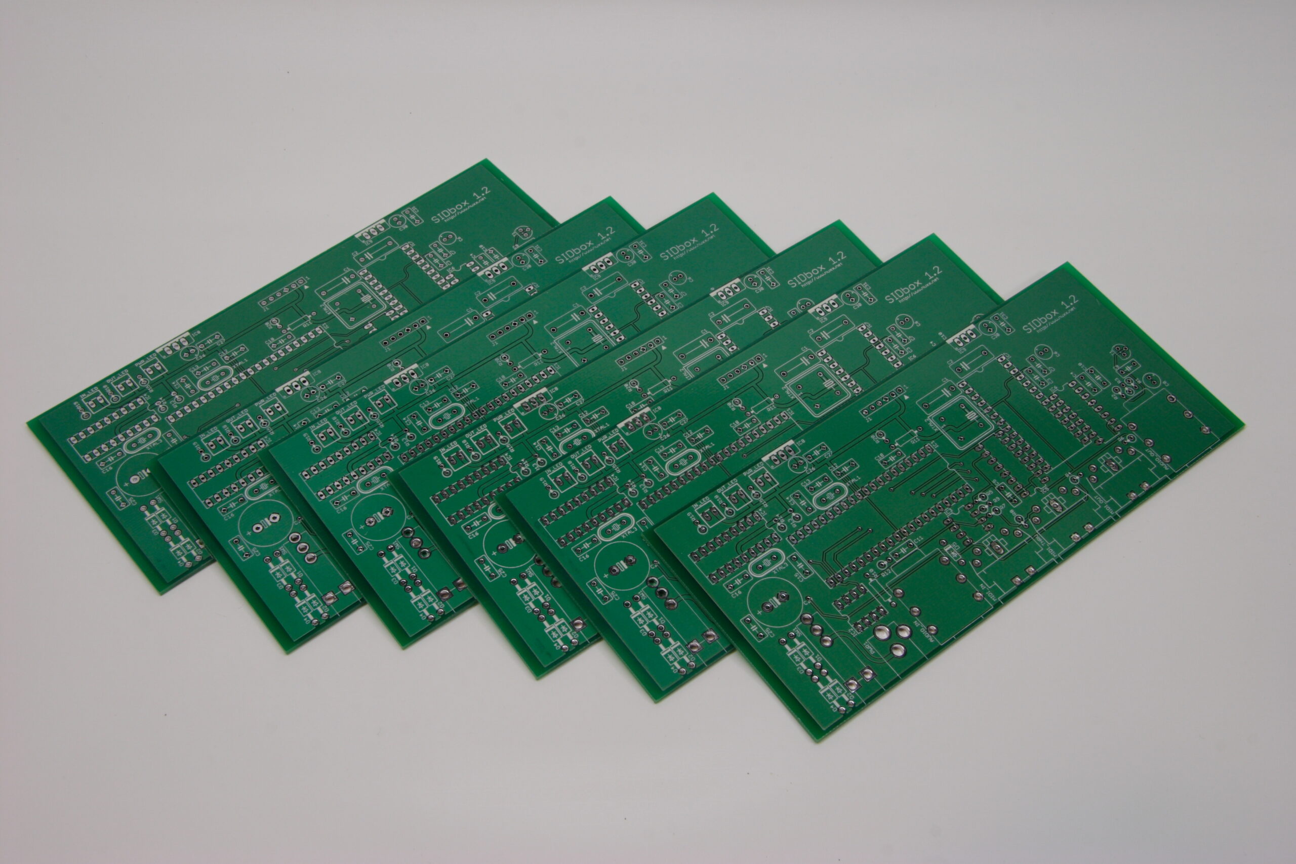
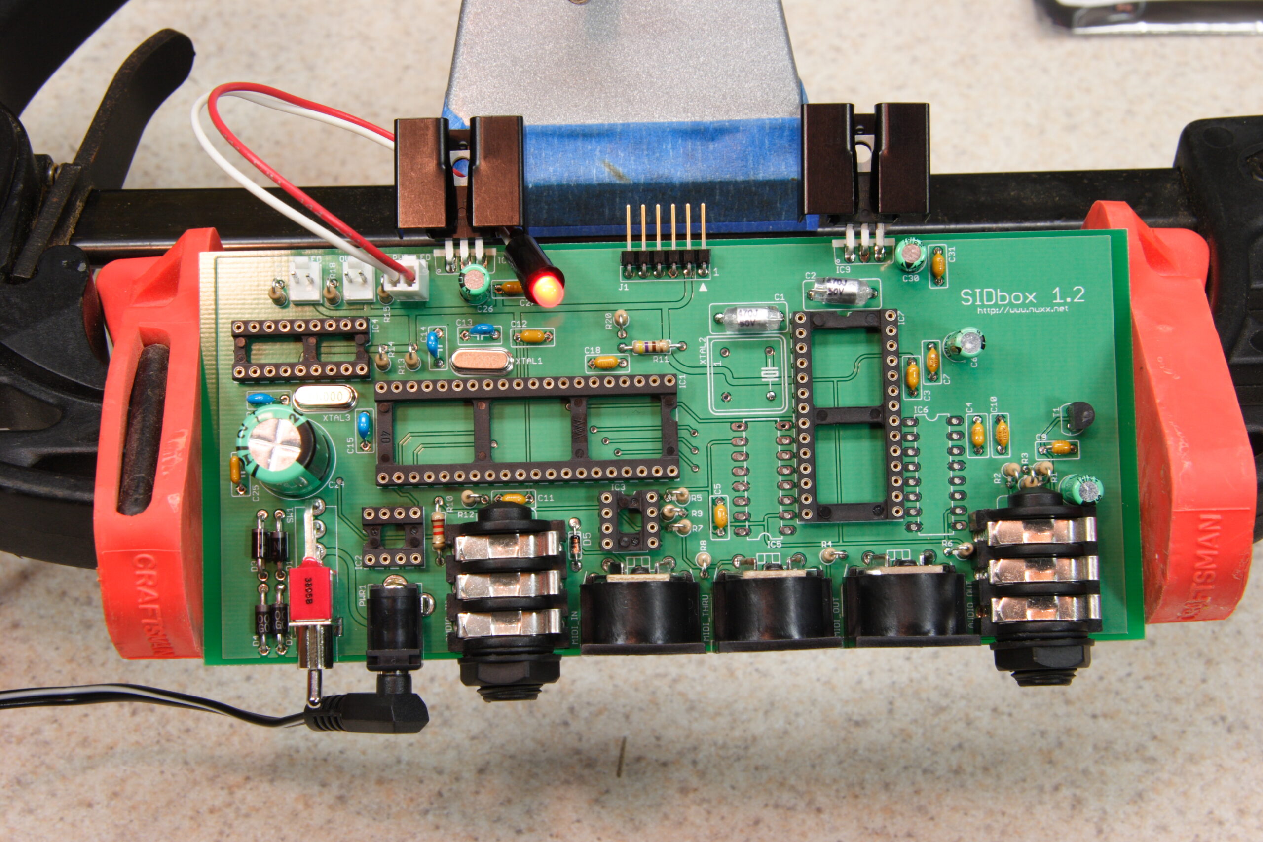
Well, the SIDbox PCBs came in today, and thusly, I assembled one. Well, as much of one as possible… I’m still waiting for some more sockets to arrive tomorrow, and then I need to finish building a PIC programmer. But after that I will hopefully have a working prototype of a single board SID-based sound module.

For background, I’m using what are basically a bunch of different designs from the MIDIbox projects, implemented by me on a single PCB. It will also run the MIOS software which Thorsten Klose has so kindly shared with the world. The main project has a bunch of small ‘modules’ which can be wired together and fitted together in a case to make a synth of one type or another. Well, I wanted a specific type, build portions of a number of the different modules, so I made just that.

I’ve actually been thinking seriously about selling these as kits, and after asking Thorsten (TK) about it in the MIDIbox Forum, I’m seriously thinking about doing it. If I do this, I’ll be merging 5 or 6 of the MIDIbox modules (I can’t remember right now — but it’s a good bit more hardware than seen above) on a single PCB and sticking it in a single case. With my design it’ll be possible (just with the main PCB) to have 8 buttons, an LCD, and all the stuffs I mentioned before. I’m still not sure if I want to do this work, but… I may… We’ll see. :)

Anyway, this post was supposed to be about SIDbox (photo gallery retired) photos, so I’ll link to some specific ones here:

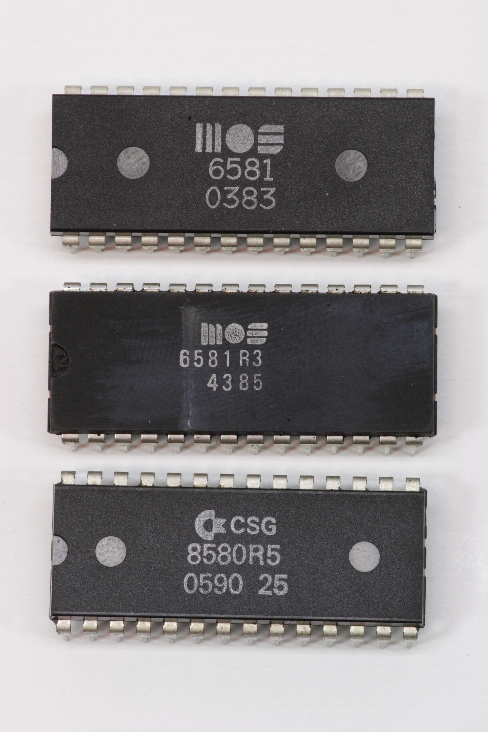
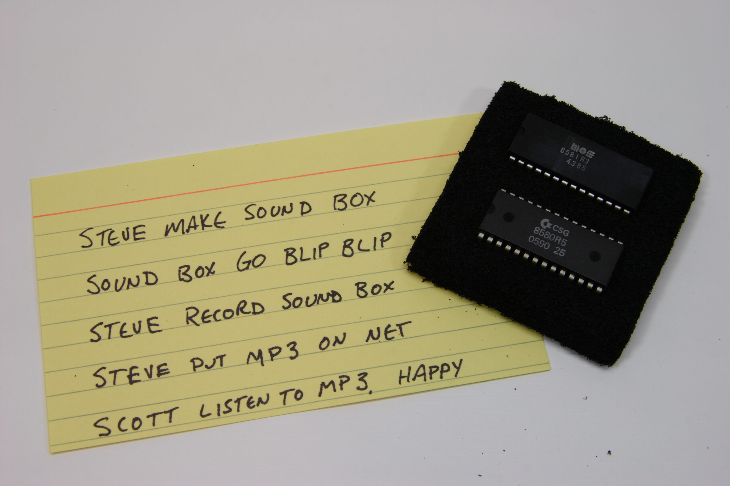
· Mmm. SIDs. A MOS 6581, MOS 6581R3, and CSG 8580R5.
· The nifty note sent by along with some ridiculously generous SIDs.
· 600dpi scans of the finished PCBs. (photo gallery retired)
· Ahh, a nicely laid out array of six SIDbox PCBs.
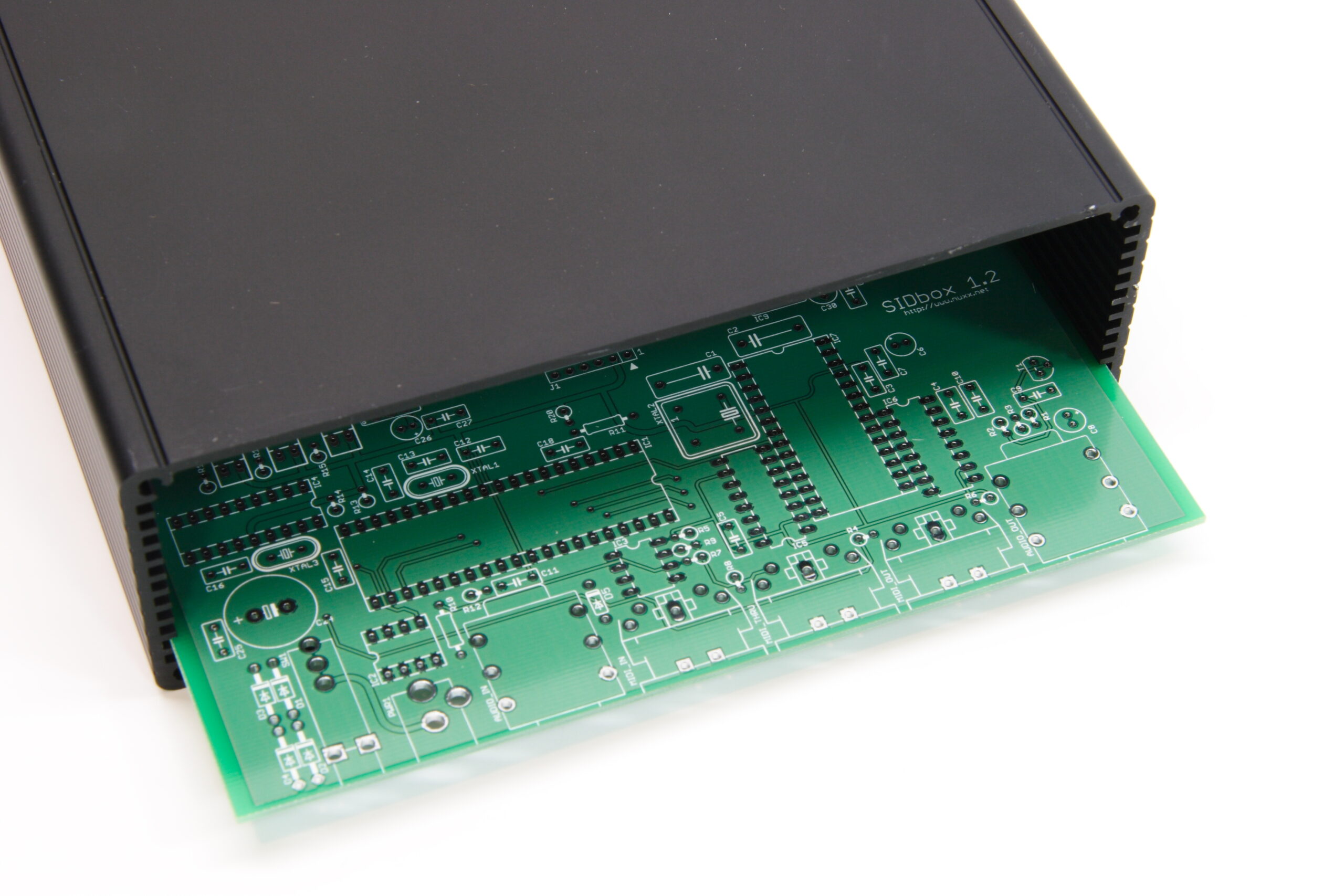
· Ooh, and the SIDbox PCBs even fit in the enclosure. They fit a little too well, but that’s all right.
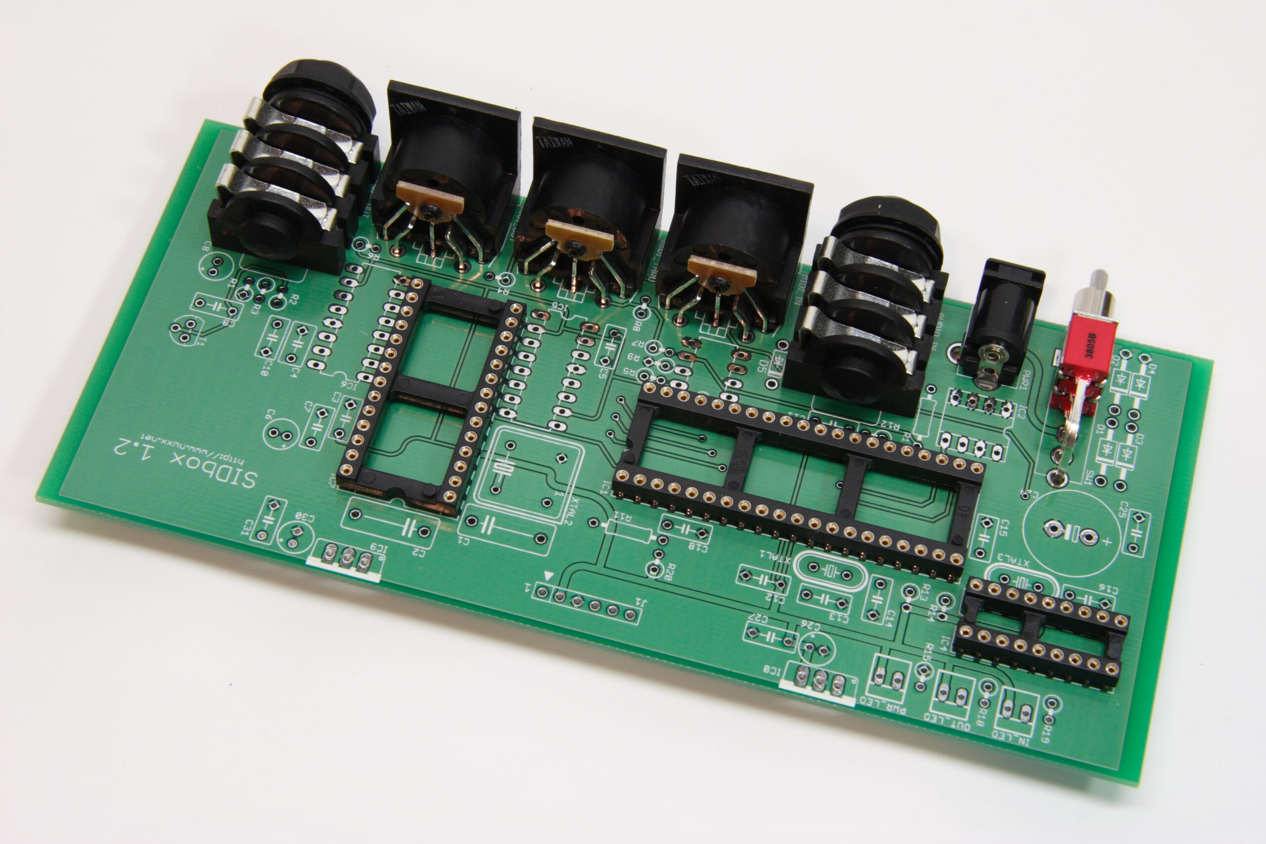
· Test fitting parts to be sure there won’t be any dimensional surprises when actually soldering. Everything looks good from here…
· Well, the power supply works. I was getting a solid 5VDC and 12VDC, which should be ideal for a MOS 6580 SID.
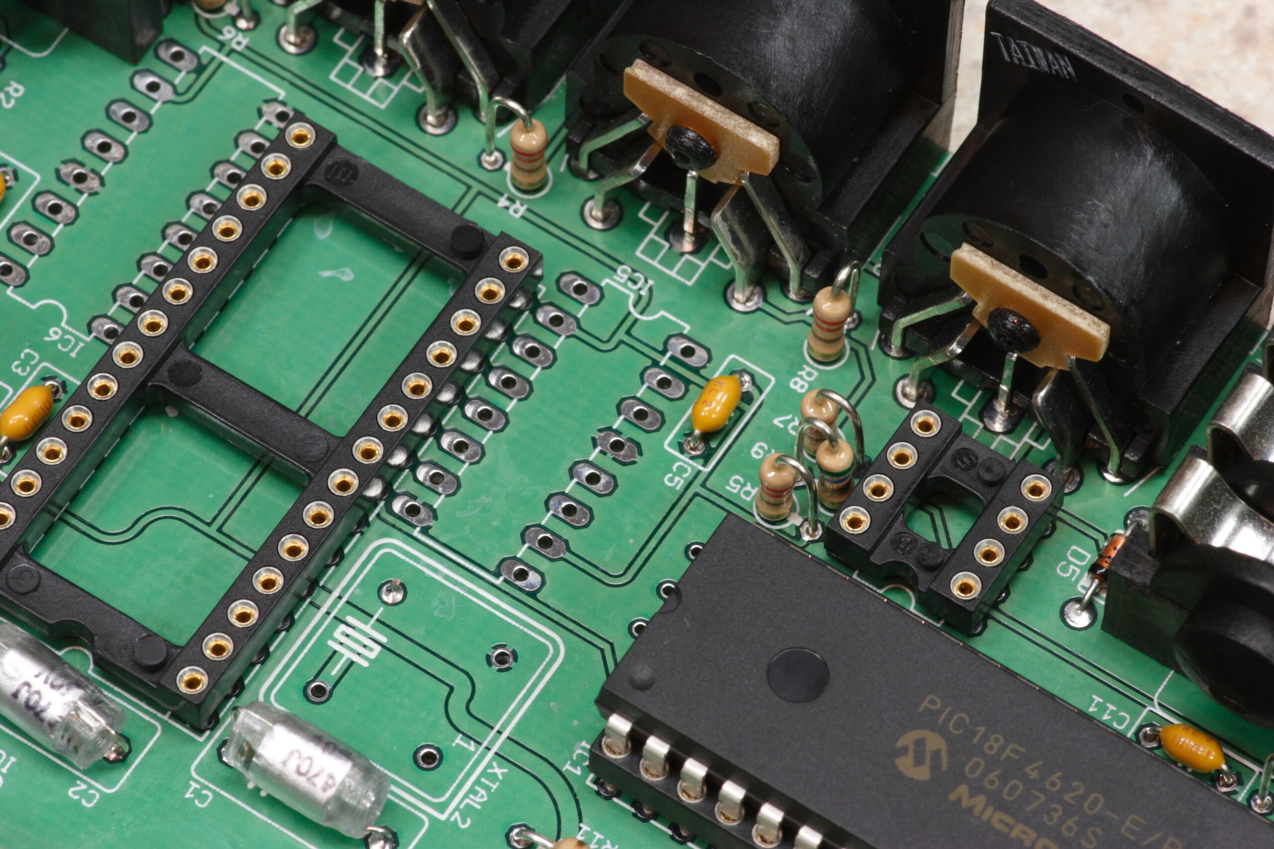
· The PCB with all parts fitted except for two sockets and all ICs.
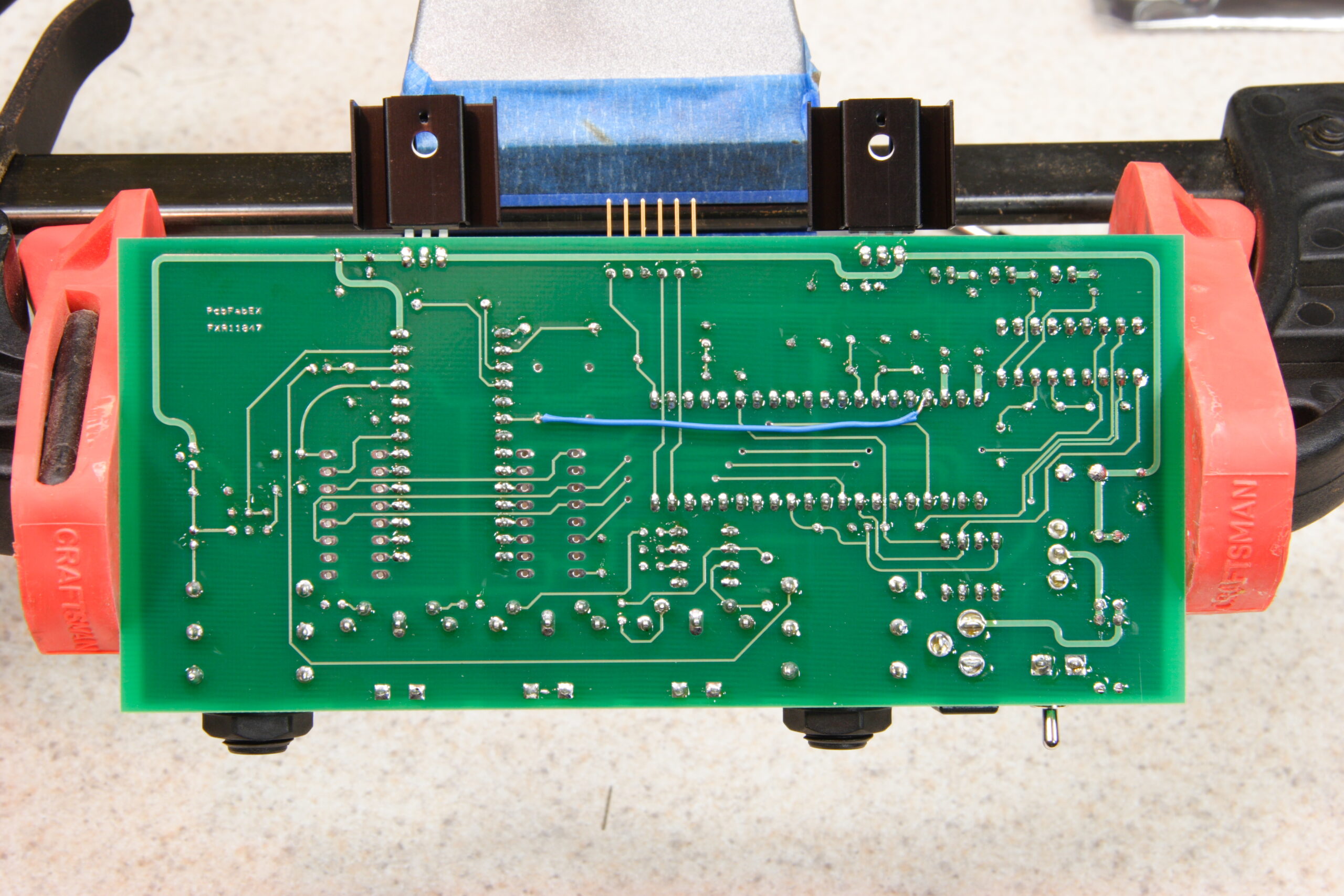
· The bottom side of the SIDbox PCB, where one can see a hardware bugfix. After I ordered the boards I found out about a potential problem, and the blue wire should resolve that.
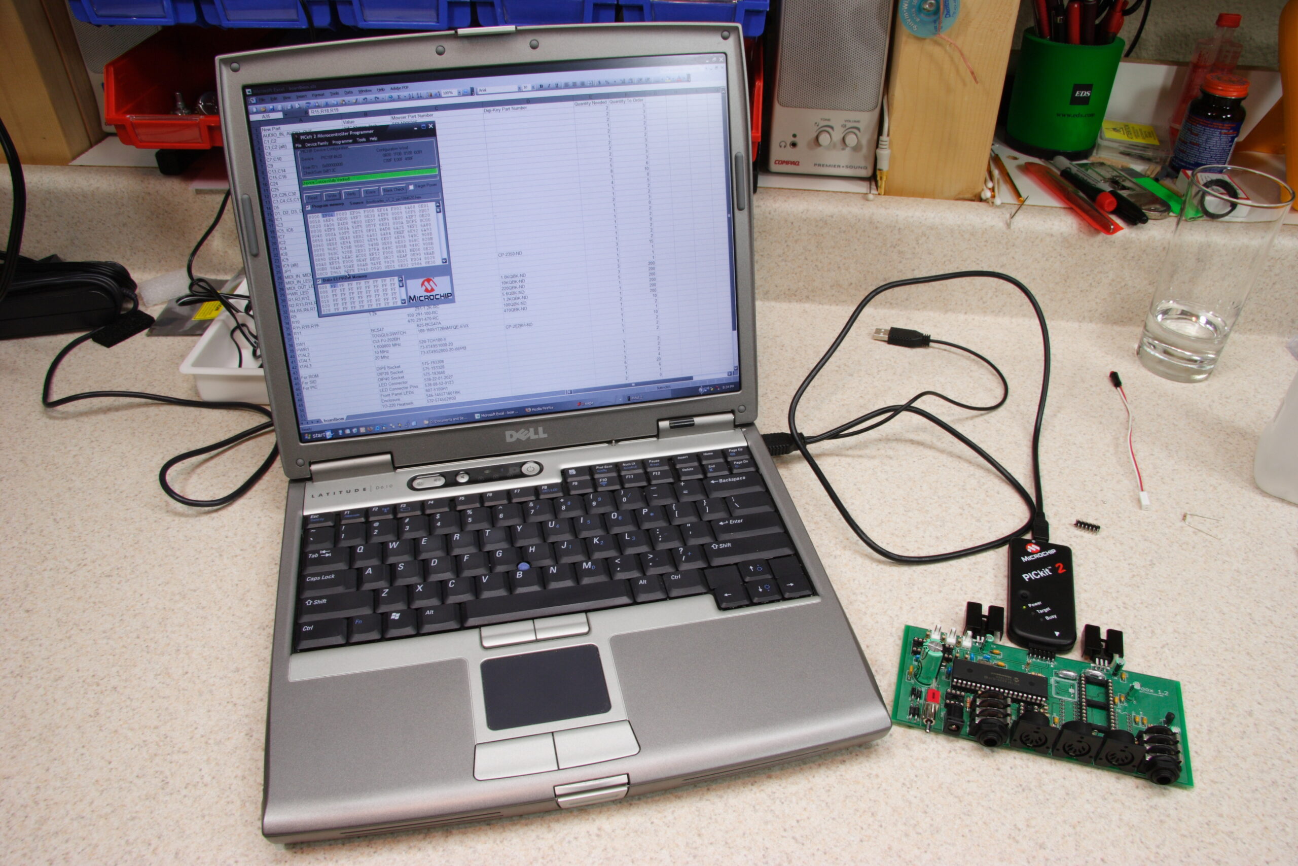
· The SIDbox PCB fitted with a PIC18F4620 to test on-board ICSP. It works.
· A photo which may look familiar to those of you who liked the laser printed board layout plus parts photo from before…

So, yeah. If I’m lucky I will have a working SID-based sound module either tomorrow or Saturday. If not, I’ll probably have a lot to learn… And I’ll be really upset with myself… We’ll see. For now, I’m pretty excited.

electronicsmaking thingsmoved from livejournal

Today I…

Today I…

– Watched a pair of T-38’s take off.
– Watched other aircraft fly about.
– Went to the dirt mall. It’s full of dirty, trashy, awful people.
– Drove through Algonac, East China, and all other routes along M-29 between New Baltimore and Port Huron.
– Poked around beneath the Blue Water Bridge, likely raising the ire of the DHS. I’m sure there were lots of cameras pointing at me.
– Gazed longingly at the land of the more free (aka Canada).
– Visited Kate and Ben in Lapeer.
– Found a local place to buy Yves veggie products: Kroger
– Became frustrated at the PIC programmer I am building, as it doesn’t appear to be behaving properly.

automotiveelectronicsmoved from livejournal

PIC Burner

Tonight I made a parallel port PIC programmer from the MIDIbox PIC Burner schematic. Except I left off the power supply (I’ll use my benchtop one (photo gallery retired)) and added a DIP18 socket for the PIC16F88.

I’m able to switch VPP, VDD, Data, and Clock on and off with the proper voltages coming out of them. Unfortunately the software isn’t recognizing the programmer nor is it able to identify which PIC has been inserted in it. Ah well, I think it’s a matter of parallel port settings, which I’ll mess with another night.

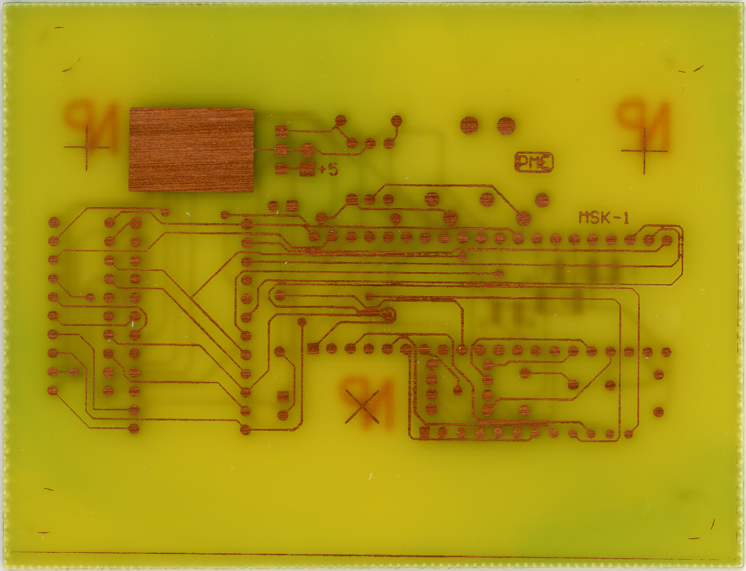
Oh, and I had to etch two PCBs for it, because I screwed up the first one. I also learned what was most wrong with the PCB for the Casio SK-1 MIDI Modification which I screwed up. I think I didn’t let the photoresist ‘develop’ for long enough. I’ve found that with a fairly warm lye solution (the bottle had been soaking in hot tap water for half an hour) it takes about 1:30. With a room temp / cold solution after 12 minutes things still aren’t right. And when a contrast-y image appears, there is still some photoresist left in some points, which makes for an unclean etch.

At least now I know. Now I can go to bed and stuff. Oh, but only after I wash the lead off of my hands.

electronicsmaking thingsmoved from livejournal

SIDbox Update

Well, it looks like I’ve identified a problem with the SIDbox layout. Per this thread I shouldn’t be using a stand-alone oscillator for the SID. Whoops. That means any finally assembled boards will have a jumper running from where the oscillator goes over to pin 18 of the PIC. Not a big deal. Won’t break anything, it’ll just work around a potential problem.

Second, I asked the guy who writes and has designed the core of the MIDIbox stuff if he’d be all right with my selling these boards as kits. He had some suggestions, but he sounds pretty okay with it. I’m just not sure I wish to make the investment. The thread about that can be found here if you are interested.

So, I’m laying the board out again, and I’m going to be getting six prototype boards which should work well, but aren’t usable as kit boards.

I guess the question is whether or not I should attempt to put this together as a kit. I’m thinking an initial (or single?) run of 50 would work well… I just wonder if I can afford it. And I still can’t answer the question of why I want to do it. It just seems like something fun to do.

electronicsmaking thingsmoved from livejournal

SIDbox v1.2 — Boards Ordered


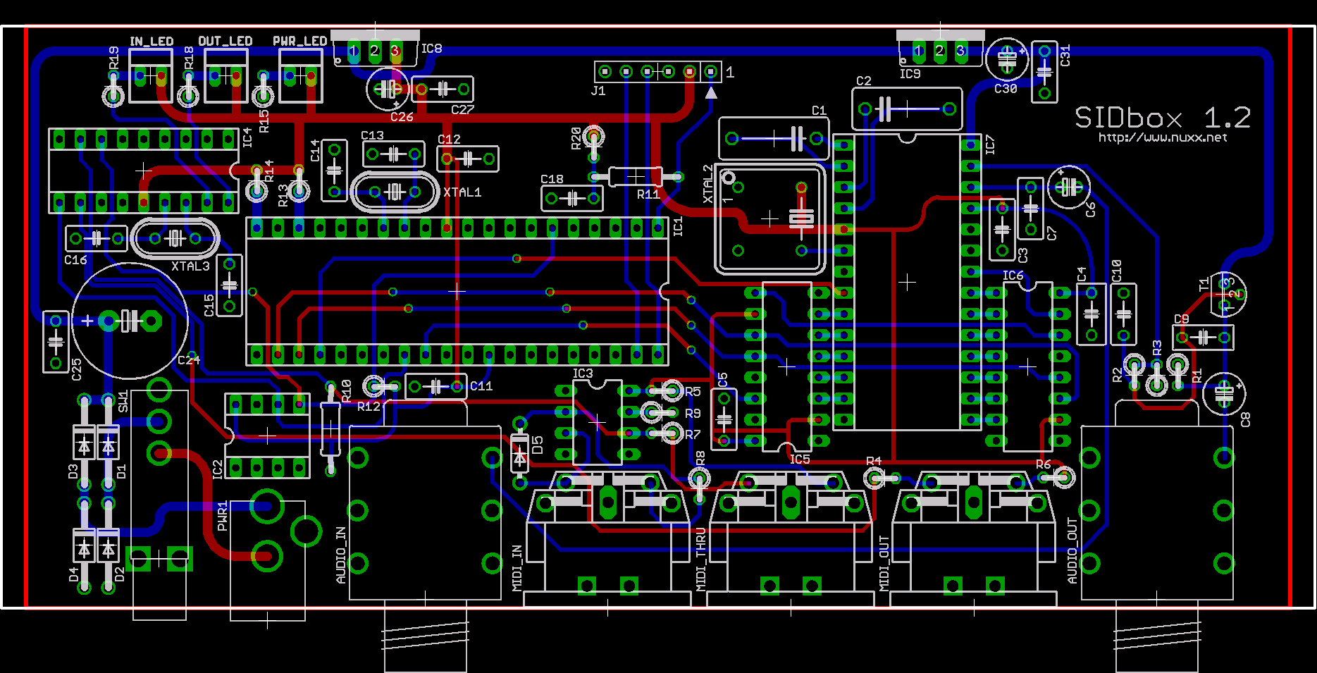
SIDbox PCB Layout v1.2
(Click for SIDbox Gallery…)

Well, I did it. I just submitted an order with PCBFABEXPRESS for six PCBs made to the board layout seen above. US$78 for the boards and $15 shipping, and I should have them some time next week. I also placed an order with Mouser for the ‘new’ PICs (PIC18F4620), the parts for the new MIDI input / output handling (the IIC MIDI Module as opposed to straight off the PIC), and the stuff for a PIC programmer I’m piecing together.

With any luck I’ll have a working SIDbox prototype by the time I head off to the UK. This will be nice. If everything is as I hope, from here on out I’ll just have to etch one more PCB and everything after this will be soldering and assembly. Well… Except for the design of the rear panel for the case, but that won’t happen until I’m certain that I have a functioning board / synth.

Oh, I just remembered that I also need to pick up a USB to MIDI adapter… Hrm. Okay, have to find one of those. Still, things are coming along nicely.

This weekend I headed up to the northern Lower Pennisula (of Michigan) to visit my grandparents and meet up with for dinner. I also went to Sleeping Bear Dunes National Lakeshore (and received a mighty sunburn) and Hartwick Pines State Park. Photos from each are forthcoming.

I guess tonight I’ll just go and try to acquire some PCB etchant from Radio Shack. Then I’ll confirm / finalize this PCB design for the PIC programmer, etch it, and… That’ll probably be the whole evening.

electronicsmaking thingsmoved from livejournaltravel

PICs, SIDbox, and Mistakes


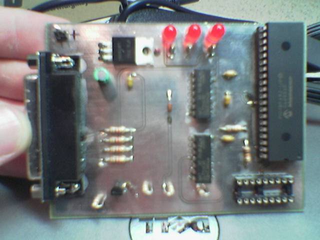
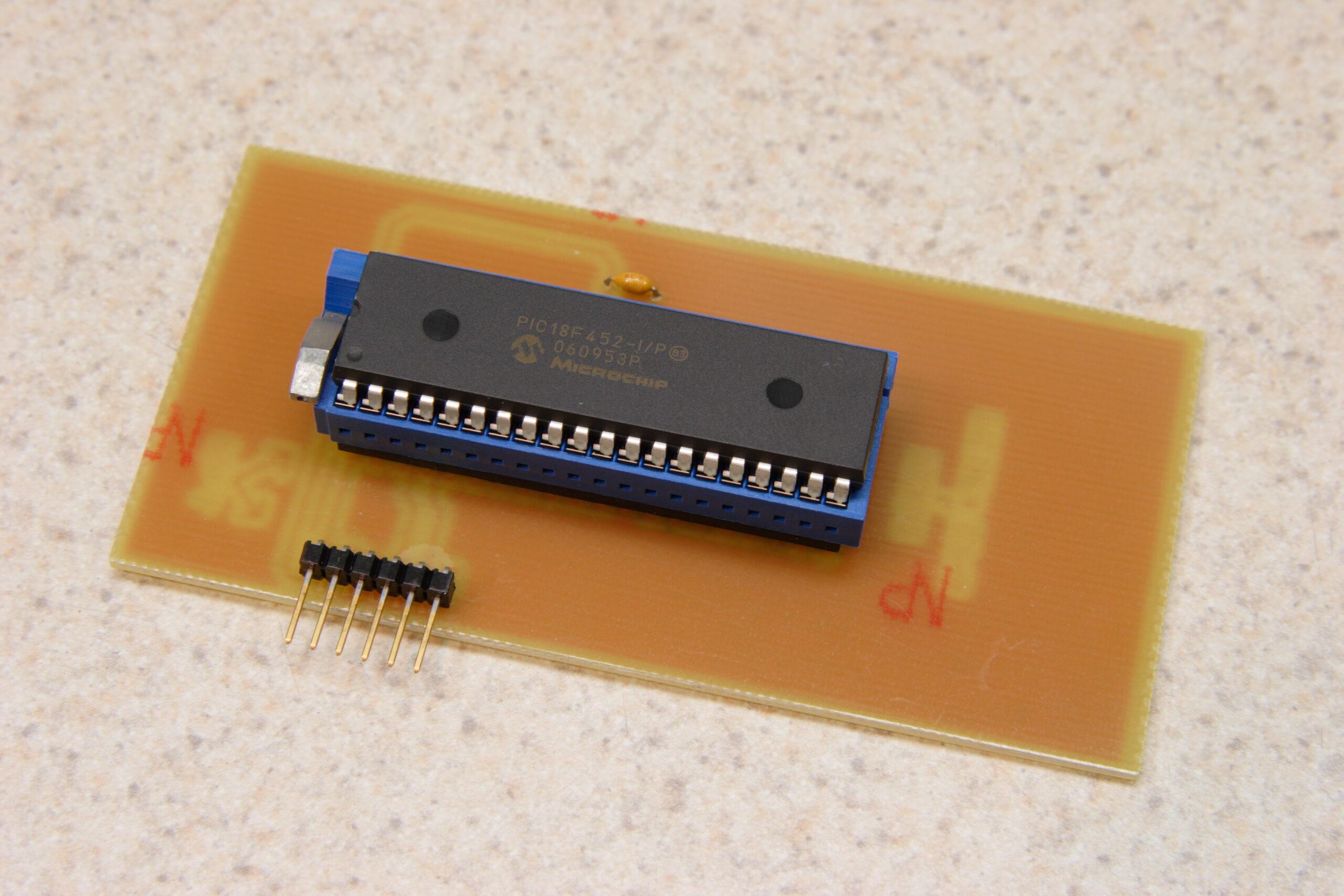
Microchip PICkit2 to DIP40 Adapter

Okay, so this post is going to contain lots of babbeling as I try to get my thoughts together…

First off, it seems that I made a bit of a mistake with this SIDbox I’m working on. The mistake stems from my thinking that the PIC18F452 is part of the PIC18F4520 and can thereby be programmed with the PICkit2 which I have. I was wrong.

Based on this faulty thinking, I both built the PICkit2 to DIP40 adapter (photo gallery retired) which you can see above and included support for using this programmer in the SIDbox (photo gallery retired) I hope to build.

So now I’ve got some hardware / connectors on the SIDbox PCB which are pretty much useless as the device would normally work.

At this point I have two choices…

The first is to build a new PIC programmer (probably connected to a serial port) which will properly flash the PIC18F452 using the 1×6 pin header found on the DIP40 adapter (photo gallery retired) and the SIDbox (photo gallery retired) and use the existing hardware layout and order the PCBs.

The second option is to use a newer PIC, the PIC18F4620, on the SIDbox instead. This has the advantage of being completely compatible with my programmer and thusly the adapter and the programming hardware on the SIDbox board. However, there appears to be a bug in the hardware of the PIC18F4620. The end result of this bug is that one can’t use a MIDI output directly from the chip. So, I’ll have to add some additional hardware to provide MIDI output. On the upside, this extra hardware (the MIDIbox IIC MIDI module) provides for MIDI LEDs, making part of my existing design redundant. That means some board space is freed up for the new hardware.

So, at this point I’m not completely certain what to do, but based on the responses I am getting to this post at the MIDIbox forums, I think the second option is going to be the best one. In fact, I’m going to change the schematic and start laying out the board for this now. Just in case I decide that’s the best way to go.
electronicsmaking thingsmoved from livejournal

SIDbox Update… Again…


SIDbox PCB Layout
(Click for more of the SIDbox album…)

Nope, there’s not much in the SIDbox (photo gallery retired) album yet, but I do have what I believe to be the final schematics and PCB layouts. I’m just waiting on some parts from Mouser and Digi-Key to arrive so I can confirm the desired layout, then I’ll place the order for everything.

Also, here is a post I made to the MIDIBOX.ORG Forum about the project:
Cut to save page space…

electronicsmaking thingsmoved from livejournal

SIDbox Update

Well… I just ordered about $150 worth of components for the SIDbox project. This is everything needed to build the first prototype except etched end panels, the PCBs, and the power supply. I’m waiting to order the PCBs until I can confirm the switches work as expect. The power supply is somewhat dependent on the type of SID installed in it. And the etched end panels… Well… They are just a finishing item, so those will wait until I’m certain that this thing actually works.

Also, I’m nailing down some final things on the PCB layout. Just… Tweaks and stuff.

electronicsmaking thingsmoved from livejournal