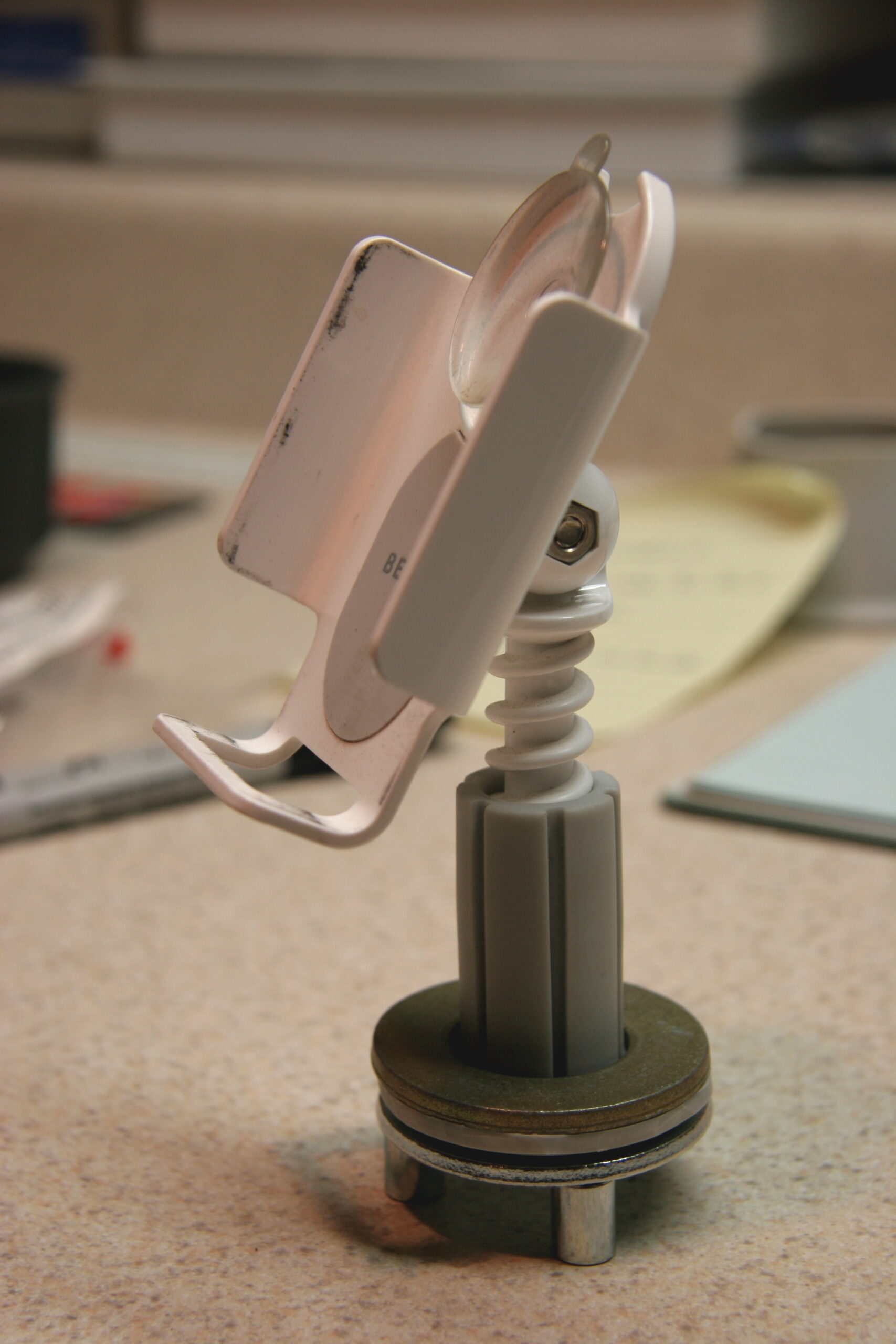
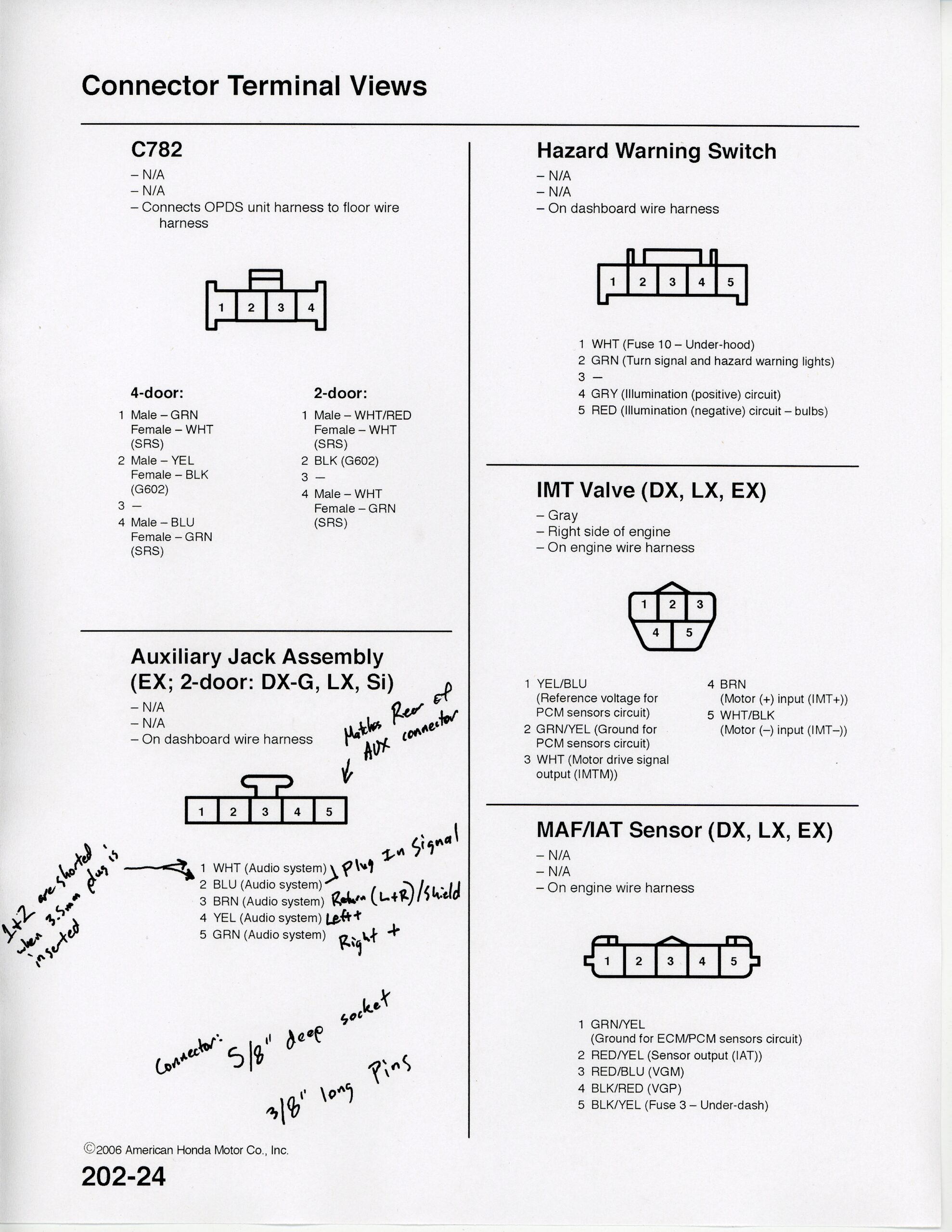
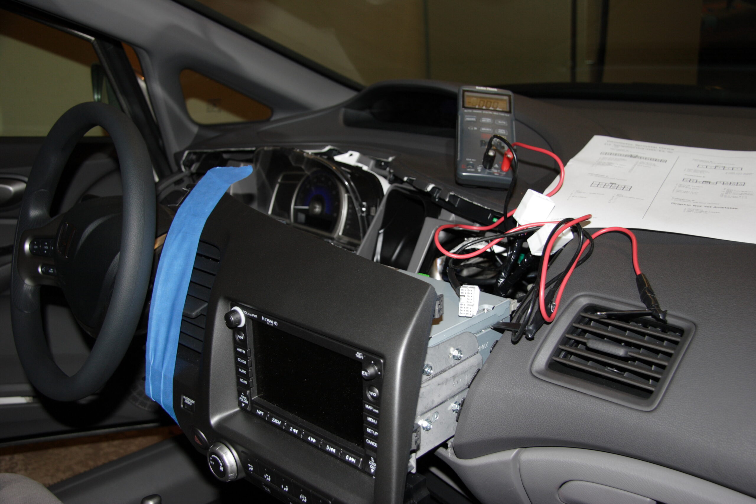
Honda ‘Auxiliary Jack Assembly’ Connector
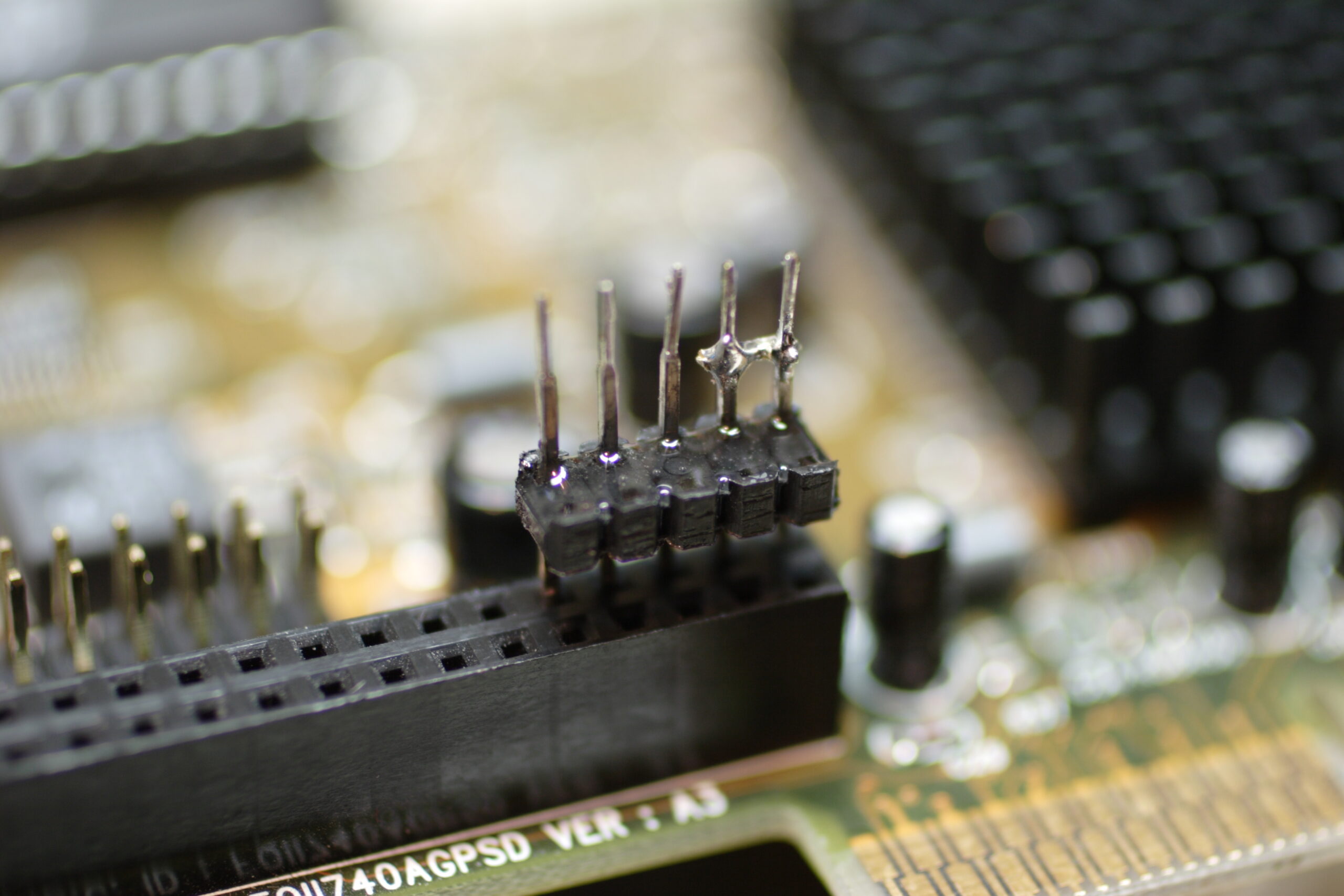
Connector for ‘Auxiliary Jack Assembly’ on Honda Wiring Harness
(Click for more…)
Ahh, I think I finally figured out exactly how I would make the connector for inside the dashboard of my car for inputting audio into the connector which originally plugged into the rear of the Aux In connector on my dashboard.
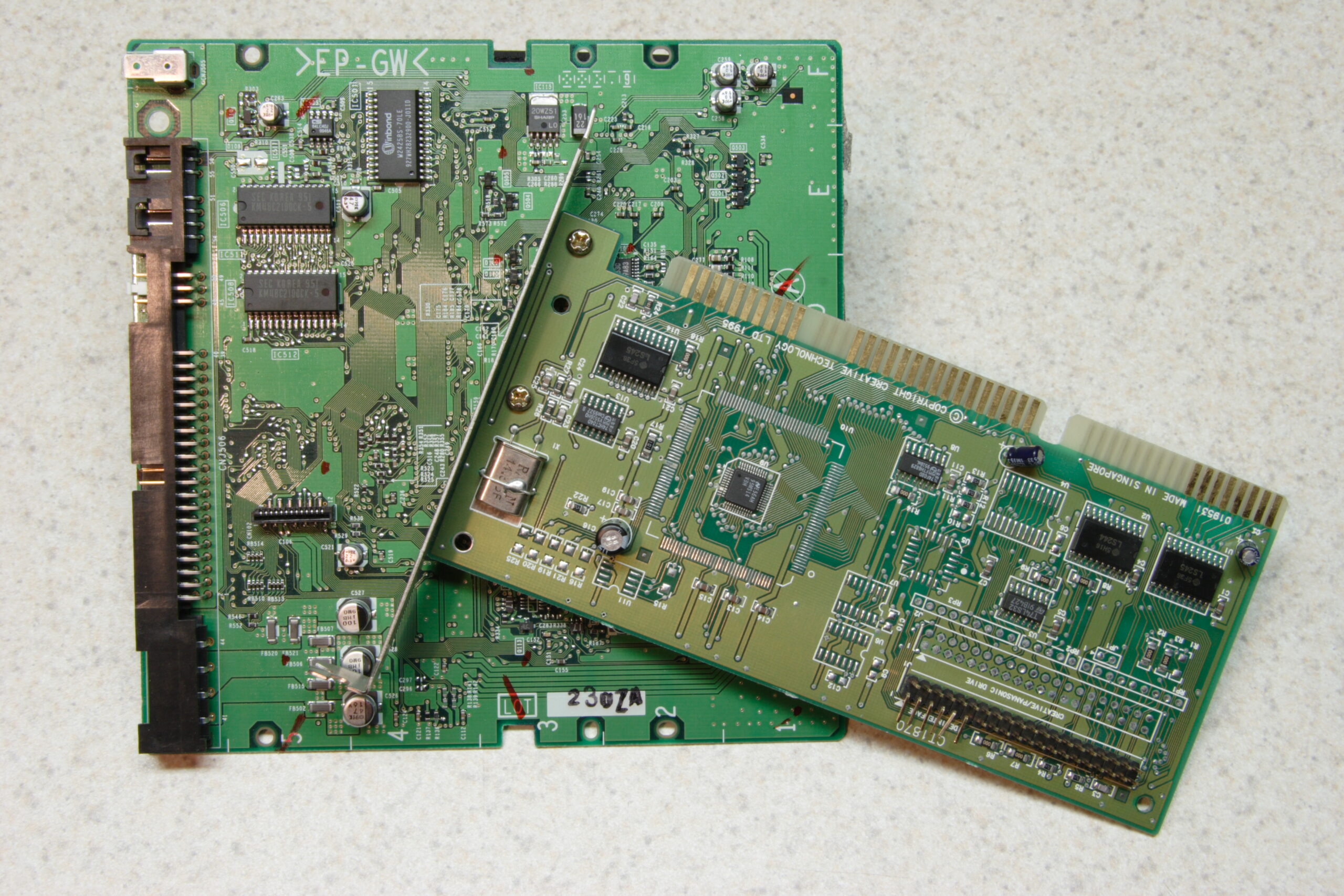
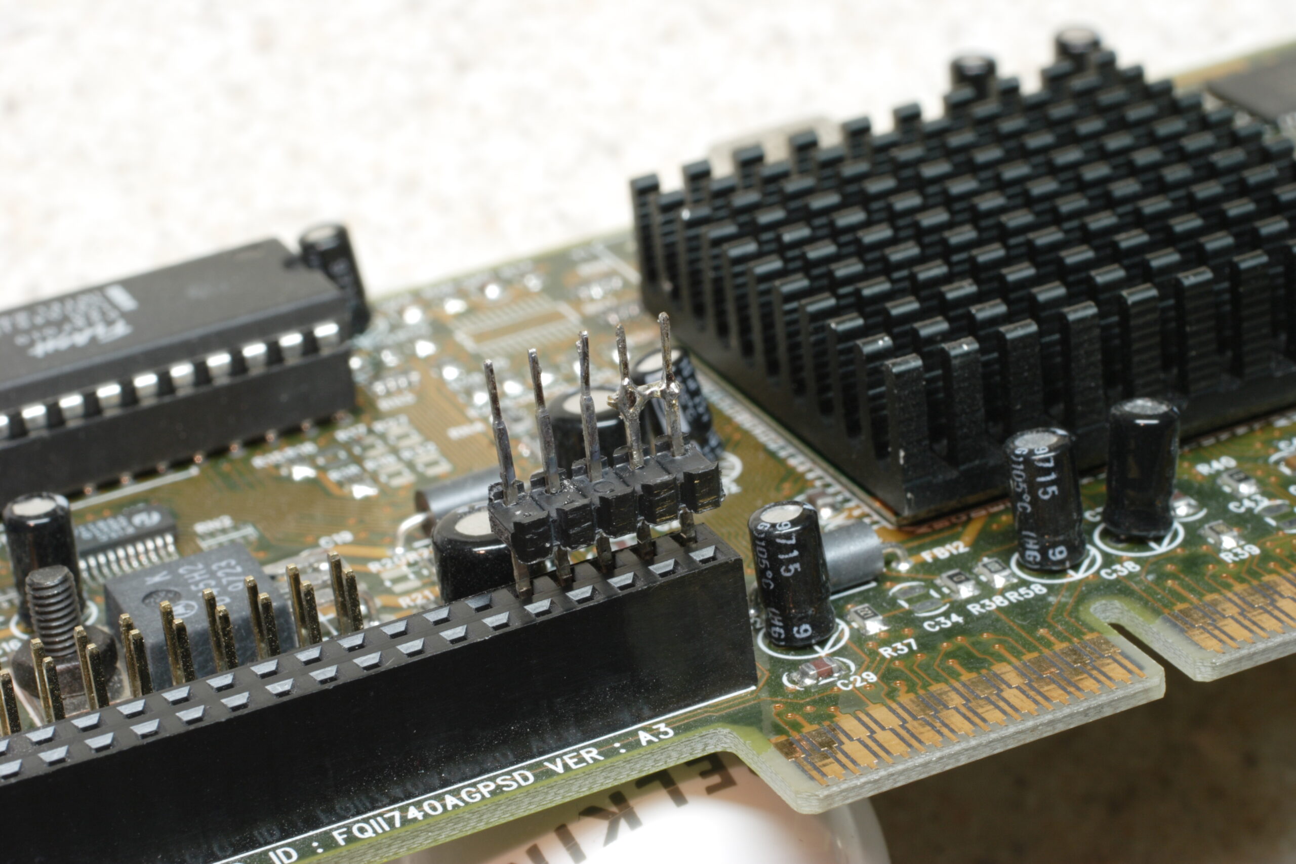
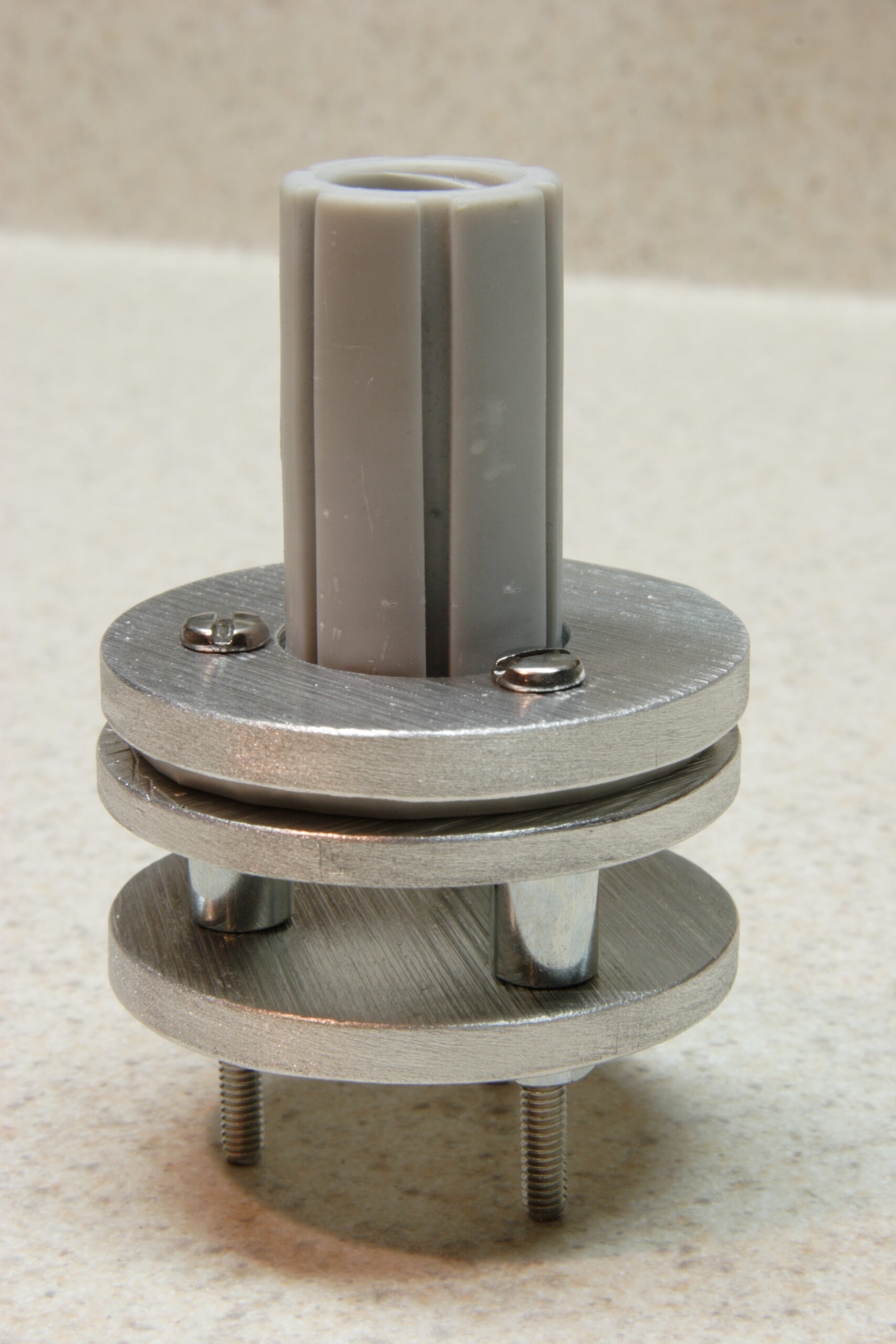
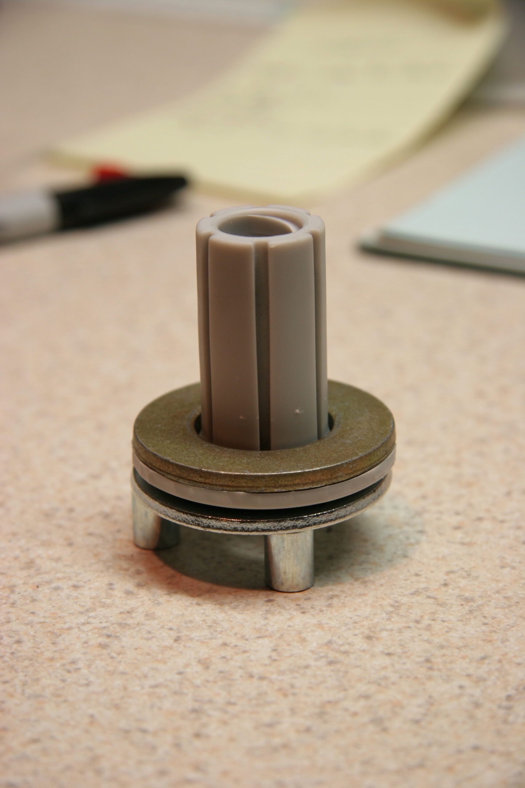
What I ended up doing was taking a PCB salvaged from a 2x CD-R and an old CD-ROM drive controller and pulling the long pins off of the CD-R’s PCB and the plastic .100″ spacer from the CD-ROM controller. I then straightened the pins and assembled the pins into the connector, first bridging pins 1 and 2. (This indicated to the head unit on Honda cars that there is something connected to the auxiliary input.)
I then fit everything into a random (probably the VESA connector) header on an old video card and ensured that there is 3/8″ of pin hanging out the non-wiring side of the spacer. After getting everything aligned, I applied a bit of epoxy to the back (wire) side of the spacer to hold the pins in place.
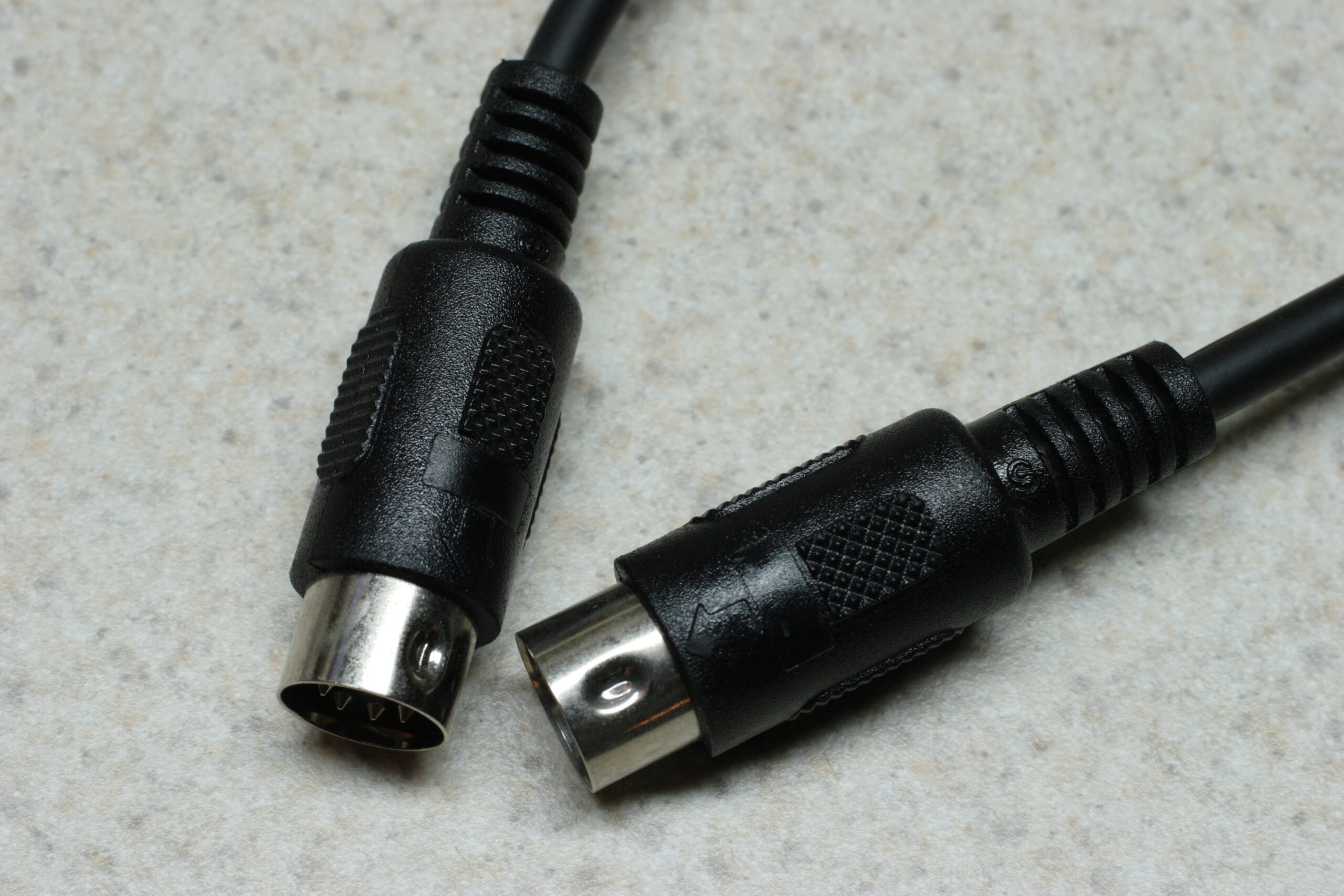
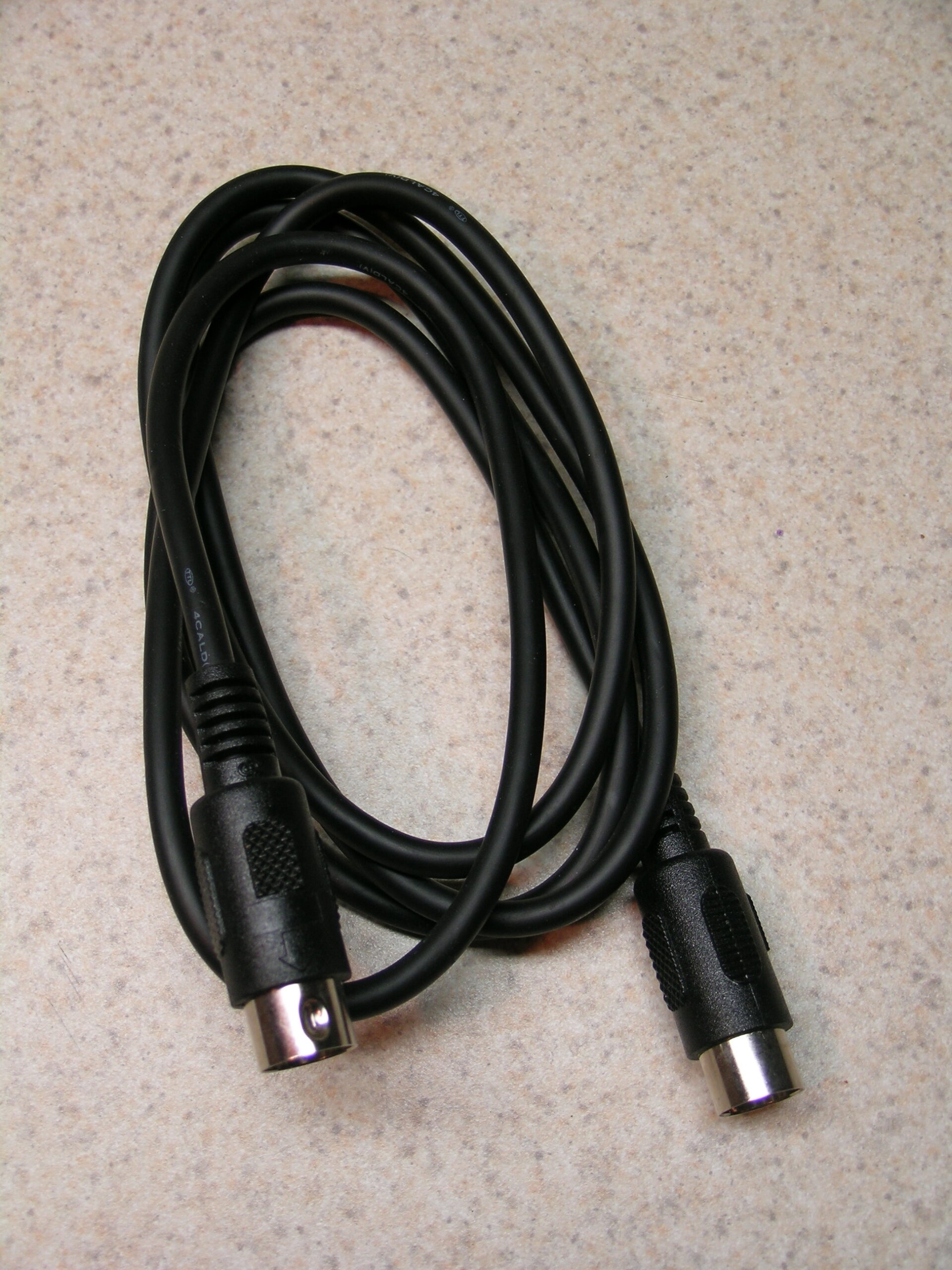
So, tomorrow, likely after the epoxy has cured, I’m going to cannibalize another MIDI cable for it’s nicely made wire assembly, and I’ll use the red / white / green wires and connect them to the left / right / return (ground) pins on the newly made connector. Then I’m going to attempt to pot the entire solder/wire portion of assembly in epoxy. This will provide a nice bunch of strain relief along with ensuring that nothing in this connector shorts out.
Even though I only need three pins, I think I’ll use a DB9 connector for the other end, the one which will connect to the junction box. It’ll be shielded, easy to solder, unlikely to fall out (screws on the connector), and quite solid.
So, yeah… It’s shaping up nicely thus far. Now it’s bed time or something.