9090 Update
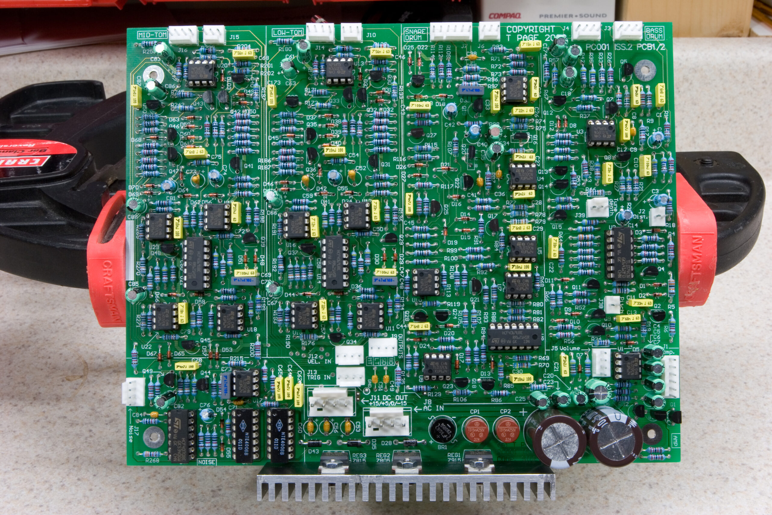
9090 PC001 Component Side — All Parts Fitted
(Click for solder side…)
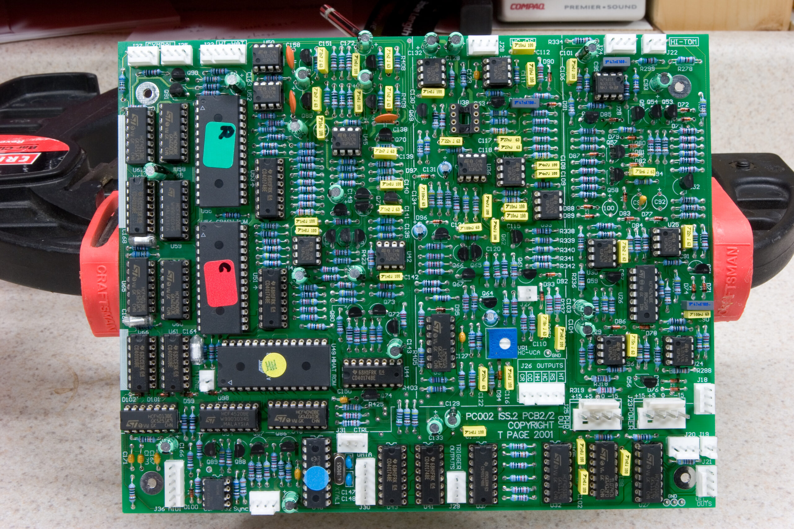
9090 PC002 Component Side — All Parts Fitted except U38, C92, and C100
(Click for solder side…)
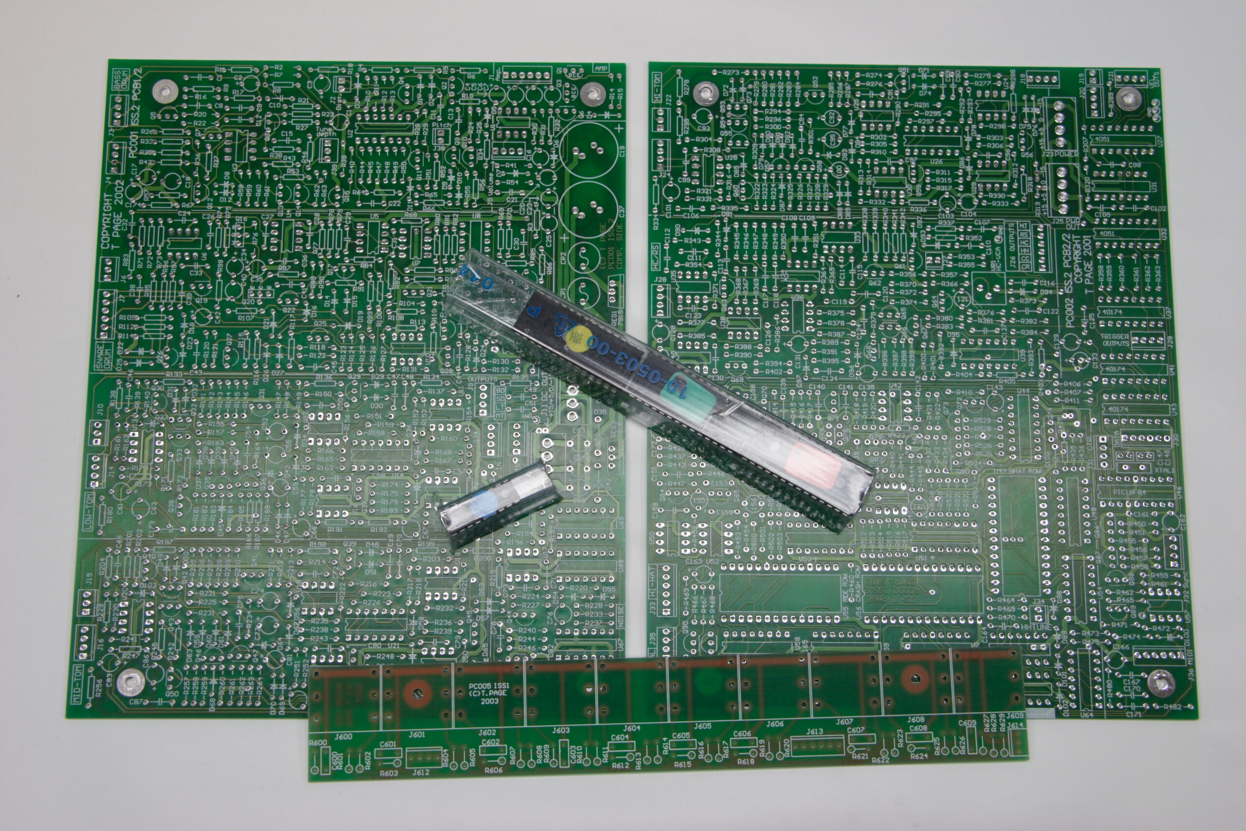
Wow, I can’t believe it’s come this far. Starting a few months ago with a pile of PCBs and a couple of ROMs and a microcontroller I got to work building Trevor Page’s 9090, a clone of the sound creating bits inside the Roland TR-909.
I’ve been working on it here and there, ordering all the resistors one day, a bunch of caps another, etc. Except for my screwing up and failing to acquire (in the course of three separate rounds of ordering) enough .47uF electrolytic capacitors and an IC (CA3080) which I’m waiting to receive in the mail, the PCBs are complete.
In addition to the two above, there is also a board with ten separate 1/4″ mono jacks which handles audio output for each of the ten separate instruments. The component side of that board can be seen here and the solder side here.
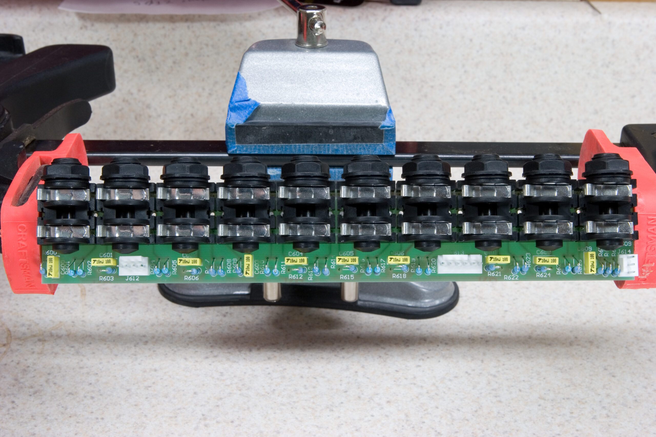
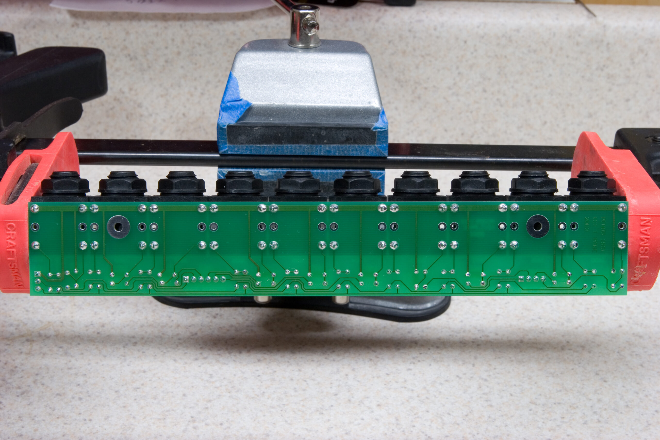
So, what’s left before it is done? Quite a bit, unfortunately. Let’s see…
· Get the missing three parts and fit them in place.
· Decide on an enclosure and design the front and rear panels so they fit the pots, knobs, LEDs, power switch, audio jacks, MIDI jacks, and mains connector.
· Order remaining parts.
· Design indicators / artwork and figure out the best way to apply / fit them.
· Cut the enclosure to fit all the externally-fitted components (pots, jacks, etc).
· Physically assemble the enclosure and mount the boards inside.
· Cable everything together.
· Test everything to be sure all instruments and switching jacks work as expected.
· Troubleshoot, if needed.
As you can see, there is quite a bit more to go, although I think this is a good stopping point for now.
Too bad I don’t live closer – I’d bring my TR-909 over for a comparison.
Wow, I’d really like to get my hands on one of those :)