SIDbox… Goes Somewhere…
Well, power works.
(Click for more SIDbox photos…)
Well, the SIDbox PCBs came in today, and thusly, I assembled one. Well, as much of one as possible… I’m still waiting for some more sockets to arrive tomorrow, and then I need to finish building a PIC programmer. But after that I will hopefully have a working prototype of a single board SID-based sound module.
For background, I’m using what are basically a bunch of different designs from the MIDIbox projects, implemented by me on a single PCB. It will also run the MIOS software which Thorsten Klose has so kindly shared with the world. The main project has a bunch of small ‘modules’ which can be wired together and fitted together in a case to make a synth of one type or another. Well, I wanted a specific type, build portions of a number of the different modules, so I made just that.
I’ve actually been thinking seriously about selling these as kits, and after asking Thorsten (TK) about it in the MIDIbox Forum, I’m seriously thinking about doing it. If I do this, I’ll be merging 5 or 6 of the MIDIbox modules (I can’t remember right now — but it’s a good bit more hardware than seen above) on a single PCB and sticking it in a single case. With my design it’ll be possible (just with the main PCB) to have 8 buttons, an LCD, and all the stuffs I mentioned before. I’m still not sure if I want to do this work, but… I may… We’ll see. :)
Anyway, this post was supposed to be about SIDbox (photo gallery retired) photos, so I’ll link to some specific ones here:
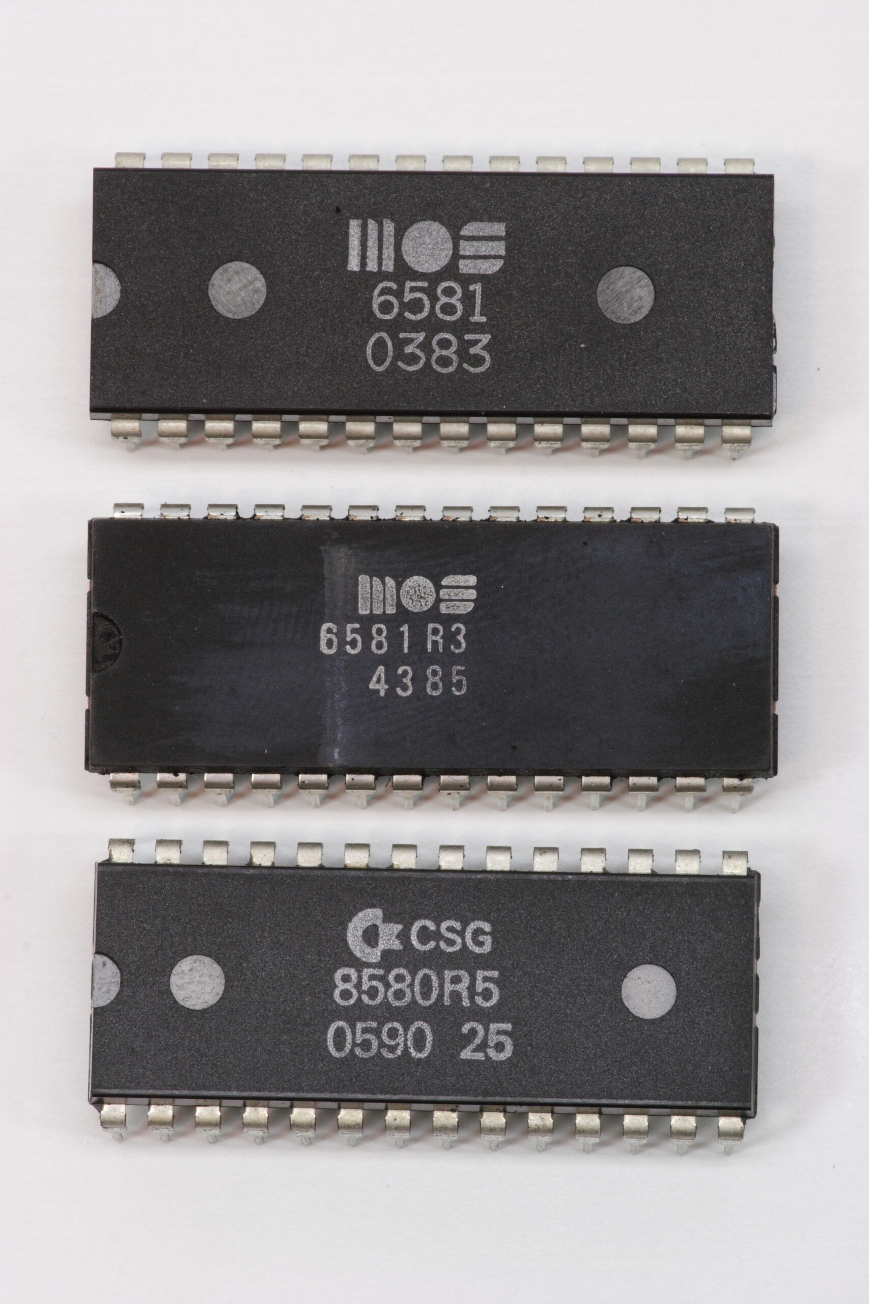
· Mmm. SIDs. A MOS 6581, MOS 6581R3, and CSG 8580R5.
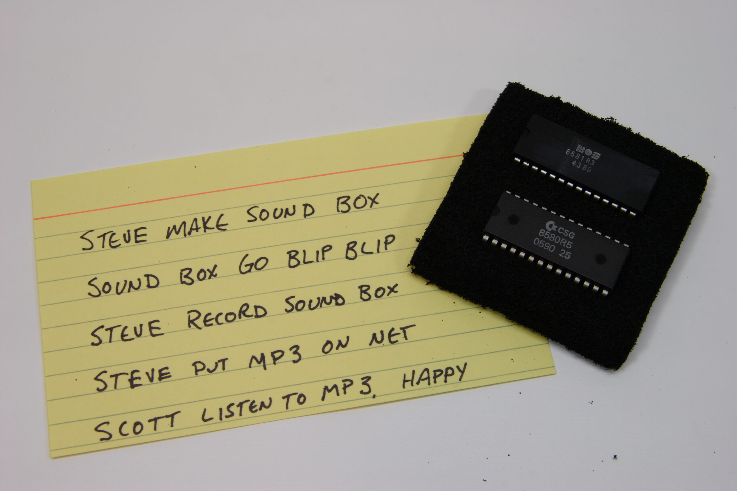
· The nifty note sent byalong with some ridiculously generous SIDs.
· 600dpi scans of the finished PCBs. (photo gallery retired)
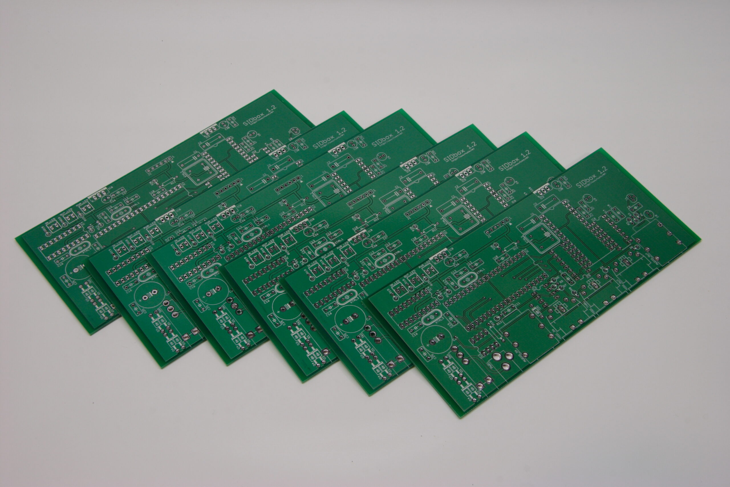
· Ahh, a nicely laid out array of six SIDbox PCBs.
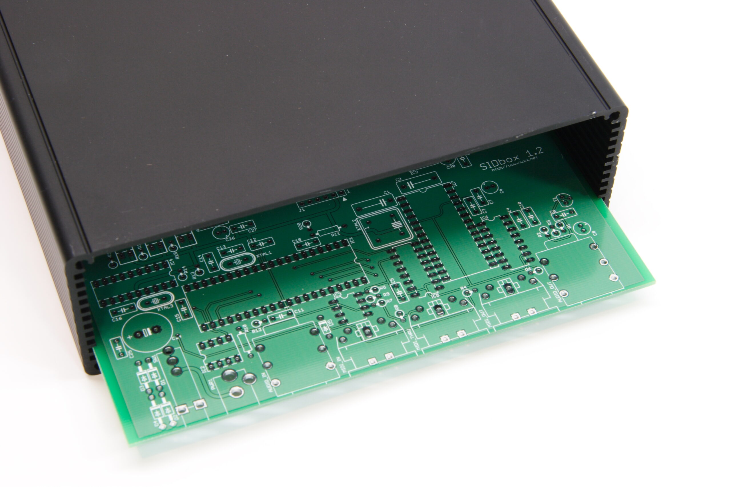
· Ooh, and the SIDbox PCBs even fit in the enclosure. They fit a little too well, but that’s all right.
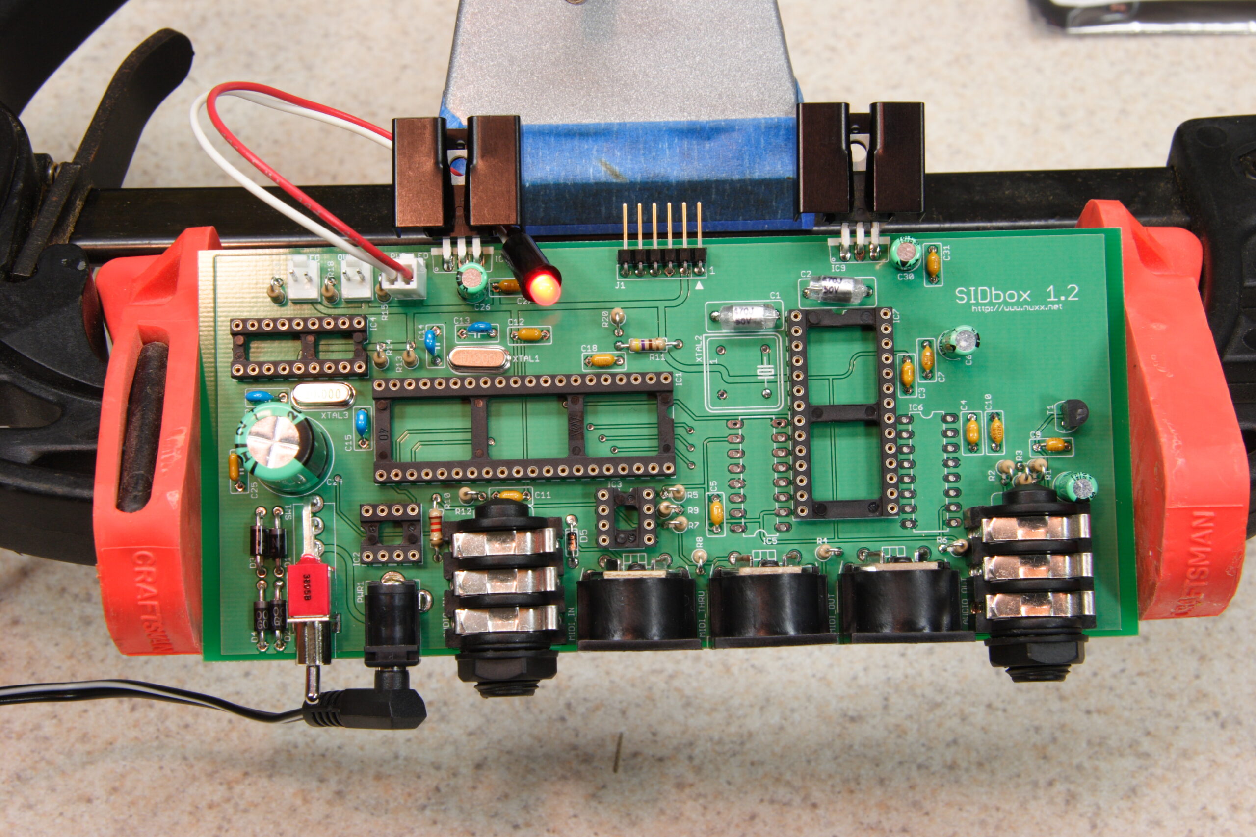
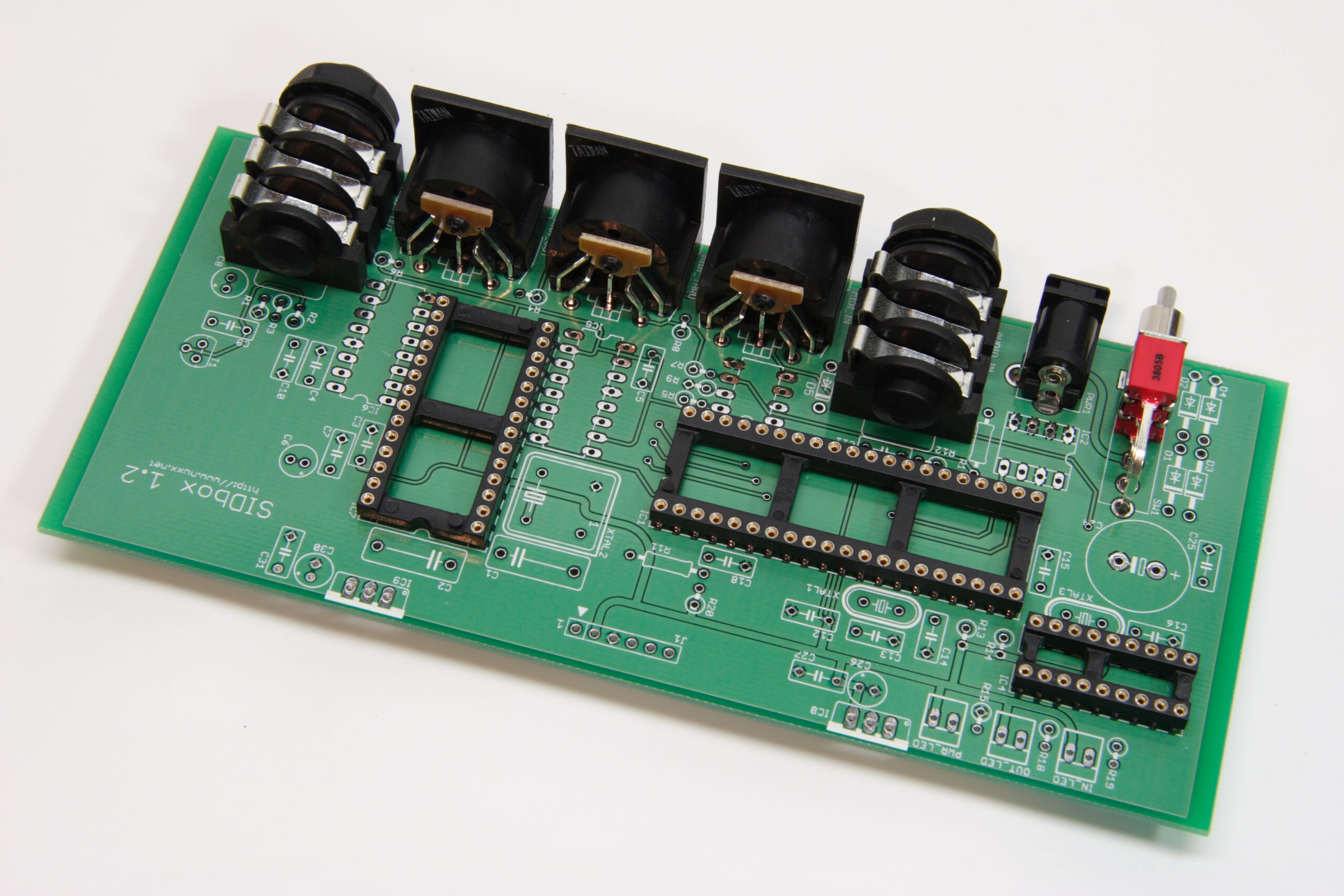
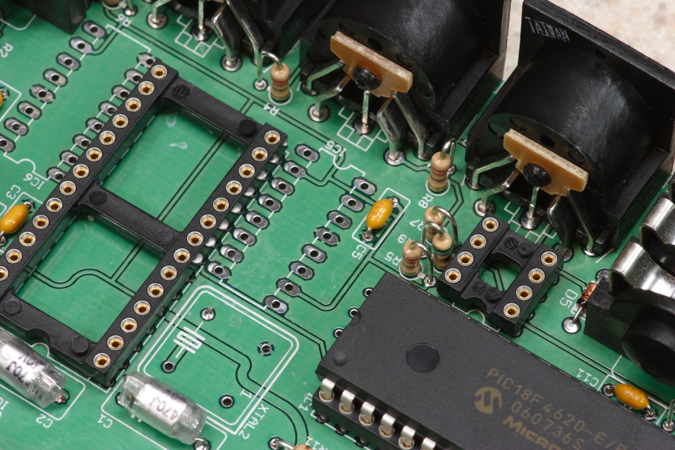
· Test fitting parts to be sure there won’t be any dimensional surprises when actually soldering. Everything looks good from here…
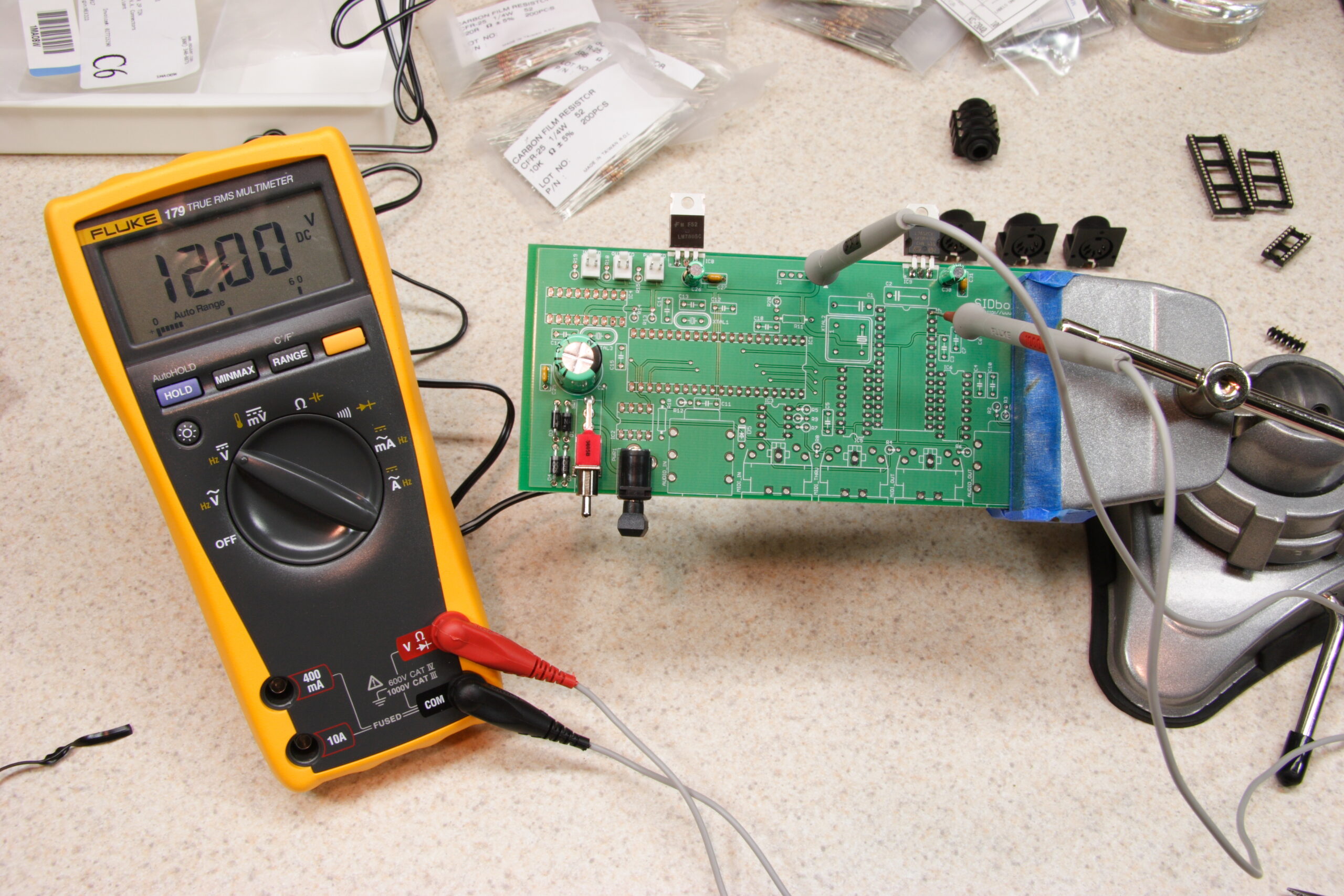
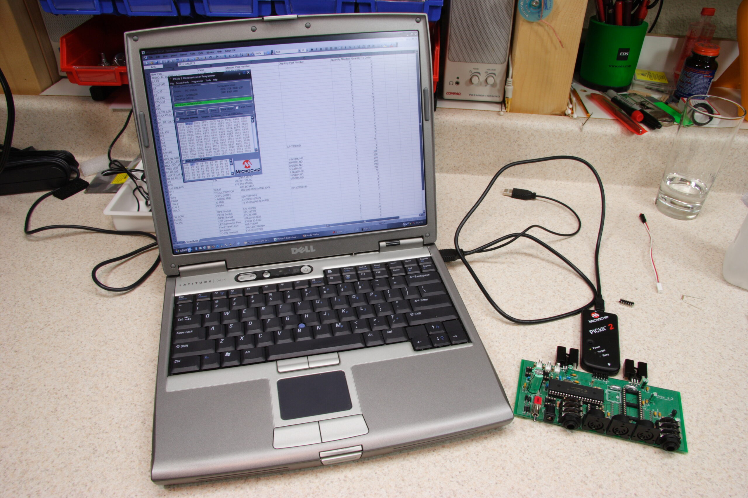
· Well, the power supply works. I was getting a solid 5VDC and 12VDC, which should be ideal for a MOS 6580 SID.
· The PCB with all parts fitted except for two sockets and all ICs.
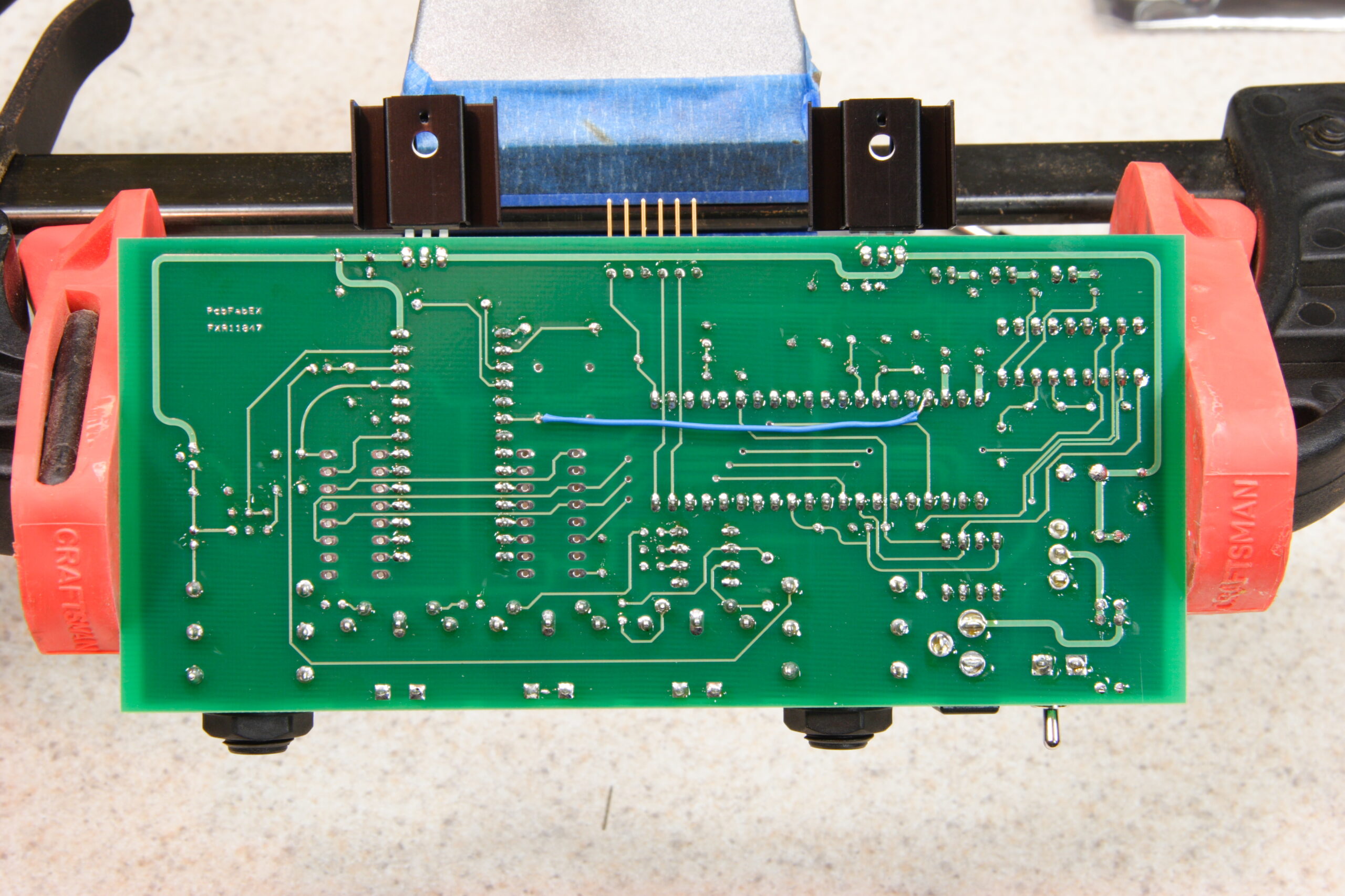
· The bottom side of the SIDbox PCB, where one can see a hardware bugfix. After I ordered the boards I found out about a potential problem, and the blue wire should resolve that.
· The SIDbox PCB fitted with a PIC18F4620 to test on-board ICSP. It works.
· A photo which may look familiar to those of you who liked the laser printed board layout plus parts photo from before…
So, yeah. If I’m lucky I will have a working SID-based sound module either tomorrow or Saturday. If not, I’ll probably have a lot to learn… And I’ll be really upset with myself… We’ll see. For now, I’m pretty excited.
Oh, I didn’t realize you were supporting a basic UI on your board… I’m a little more interested then. Will it let you still attach more ain/din/dout boards for a full UI, or will it be limited to the button/LCD/single encoder one?
I wasn’t originally, but the plan for the kits — if I do them — is to have the chip for a 8 buttons on the board, and a header so one can add other DIN modules. The DIN/DOUT headers (the J6-J9) ones will be there. I’ll also be adding the stuff for an LCD, so it can be just plugged into the board. Also, there will be a header there to add more ROM (Banksticks) if one desires. It’ll also use the newer PIC, which is needed for the MIDIbox SID 2.0 (or whatever) stuffs. Oh, I’m replacing the J9 name with J9A because it’ll really be the other side of a the latch to which the buttons. This will all be documented.
After reading TK’s aforementioned reply, I realized that I would ideally have a MIDIbox SID in a small box, with a small LCD and a next/previous button. One could program patches via a computer, then either use bank select messages or the next/previous buttons to pick which patch they want to have the box play. That’d be just be a lot better.
So, as a bit of an exercise, I’m working on laying out a single PCB that can do all of this, and also be expandable. I’m not sure if I’ll have them made yet, but we’ll see… A lot of this depends on how the SIDbox turns out. If it works, I’ll likely go further. If not — and if I can’t figure out what I did wrong — I’ll probably stop at this point.
My hope right now is that the kits will cost around US$50 – $70 for everything which is fixed on the board and a power supply, except for a SID. The case itself which I’m fitting the board for is $25 – $27 through Mouser, and custom-milled front and rear panels will add quite a bit more. Also, I think some people may want to just put the board in another case, so… Yeah. I’ve also added 4mm holes in the corners of the board to facilitate mounting for those people.
Yeah, that was a lot of rambling, but I think you get the picture… Sorry.
Amazing. :)
*bounce*