Successful Ceiling Fan Modification

For the last two or three works the ceiling fan in my bedroom hasn’t been responding to signals sent by the remote control leaving us with only a dim table lamp to illuminate the room. Not long after cleaning the contacts in the remote the fan would occasionally fail to respond to signals from the remote unless its power was cycled by the light switch under the remote holder. After flipping the switch off then on it would then work for a few days before needing another reset, but this failing state only lasted for a few weeks before the system simply failed leaving neither the light nor fan usable.
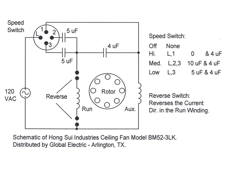
Frustrated by this I decided to bypass the wireless entirely and switch the unit to a typical fan/light dual switch setup on the wall. I figured that the light kit and fan motor itself were still fine so I set to work eliminating the failed fan control module. Having a spare dual-switch for the wall and a third (red) wire already between the electrical boxes made the house wiring part easy, but I still had some work to do modifying the fan. By reading Ken L. Klaser’s article Ceiling Fan Capacitor Solutions I was able to understand the basics of fan speed control, but this this schematic which he linked to was most helpful.
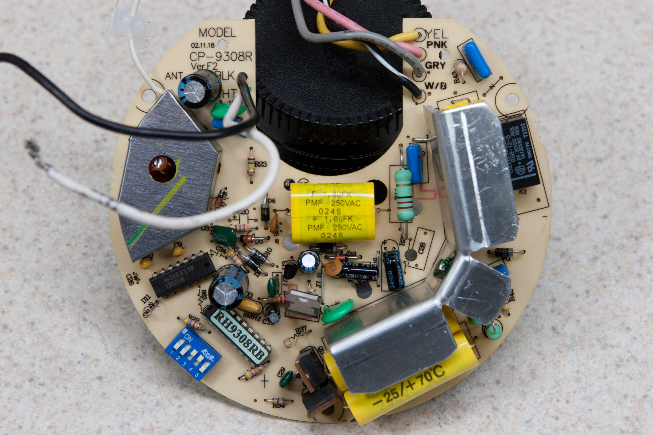
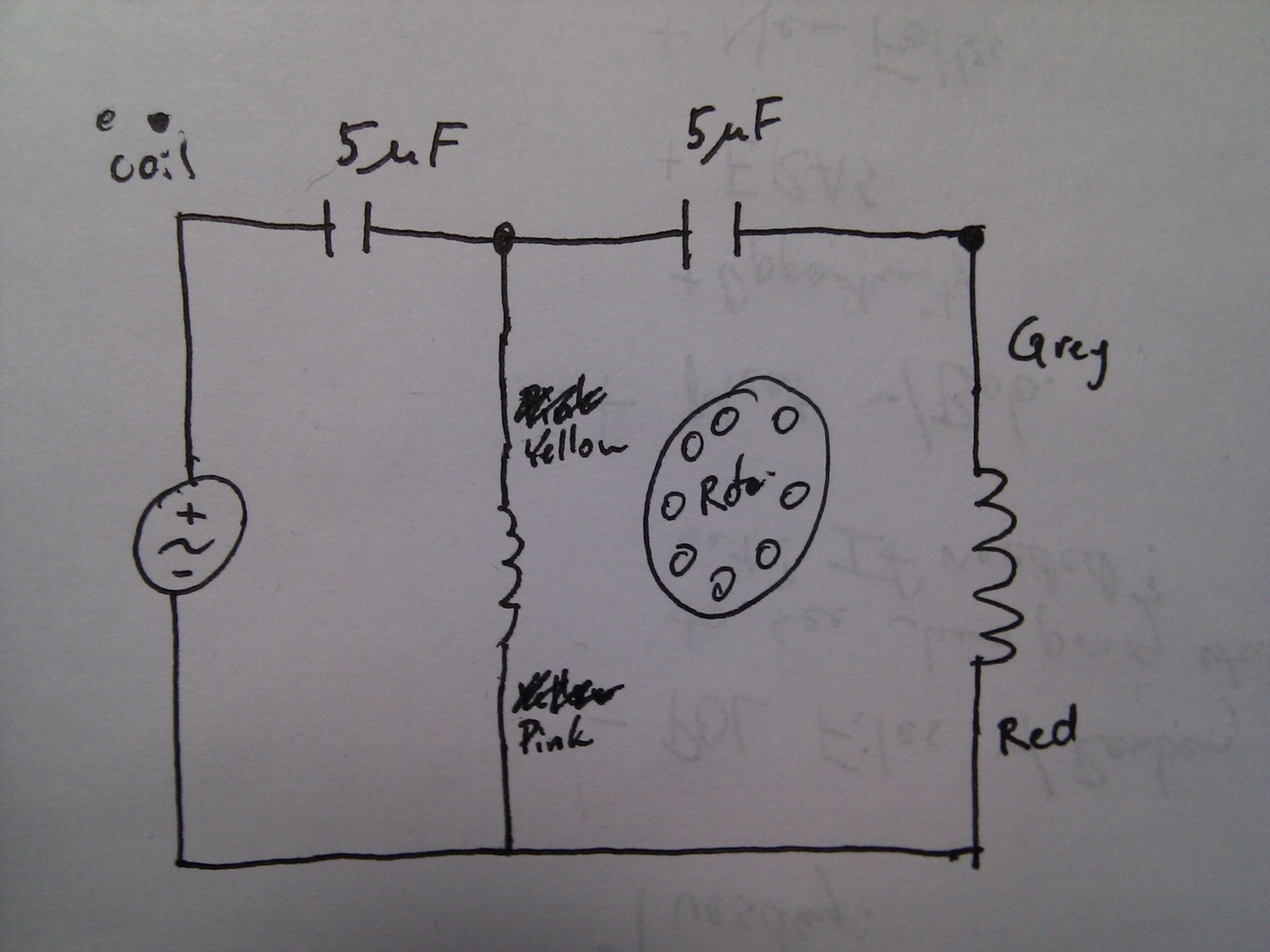
After looking over the control board to understand how the wires to the two coils in the motor were connected I came up with this schematic of how I felt the fan would be powered when set to run slow and in reverse. Removing the capacitors and building a test assembly showed that my initial thought was right, and this resulted in my building the assembly shown above. The fan now runs in reverse and on slow speed when powered and the wireless circuitry has found its place in the trash.
I could have purchased a new selector switch and capacitor assembly to have variable speeds and fitted both it and DPDT switch into the housing to offer the original control selection, but throughout its life the fan was almost exclusively used on low and in reverse, so I didn’t see the need. The fan also looks as it originally did with no new switches sticking out of the side or bits hanging off. I may add these selectors in the future if they are needed, but I don’t see that happening. Thus this was a $0 modification, costing only a few hours of time to learn something new and then redo the wiring.
(Yes, I realize that I should have used a longer piece of clear shrink tubing to better facilitate potting the ends. By the time I realized this I had most of the harness together and decided that simple stress relief and a bit of insulation should be sufficient.)
Cool! A unique solution. Heh. Heh. Get rid of the failed module! “Wire around it.”
You should submit this to Hack-a-day ,it’d beat their usual contrived bits of hackery.
No, wait… Needs more arduino first, and maybe some XBees too to repair the remote using a big ugly plastic box and wires. bonus points for digging holes in your walls.
Ken L. Klaser: Thanks for that article! I was going for the easiest / most elegant solution and that really helped do it.
James: Done! Now to see if they pick it up…
So I dont get this, the it didnt respond for remote and the capacitator was the problem. How is that possible,
wolf: No, actually. It didn’t respond to the remote and I felt the main board was failing, so I reused the run capacitors (which control the fan speed) from the board to make the fan statically set to a particular speed and direction.
its always hard to find circuits for stuff like this. Well done
Colin
colin christie: Thanks, that was the hardest part.
Before this I didn’t actually understand quite what was done to make a fan run at various speeds. On first glance and with everything on the board I thought it might be PWM, but that’d be way too complicated for most fans. Then I learned it’s basically just two run caps.
All the rest of that board is just to receive the wireless signal and insert or remove the caps as needed for the various speeds, or trigger the relay to reverse the fan.
I had the same issue a number of years ago with a relatively new fan. I found three triacs on the PC board and removed them. Soldered a pull chain switch to bypass and had all three speeds. Repair parts were available at the time but, the board was almost as much as the whole fan.
UncleBone: That sounds like a good solution as well. Nice job on that. (As you can tell I’m not too fond of not-high-quality wireless implementations.
I’m attempting a similar mod but I’d like to retain the speeds and reversibility.
One problem: Currently, “Hi” is reversed from Med and Low. Are the capacitors polarized?
Read more: http://ada19851985.proboards.com/index.cgi?action=display&board=problems&thread=5335
Thanks, Davide-NYC
Davide-NYC: Sorry, I can’t tell you why it’s reversed, but the capacitors that I used aren’t polarized. Also, if the capacitors were polarized and you fitted them backward they simply wouldn’t work and/or would fail (possibly catastrophically). If I were you I’d get to understanding how the circuit works then figure it out from there. I suspect you just have two capacitors or some wiring mixed up.
Thank you for posting this! I used your example with a slight variation to have the fan run with a forward (aka downward) direction and in medium speed using all three capacitors. Your schematics and the jpeg were golden!