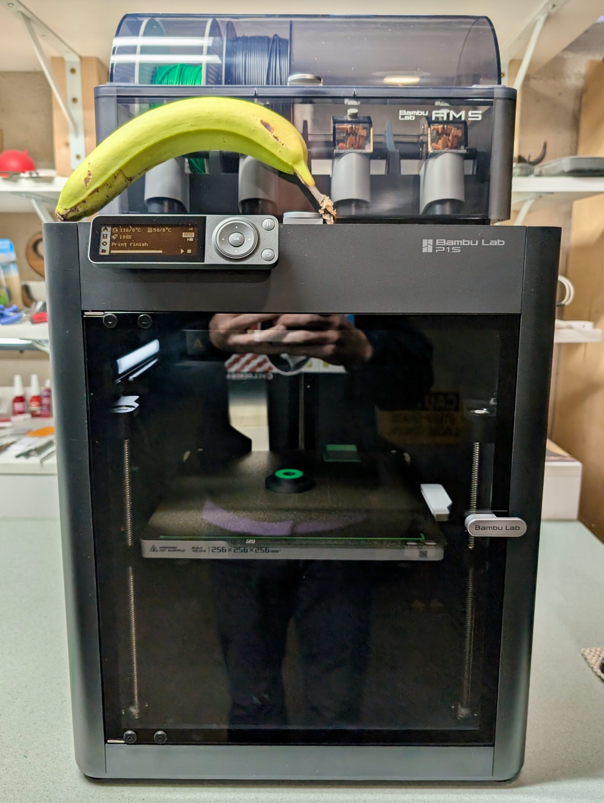
I recently picked up a Bambu Lab P1S 3D Printer for around the house. After staying away from 3D printing for years, the combination of a friend’s experience with this printer (thanks, @make_with_jake!), holiday sales, looking for a hobby, wanting some one-off tools, and a handful of projects where it’d be useful finally got me to buy one. Having done half a dozen prints, thus far I’m pretty satisfied with the output and think it’ll be a nice addition to the house.
This printer, like many other modern devices, is an Internet of Things (IoT) device; something smart which uses a network to communicate. Unfortunately, these can come with a bunch of security risks, and is best isolated to a less-trusted place on a home network. In my case, a separate network,or VLAN, called IoT.
Beyond the typical good-practice of isolating IoT devices to a separate network, I’m also wary of cloud-connected devices because of the possibility of remote exploit or bugs. For example, back in 2023 Bambu Lab themselves had an issue which resulted in old print jobs being started on cloud-connected printers. Since these printers get hot and move without detecting if they are in a completely safe and ready-to-go state, this was bad. I’d rather avoid the chance of this. And really, when am I going to want to submit a print job from my phone or anywhere other than my home network?
Bambu Lab has a LAN Mode available for their printers which ostensibly disconnects it from the cloud, but unfortunately it still expects everything to be on the same network.
I was unable to find clear info on working around this in a simple fashion without extra utilities, but digging into and solving this kind of stuff is something I like to do. So this post documents how I put a Bambu Lab P1S on a separate VLAN from the house’s main network, getting it to work otherwise normally.
The network here uses OPNsense, a pretty typical open source firewall, so all the configuration mentioned revolves around it. pfSense is similar enough that everything likely applies there as well, and the basic technical info can also be used to make this work on numerous other firewalls.
As of this writing (2024-Dec-19), this works with Bambu Studio v1.10.1.50 and firmware v01.07.00.00 on the P1S printer. This also works with OrcaSlicer v2.2.0 and whatever version of the Bambu Network Plug-in it installs. I suspect this works for other Bambu Lab printers, as the P1S has all the same features as the higher end ones (eg: camera) but I can’t test to say for sure. Also, everything here covers the P1S running in LAN Mode. It’s possible that things would work differently with cloud connectivity, but I did not explore this. So, insert the standard disclaimer here about past performance and future results…
Why can’t I just point the software at the printer?
To start, the release notes for Bambu Studio v1.10.0 have a section that says a printer can be added with just it’s IP, allowing it to cross networks:
Subnet binding support: Users can now bind printers across different subnets by directly entering the printer’s IP address and Access Code
This sounds like it’d solve the problem, and is a typical way for printers to work, but no… it just doesn’t work.
Despite having the required Studio and printer firmware versions I just couldn’t make it work. When trying this feature I’d see Bambu Studio trying to connect to the printer on 3002/tcp, but the printer would only respond with a RST as if that port wasn’t listening. Something’s broken with this feature, probably in the printer firmware. Maybe this’ll work in the future, but for now we needed another way…
Atypical SSDP?
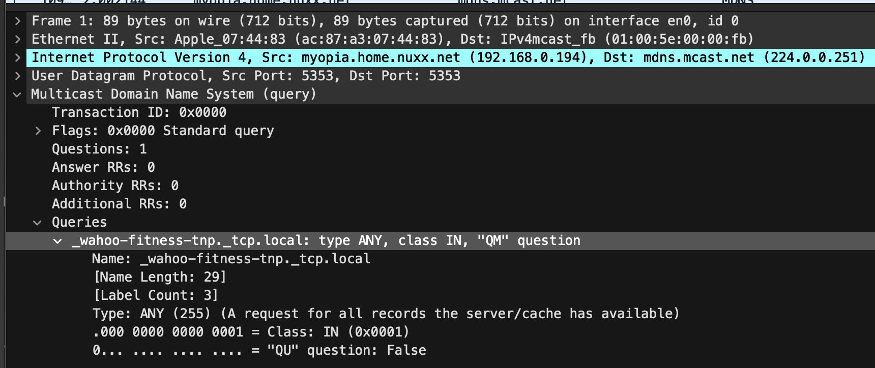
On a single network the printer sends out Simple Service Discovery Protocol (SSDP)-ish messages detailing its specs, Studio receives these and lists the printer. But, SSDP is based on UDP broadcasts, so these don’t cross over to the other VLAN (subnet).
The SSDP part of a packet looks similar to:
NOTIFY * HTTP/1.1\r\n
HOST: 239.255.255.250:1900\r\n
Server: UPnP/1.0\r\n
Location: 192.168.1.105\r\n
NT: urn:bambulab-com:device:3dprinter:1\r\n
USN: xxxxxxxxxxxxxxx\r\n
Cache-Control: max-age=1800\r\n
DevModel.bambu.com: C12\r\n
DevName.bambu.com: Bambu Lab P1S\r\n
DevSignal.bambu.com: -30\r\n
DevConnect.bambu.com: lan\r\n
DevBind.bambu.com: free\r\n
Devseclink.bambu.com: secure\r\n
DevVersion.bambu.com: 01.07.00.00\r\n
DevCap.bambu.com: 1\r\n
\r\n
When Bambu Studio receives this packet it gets the address (Location:) of the printer from the Location section, connects, and all works. But in a multi-VLAN environment we have different networks and different broadcast domains and a firewall in between, so we need two things to work around this: getting the SSDP broadcasts shared across networks, and firewall rules to allow the requisite communication.
These also don’t seem to be normal SSDP packets, as they are sent to destination port 1910/udp or 2021/udp. It’s all just kinda weird… And this thread on the Bambu Lab Community Forum makes it seem even stranger and like it might vary between printer models?
Regardless, here’s how I made this work with the P1S.
Static IP
The P1S (and I presume other Bambu Lab printers) have very little on-device network configuration, receiving network addressing from DHCP. I suggest that you set a DHCP reservation for your printer so that it always receives the same (static) IP address. This will make firewall rules much easier to manage.
SSDP Broadcast Relay
To get the SSDP broadcasts passed between VLANs a bridge or relay is needed, and marjohn56/udpbroadcastrelay works great. This is available as a plugin in OPNsense under System → Firmware → Plugins → os-udpbroadcastrelay, is also available in pfSense, or could be run standalone if you use something else.
After installing, on OPNsense go to Services → UDP Broadcast Relay and create a new entry with the following settings:
- enabled:
✓ - Relay Port:
2021 - Relay Interfaces:
IoT, LAN(Choose each network you wish to bridge the printer between.) - Broadcast Address:
239.255.255.250 - Source Address:
1.1.1.2(This uses a special handler to ensure the packet reaches Studio in the expected form.) - Instance ID:
1(or higher, if you have more rules) - Description:
Bambu Lab Printer Discovery
On my OPNsense firewall, where igb1_vlan2 is my IoT network and igb1 is my LAN network, the running process looks like: /usr/local/sbin/udpbroadcastrelay --id 1 --dev igb1_vlan2 --dev igb1 --port 2021 --multicast 239.255.255.250 -s 1.1.1.2 -f
(Of course, in the event you have any firewall rules preventing packets from getting from the printer or IoT VLAN to the firewall itself — say if you completely isolate your IoT VLAN — you’ll need to allow those.)
Now when going into Bambu Studio under Devices then expanding Printers, the printer will show up. It may take a few moments as the printer to appear as the SSDP are only periodically sent, so be patient if it doesn’t appear immediately.
(Note that if other models of printers aren’t working, it may be useful to also relay port 1910. The P1S works fine with just 2021, so for now that’s all I’ve done.)
Firewall Rules
With Studio seeing the printer, and presuming that your regular and IoT VLANs are firewalled off from each other, rules need to be added to allow the printer to work. While Bambu Studio has a Printer Network Ports article, it seems wrong. I am able to print successfully without opening all the ports listed for LAN Mode, but I also needed to add one more that wasn’t listed: 2024/tcp.
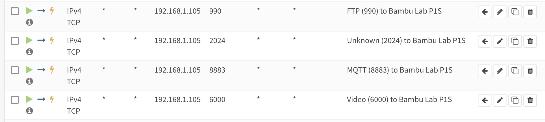
Here’s everything I needed to allow from the regular VLAN to IoT VLAN to have Bambu Studio print to the P1S, along with what I believe each port to handle:
- 990/tcp (FTP)
- 2024/tcp to 2025/tcp (Unknown, but seems to be FTP?)
- 6000/tcp (LAN Mode Video)
- 8883/tcp (MQTT)
Nothing needs to be opened from the IoT VLAN, everything seems to be TCP and the stateful firewall seems to handle the return path. (Even though the Printer Network Ports article with it’s 50000~50100 range for LAN mode FTP implies active mode FTP…)
And with that, it just works. I can now have my Bambu Lab P1S on the isolated IoT VLAN from a client on the normal/regular/LAN VLAN, printer found via autodiscovery, with only the requisite ports opened up.
Missing Functionality? Leaky Data?

Note that there are a few functions — like browsing the contents of the SD card for timelapse videos or looking at the job history — which only work when connected to the cloud service. This really surprises me, as I can think of no rational reason why this data should need to be brokered by Bambu Lab.
Unless they want to snarf up the data about what you print and video of it happening and when and… and…?
Digging into that sounds worthy, but is a project for another time. It’s a pretty good reminder of why isolating IoT devices is good practice, though. For now I’ll just manually remove the SD card if I want access to these things. And consider if maybe I should completely isolate the printer from sending data out to the internet…
Citations
Big, big thanks to Rdiger-36/StudioBridge and very specifically the contents of UDPPackage.java. This utility which helps find Bambu Lab printers cross-VLAN by generating an SSDP packet, and sending it to loopback, saved me a bunch of time in figuring out how Bambu Lab’s non-standard SSDP works.
All the discussion around issue #702, Add printer in LAN mode by IP address was incredibly helpful in understanding what was going on and why this printer didn’t seem to Just Work in a multi-VLAN environment. This thread, and watching what StudioBridge did, made understanding the discovery process pretty simple.
And as much as I dislike the AGPL in general, it worked out really well here. I wouldn’t expect a company like Bambu Lab to release their software so openly, but with the AGPL they had to. Slic3r begat PrusaSlicer which begat Bambu Studio which begat OrcaSlicer giving us a rich library of slicers…
Updates
2024-Dec-22: After this worked fine for a few days I ran into problems printing from OrcaSlicer where jobs wouldn’t send. Digging I found that 2025/tcp was needed as well, so I updated the article above. It seems this is another FTP port? It’d sure be nice if this was documented.
Comments closed