Press "Enter" to skip to content

Month: December 2025

Home Assistant as Personal Device Tracker

Last two years of my phone’s location, as gathered by Home Assistant.

Part of our Home Assistant (HA) setup uses the Companion Mobile App for easy remote control and to collect data from our devices. The main tracked item is the phone’s location, so HA can tell if we’re home or not, and currently I only use it to change how some lighting automations work.

I also have HA set up to log all device state data (switches, outlets, climate sensors, power consumption) to a local instance of InfluxDB, and then have Grafana installed so I can visualize this data.

Mains Voltage via Home Assistant from February 2024 through December 2025.

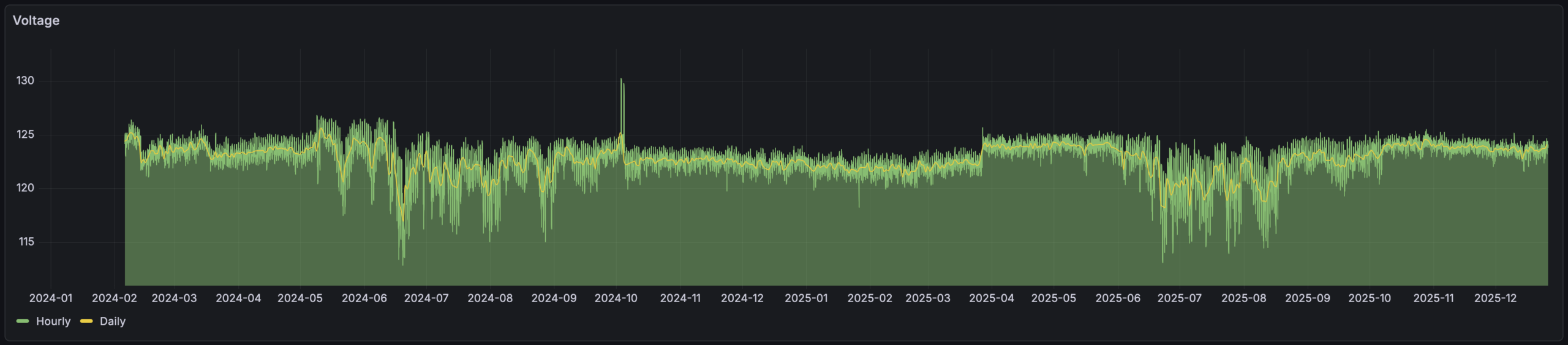
My original use for this was long-term logging of temperature and humidity sensor data — which is neat to see — but as I’ve experimented with graphing things like mains voltage. This was neat because it made it easy to see things like how voltage drops and becomes erratic during summertime cooling periods. And showed that grid voltage jumped up by ~2VAC in March 2025, around which time I recall DTE doing utility work on the grid just north of our house. (Yes, evidence of them improving things locally.)

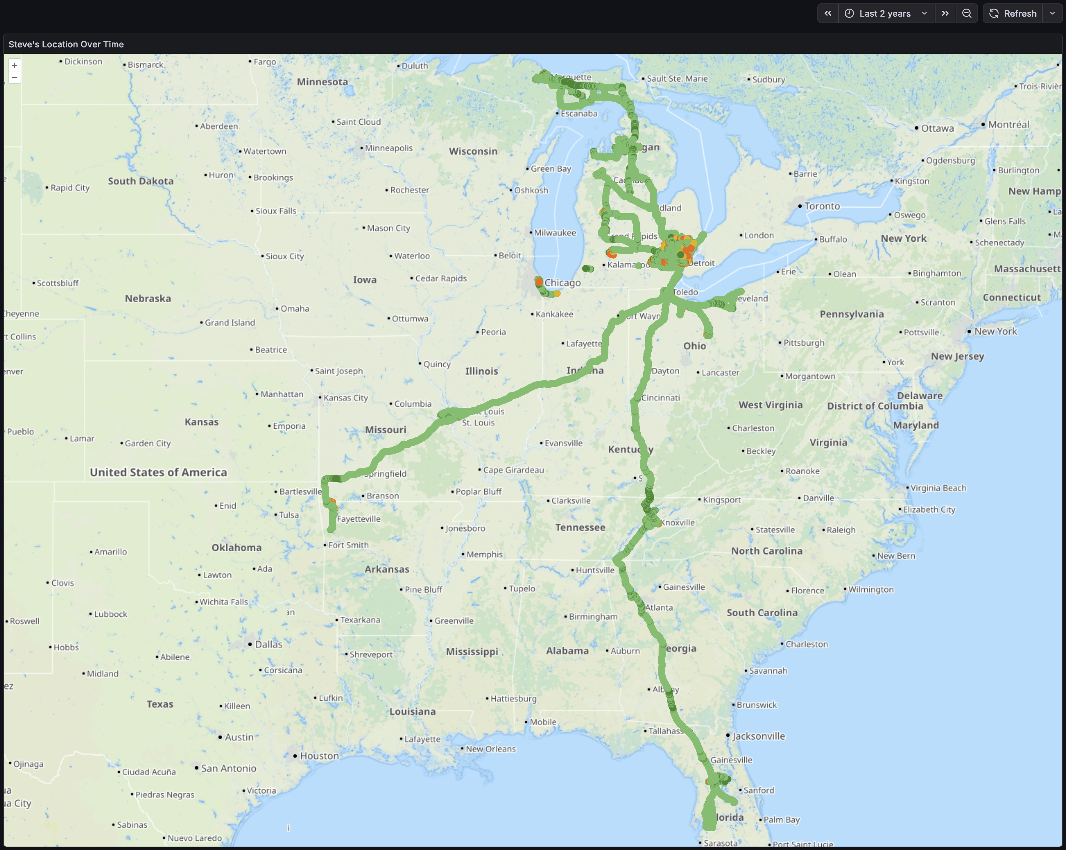
Late on Christmas evening, wanting some time to just sit alone and do things, I put together a map showing where my phone had been. I’m pretty happy with how it came out, as I can now input a time range and dots will appear for each logged location, color-coded with geopositioning accuracy (brighter green is more accurate).

I also used this as another exercise in working with LLM tools like ChatGPT. I’m (finally?) realizing how useful this can be when thought of as a modern search engine. There’s still constant reminders of how imperfect and problematic results can be, but with a domain background it’s helpful. I find that thinking of these tools as tireless (yet emotionless) junior employee who makes lots of mistakes and needs all responses tested and vetted works… decently… in pointing me in a decent direction.

But I digress… Here’s the query that’s the main point of this and makes it all go:

SELECT "latitude", "longitude","gps_accuracy"
FROM "homeassistant"."autogen"."state"
WHERE "entity_id" = 'pixel_8'
AND $timeFilter
AND "gps_accuracy" < 100
Last 30 days of phone location data.

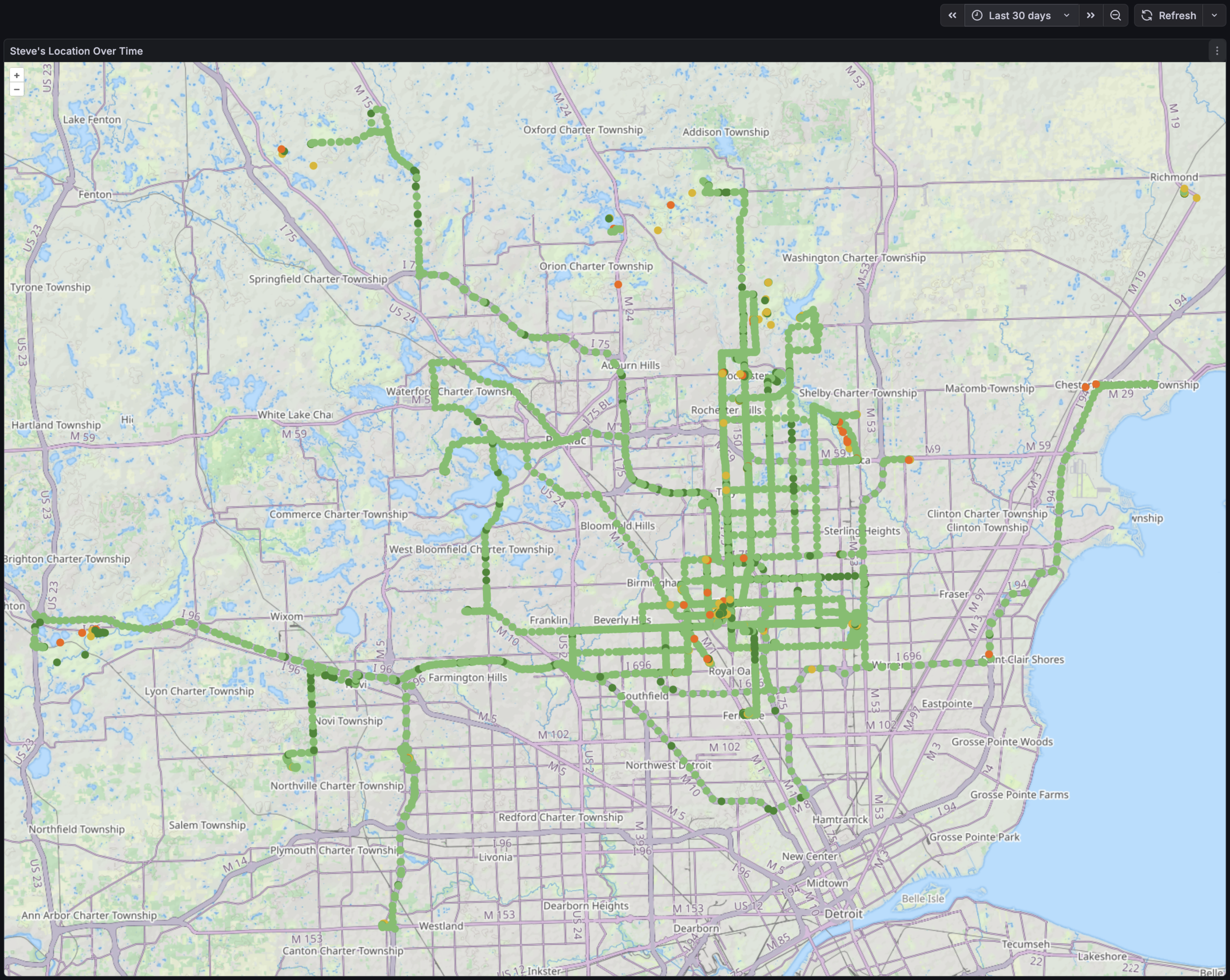
It was then simply a matter of putting this into a Geomap that displays a point for each location, and colors it based on gps_accuracy state and looks decent. I was even able to place it all on the Thunderforest Landscape map tiles which shows OSM-mapped trails and has been oh-so-useful on my RAMBA Trails Map.

Initially I looked at a heat map, but it didn’t seem as useful as individual points. I may explore this later, but the device where I’m currently running HA is a bit under-powered for this. And note that the query above excludes records that have a GNSS accuracy worse than 100 meters as this generally means that GPS (et al) wasn’t working at all and geopositioning likely came from local mobile towers (which shows me as being on tall local buildings, in fields I’d never visit, etc).

While obvious in retrospect, the most notable things this shows me is that when I’m driving — typically running OsmAnd+ or Google Maps (or both) — the recorded points are high accuracy and frequent. When riding my bike, carrying my phone idly in a pocket, the GNSS sensor is likely PRIORITY_PASSIVE so the dots are both infrequent and low accuracy.

It’s also just neat to look at. Things jump out like a trip to IKEA in Canton, riding at Island Lake and Holly Wilderness, etc.

I’m curious to see what I can further tease out of the logged data. The HA Companion mobile app can get all sorts of interesting info via its Sensors. For example, the Activity Sensors on iOS automatically detect:

  • Stationary
  • Walking
  • Running
  • Automotive
  • Cycling

And on Android:

  • in_vehicle
  • on_bicycle
  • on_foot
  • running
  • still
  • tilting
  • walking

Plus there’s things like what’s being done with the device, what’s seen about its environment (including visible wireless networks, Bluetooth devices), etc…

It might be neat to see what more I can get out of this. Or it might just end up as a nudge to decrease what HA is collecting (and possibly purge some of it from the db).

Of course, it pales in comparison to what the telcos, device manufacturers, OS vendors, and app vendors can do with their data engineers, massive troves of data and ability to cross-reference, etc. (A bit of a reminder that phones are just behavior-trackers that also make calls and take pictures…)

I hope to soon try migrating this HA instance from a Raspberry Pi 4B to a higher-powered slim PC. While I don’t intend to take this much further, it will provide more power for chewing on data like this and will hopefully let me figure out a disaster recovery plan for HA that includes preserving all logged data. When first setting up this map I tried to draw both a location and heatmap and this was a little too much for the Pi and as it ground to a halt Kristen noticed that the back yard lights weren’t turning on properly. Doh! Or I guess I could just do the processing on another machine…

Comments closed

OpenSCAD Is Kinda Neat

Designing a simple battery holder in OpenSCAD.

Earlier this year I designed a very basic box/organizer for AA and AAA batteries in Autodesk Fusion, making it parameterized so that by changing a few variables one could adjust the battery type/size, rows/columns, etc. This worked well, and after uploading it to Printables earlier today I realized that reimplementing it would probably be a good way to learn the basics of OpenSCAD.

OpenSCAD is a rather different type of CAD tool, one in which you write code to generate objects. Because my battery holder is very simple (just a box with a pattern of cutouts) and uses input parameters, I figured it’d be a good intro to a new language / tool. And in the future might even be better than firing up Fusion for such simple designs.

After going through part of the tutorial and an hour or so of poking, here’s the result: battery_holder_generator.scad

Slicer showing the Fusion model on top and OpenSCAD on bottom.

By changing just a few variables — numRows and numColumns and batteryType — one can render a customized battery holder which can then be plopped into a slicer and printed. No heavy/expensive CAD software needed and the output is effectively the same.

Without comments or informative output, this is the meat of the code:

AA = 15;
AAA = 11;
heightCompartment = 19;
thicknessWall = 1;
numRows = 4;
numColumns = 10;
batteryType = AA;

widthBox = (numRows * batteryType) + ((numRows + 1) * thicknessWall);
lengthBox = (numColumns * batteryType) + ((numColumns + 1) * thicknessWall);
depthBox = heightCompartment + thicknessWall;

difference() {
    cube([lengthBox, widthBox, depthBox]);
    for (c = [ 1 : numColumns ])
        for (r = [ 1 : numRows ])
            let (
                startColumn = ((c * thicknessWall) + ((c - 1) * batteryType)),
                startRow = ((r * thicknessWall) + ((r - 1) * batteryType))
            )
            {
                translate([startColumn, startRow, thicknessWall])
                cube([batteryType, batteryType, heightCompartment + 1]);
            }
};

Simply, it draws a box and cuts out the holes. (The first cube() draws the main box, then difference() subtracts the battery holes via the second cube() as their quantity and location (via translate()) is iterated.

That’s it. Pretty neat, eh?

(One part that confused me is how I needed to use let() to define startColumn and startRow inside the loop. I don’t understand this…)

While this probably won’t be very helpful for more complicated designs, I can see this being super useful for bearing drifts, spacers, and other similar simple (yet incredibly useful in real life) geometric shapes.

Comments closed

Solar Radiation (Sun) Shield for Temperature Sensors

Solar radiation (sun) shield mounted to the chain link fence.

I have temperature/humidity sensors in the back yard, both for Home Assistant and a La Crosse “atomic clock” on the wall of my office. These had been mounted nicely in the shade on a north-facing post on our old wooden fence, but after the fence was replaced I needed to find somewhere else to put them. The first place I tried, the back side of a utility pole, was too close to the fence and they’d read overly-warm in the evenings as the sun was hitting it. (And had the legal issues around mounting things on a utility pole.)

There are myriad different “solar radiation shields” available either for purchase or 3D printing, but they are generally designed to hold one sensor and be mounted on a pole, get held together with bolts, or just aren’t a great design.

La Crosse TX141-BV4 and ZOOZ ZSE44 inside shield.

I needed to hold two (or more) sensors and being a bit bored (because we’re in the crappy onset of winter here), I designed this, which is available here on Printables: Solar Radiation Shield for Outdoor Temperature Sensors (Variable Height w/ Chain Link Fence Mount

(Or you can download the files here: radiation_shield_for_outdoor_sensors_v1.zip)

I’m really happy with how it came out. In the end it’s a simple two-piece (plus mount) design, with one being the roof and the other a body piece. Each body piece is 15mm tall so I printed off the requisite number to hold my sensors (nine), one roof, and stuck it all together with J-B Weld PlasticBonder epoxy. Pegs and holes align the pieces and make it easy to glue together.

The vents offer shade all the way to horizontal while still having massive openings, so I think it’ll work well. The roof is a bit more translucent than I cared for, but by lining it with some foil tape it’s now nicely opaque. I’m not concerned about the transparency of the vent slots, but may add tape later or re-print with a different filament if it seems to be a problem.

Currently I have La Crosse TX141-BV4 and ZOOZ ZSE44 sensors installed, but may add others as I want to replace the ZSE44 with something that reads negative values. The sensors are held in place using 3M VHB 4910, which is easy to remove (by sawing through with dental floss then rolling off with a finger) but otherwise holds very firmly, especially against shear loads. It’s also thick enough to fit between the ribs on the back of the ZSE44 mount. And I had it on hand.

Chain link fence post mount, with VHB 5925 for additional support.

I initially designed this to use QUEEN SIZE BrickClip fasteners and hang it off the north-facing side of the chimney. Due to the weight of the assembled unit with sensors (~350g) and wanting to keep it away from the house’s thermal mass, I designed a chain link fence post mount. This allowed me to place it quite close to where the sensors previously had been, a nicely shaded yet breezy location. The designed-in slot (originally for BrickClips) just happened to allow easy addition of other mounts.

The entire unit was attached to a chain link fence post using black UV-resistant cable ties and with 3M VHB 5925 tape for a bit of additional stability. This tape works well but also was chosen because I had it on hand and it’s nice and thin. While this is a strong adhesive it’s really only needed for a bit of friction to keep the mount from twisting on the pole if bumped.

So how does this one differ from the other designs I came across? Or, differently stated, why did I bother making my own?

  • Sensor-Agnostic: Flat platform allows any sensor to be stuck in place. Most designs are for a single sensor type.
  • Larger: Most other designs only hold one sensor. I wanted to hold two or three.
  • No hardware: Many other designs are held together with bolts. I’m fine with gluing it together as this makes everything else simpler.
  • Flexible Mounting: A simple 15mm x 5mm notch in the back both allows BrickClip fasteners to be used while also a simple platform for integrating other mounts (such as the chain link fence mount).
  • Full Body Support / No Arm: Many other mounts replicate the shield-on-an-arm design of commercial pole mounts. I am concerned about FDM printed thermoplastic sagging, so either this needed to be metal, or the support done differently. I also had no need for a pole mount.
Comments closed

Riser Feet for Wahoo KICKR CORE 2

+14mm custom-made riser foot on my Wahoo KICKR CORE 2.

The Problem and Solution

My new trainer, a Wahoo KICKR CORE 2, has the rear axle that’s ~322mm above the floor. With anything larger than a 700c x 25mm front tire this puts the front wheel higher off the ground, which screws with the bike’s geometry including the all-important saddle position. After a bit of measuring I found that raising the trainer ~14mm would make things level on our floor, and having a 3D printer and a wee bit of design skill, I decided to make replacement feet that’d put it at the height I wanted.

This is the result, 3D printable feet which replace the stock rubber ones, securing in place with the same set screws, and can be printed in whichever height is needed.

Final prints of the four riser feet for my trainer.

You can find the .STL files for +5mm to +50mm in 5mm steps, a Bambu Studio project containing all the sizes, and a parametric Autodesk Fusion project allowing you to generate your own custom height riser feet. (Just change liftAdditional.)

This is all licensed CC BY-NC so one can make them, change the design, whichever… You just can’t sell them:

Wahoo Fitness KICKR CORE 2 Riser Feet at Printables

(If you really do want to sell them, email me and we’ll work something out.)

These printed wonderfully using Overture PETG at slow print speeds (50mm/sec) in a Bambu Lab P1S with all fans off and temperatures on the high end of the specified ranges. (I am curious how TPU would work out for printing these as it should be more rubber-like…)

Design Lessons

Development prints, including tests of screw hole size and size indicator types.

The main point of this post is to document a few things I learned while designing this. Big, big thanks to my friend Jake Drews — who sells a number of similar products on Etsy as Cycl3dCo — for talking through some design ideas with me.

So what did I learn?

  • I wanted to have parametric text on the bottom of the printed surface to show the lift. After experimenting with a second color for style and indication — which was not a great way to go — I settled on using a groove for design, and wanted a single line font as a similar groove. (These print well, akin to a 45° chamfer.) It turns out that single line fonts in Fusion need to be exploded before they can be swept to make a groove. Exploding a font makes it no-longer parametrically controlled.
  • The simpler solution ended up being putting the height inside the leg as 0.5mm raised text, sized to sit inside the tube of the leg, and leaving the groove on the outside as a decorative feature. After all, one doesn’t need to see the height all the time, but it is good to have the parts marked. This works out better all around. Leaving the end just blank looked boring.
  • If you can avoid multi-color printing, it’s probably better, as it’s less wasteful, many people don’t have multi-color printing setups, etc.
  • Adding an inset of 0.01mm will make it easy to color in the slicer (OrcaSlicer or Bambu Studio), but if not colored, is small enough that it’ll be ignored by the slicer. This is a good way to make optionally-multi-colored designs. (Note that my final design didn’t use this, but it’s a good-to-remember technique.)

New trainers?

A few months back there was a great sale on the Wahoo KICKR CORE 2 trainers, and while Kristen and I had some problems with Wahoo in the past, the price was low and the new features would solve some problems, so we both decided to buy them. Specifically:

  • Wi-Fi Connection / Kickr BRIDGE: Kristen and I both use an Apple TV (ATV) for Zwift, and the number of Bluetooth (BT) connections on the ATV is limited to two. This meant we could use Trainer + Cadence, or Trainer + Heart Rate Sensor (HR), or Trainer + AirPods. All very limiting. With the CORE 2 it can communicate via Wi-Fi and also bundle the HR data in, freeing up the ATV’s BT channels for other things, such as the Zwift Click controllers and AirPods. It also feels more reliable, and has been very nice.
  • Virtual Shifting / Zwift Cog and Click: Via smart use of the smart trainer features, the CORE 2 supports virtual shifting with a single cassette cog. This eliminates wear on more expensive drivetrain parts (cassette), makes it easier to take the bike on and off, and results in a near-perfect chainline so things are simply quiet. While it took me a few rides to get accustomed to virtual shifting, it’s pretty nice and feels similar to actual shifting steps, but without the noise or wear.
  • Noise: Simply put, the CORE 2 with the Zwift Cog is quiet. Unlike her older CyclOps Hammer, I can’t hear her riding. This might not sound like much, but the Hammer had a steady whine that I could hear throughout the house. It’s pretty much only the rattle of the chain passing over the cogs and noise from the blower fans.
  • Weight/Balance: Kristen uses her trainer on a KOM Cycling Indoor Rocker Plate RPV1. With the older Hammer it’s heavy, asymmetric design made the whole assembly list to one side unless she put a 15 pound weight on the rocker plate opposite the trainer. The CORE 2 is more symmetric and lighter and simply doesn’t have this problem.

All around, they worked out to be nice upgrades, and we were able to easily sell our older trainers for fair prices. For a bunch of details on these trainers give this DC Rainmaker review a read.

Comments closed