SDrive NUXX
About
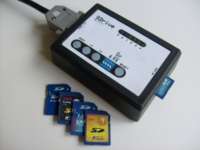
In October 2008, Robert Petružela (Bob!k) & Radek Štěrba (Raster) of the Atari group C.P.U. released the firmware, schematic, and other related documents for their SDrive project. This device "...connects to Atari XL/XE's serial (SIO) port and simulates an Atari floppy disk drive with full read/write access to programs and data stored on a SecureDigital flash card (SD)."
Having recently imaged the Atari floppy disks from when I was growing up I found this project immediately attractive, and wanted to build an SDrive so that I could more easily use the created images with my original 800XL. However, I wanted to expand on the SDrive, with features such as a different enclosure, SIO connector, and an easier to build design. As C.P.U. did with the original SDrive, I wanted to make my work available to everyone so that anyone wishing to build on my work can do so freely. The result of this desire is the project documented here: SDrive NUXX, an adaptation of SDrive by C.P.U.. All final design documents that I created for this project have been released under a Creative Commons license for everyone to use.
Design
C.P.U.'s Original SDrive
These are the SDrive's original features, quoted from the original SDrive by C.P.U. page:
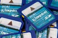
- Supported flash cards: SecureDigital up to 2GB size, FAT16 filesystem
- Maximum number of drives: 4 (D1: to D4:) + 1 special boot drive
- Supported SIO transfer rates: 3.5 to 128kb/s (standard 19 and 69kb/s)
- Supported disk images: ATR, XFD, size up to 16MB, 128 or 256B sectors
- Supported executable files: COM, XEX, BIN.... (any filename extension).
- Device controlled by software running on Atari from the SD card, which can be therefore easily updated/replaced
- Drives swappable on the fly by buttons
- Write protect/enable switch
- SDrive ID number selection switch - simultaneous use of up to 4 SDrives
- Low cost design – no LCD, a few LEDs, cheap DIL28 Atmega8 MCU, single sided PCB*
- Firmware and software sourcecode freely available
When C.P.U. released the original SDrive information on their site, it was accompanied by a file SDrive081012.zip containing schematics, firmware, applications, photographs, documentation, and source code related to their project. This open-source information is invaluable, and without it the SDrive NUXX would not have been possible. A mirror of this file can be found here: SDrive081012.zip.
During the final phases of the SDrive NUXX development, C.P.U. released some updates to the SDrive, including different fuse programming recommendations and a new control program for the SDrive. These changes are encompassed in SDrive20090403.zip, which I have mirrored here: SDrive20090403.zip.
It is strongly advised that one review these file, particularly the SDrive_en.pdf documentation which covers the use and operation of the SDrive. All efforts have been made to ensure that the SDrive NUXX's function is identical that of the original SDrive.
SDrive NUXX Changes
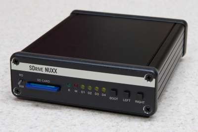
The first, and most obvious change from the original SDrive, is the use of a readily available enclosure and custom end panels with cutouts and artwork. These changes imply a different PCB and component layout, which include slightly modified control layout.
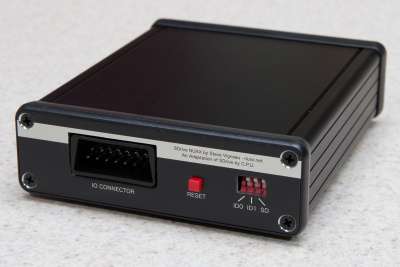
The second change with the SDrive NUXX design is the use of an SIO connector footprint. This allows a standard Atari SIO connector to be used, allowing easy connectivity with any of the compatible Atari 8-bit computers.
Third, the new PCB design incorporates a low-cost AVR programmer allowing a SDrive builder who doesn't have AVR programming hardware readily available an easy method of loading the firmware on the microcontroller. Adding this programmer to the board adds only a few dollars to assembly cost, with the vast majority of that being in the DB25 connector.
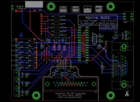
PCB
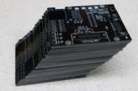
The SDrive NUXXs PCB was laid out in the Standard version of CadSoft EAGLE with all routing done by hand. These boards were then manufactured with black soldermask and hot air solder leveling finishing, providing both a cost effective and attractive board. Except for the SD connector, which is only available in surface mount, all components for the SDrive NUXX are through-hole, making assembly as easy as possible. Additionally, while the SD connector is a surface mount part, its design of completely exposed pins and mounting tabs, and small plastic posts on the underside make aligning the part and soldering it easy, even for someone who has never done surface mount work in the past.
SIO Connector
For easiest connection to an Atari 8-bit computer, the SDrive NUXX PCB has added a footprint allowing one to fit either an original SIO connector to the board or the original (from the SDrive) DB15. This part footprint, or package in EAGLE parlance, was drawn with measurements taken from a JAE D03 (thick, narrow wing) and validated against four other thin, wide wing SIO connector types. A few variants on this package are available in atari_sio_part_for_cadsoft_eagle.zip.
While soldering the SIO connector to the PCB provides sufficient mechanical retention, it may be desirable to screw the connector down. For the thin, flat-wing, more easily molded connectors a 4-40 machine screw / locking nut set (such as McMaster-Carr part numbers 91772A107 and 91831A005) must be used as there is not enough plastic available in the connector for a screw to bite into. When using the JAE D03 SIO connector with thicker plastic wings, some thread-cutting screws for plastic (McMaster-Carr part number 94629A550) should be used to fasten the connector to the PCB.
This SIO connector footprint is placed on the PCB directly in line with the DB15 connector, allowing the builder their choice of SIO or DB15 connector. The SIO to DB15 connection pinning is as found in the original SDrive, which is detailed in Radek Štěrba's SIO D-SUB15M standard Atariklub PV article (Česky, Google Translation to English).
Programmer / Header
In the package of files for the original SDrive, schematics are provided for Jerry Meng (BA1FB)'s Simplified AVR ISP Programmer. This simplification of the Atmel STK200 into one connector and four resistors can easily flash many Atmel AVR microcontrollers. To make programming of the ATmega8 microcontroller easier, this programmer has been included on the SDrive NUXX PCB. If one doesn't wish to use the on-board programmer, parts J2, R14-R17, and potentially J3 may be omitted.
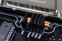
To keep the programmer isolated from the SDrive NUXX during normal use of the device, two rows of pin headers are fitted on the PCB. One half is the normal programming header for the ATmega8, and the other is part of the Simplified AVR ISP Programmer. To connect the programmer to the microcontroller, one simply has to fit five standard .100" jumpers across the pins as seen in this photo. The board can then be connected to a PC's parallel port and the microcontroller programmed.
Note that an SD card should not be in the SD slot during programming of the microcontroller.
Revisions
v1.1: Production version. Changes from v1.0 are as follows:
- Added missing traces between pins 2 and 12 and pins 3 and 11 of J2.
- Rearranged Right/Left/Boot labels on SW1-SW3 to match what the switches actually do.
- Fixed (reversed) part outline for IC1.
- Moved SW1-SW4 0.5mm closer to the panel edge to take into account the new, thicker end panel material.
- Made D1 lead spacing wider to match resistors (and facilitate using lead benders).
- Moved IC2 et al to make more room for future development work.
- Optimized numerous routes.
- Resized version / model plate on bottom to match documentation layer.
v1.0: Prototype version, not distributed publicly.
Enclosure
Chassis
Hammond Manufacturing's 1455-series enclosures, the 1455L1201BK was selected as the enclosure for this project. This extruded aluminum enclosure is strong, attractive, available in both black and silver (natural), and reasonably priced. The black version (BK part number suffix) is the standard part used for the SDrive NUXX.
This case ships with rubber feet, self-tapping screws, plastic bezels, and metal end panels. The metal end panels are discarded in place of the custom end panels, but the rest of the mounting hardware is used to hold the SDrive NUXX PCB snugly in the card guides and against the end panels.
End Panels
The end panels for the SDrive NUXX are made out of photo sensitive aluminum material known as Metalphoto. This material is then laminated on to a thicker aluminum sheet and drilled / punched to produce the final panels. These custom end panels were designed based on dimensions provided by Hammond Manufacturing in their 1455L1201BK data sheet and are manufactured by [url=http://www.mpofcinci.com/]Metalphoto of Cincinatti[/url].
The original Hammond Manufacturing end panels, provided with the case, are 1.5mm thick. In order to have a sufficiently rigid end panel, ~2mm pieces were selected for the SDrive NUXX. These panels fit into the plastic bezels which ship with the enclosure and fasten down using four self tapping #6 screws. These screws come with the enclosure.
Keycaps
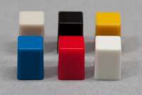
The Omron B3F-3150 tactile switches used in the SDrive NUXX have a number of different keycaps available. In order to fit in the production front panel, the B32-10xx key caps must be used. Typically three black keycaps (Omron B32-1010 / Digi-Key SW451-ND) are used in the front panel and one red keycap (Omron B32-1080 / Digi-Key SW252-ND) are used, although a number of other colors may also be used. This image shows the Light Grey, Black, Yellow, Blue, Red, and White keycaps.
Here is a list of all the Omron B32-10xx keycaps carried by Digi-Key at the time this article was last updated:
Assembly Tips
PCB
- When soldering the SD card, be careful that there aren't bridges made between any of the pins and the housing.
- Be sure to align all LEDs and the toggle switch straight with the front edge of the PCB. This will ensure that they fit nicely through the holes in the front panel.
- The tactile switches snap into place and set nicely against the PCB. Be careful that they are seated nicely and not pointing up or down, otherwise the keycaps will not fit nicely through the panels.
- Solder the following parts, in this order, using water-soluble flux, before washing the PCB:
- SD Card Slot
- DIP Socket (IC2)
- D1 - Diode (D1)
- All Resistors
- J3 - Pin Header
- Q1 - Crystal
- All Capacitors
- IC1 - LDO Voltage Regulator
- All LEDs
- SW5 - DIP Switches (If Washable / Taped Part Selected)
- Wash the flux from the PCB with hot water then dry thoroughly. See this article on flux removal for more information.
- Screw the SIO connector in place before soldering. This lets you ensure that the alignment is proper before any soldering is done.
- Solder the remaining parts with no-clean flux:
- All Tactile Switches
- SW6 - Toggle Switch
- J2 - DB25 Connector
- J1 - SIO or DB15 Connector
- SW5 - DIP Switches (If non-Washable / Unsealed Part Selected)
First Power Up
- Before the first power up, check for shorts between the 5V and 3.3V rails and GND. If a short is found be certain to correct it before powering up the board. Next power up the board without an SD card or IC2 (ATmega8) fitted and check the 5V and 3.3V rails at the test points TP1-TP3 to be sure they are at proper levels.
- After ensuring that power is correct, power down the board, insert IC2, and, if needed, program it.
- Be sure that the DIP switches are all in the up / open position. This will turn off the SD Lock Override and set the SDrive NUXX to ID0, which is appropriate when only one SDrive is connected.
- Note that if something goes wrong and the smoke is let out of a component during testing, all the smoke must be collected, reassembled, and reinserted before the part will work again. It is often easier to replace the failed component.
Assembly
- Close up by fitting the rear panel, inserting the PCB, fitting the front panel. This avoids inadvertently damaging the front panel and toggle switch on the work surface.
- Ensure that the top panel is in place before fitting screwing in the screws, as they occasionally impede on the channels which the top panel fit into.
- When pressing the front panel down over the LEDs and toggle switch, be sure that everything is lined up before applying any force. If things are off the parts won't align nicely and one risks bending an LED or expensive toggle switch.
- Don't overtighten the case screws. They are self threading and capable of stripping out the channels which they fit into.
Programming the ATmega8
When using the on-board programmer to program the ATmega8 microcontroller (IC2), it is suggested that either PonyProg2000 or avrdude (part of the WinAVR suite) be used. In order to program the chip in-circuit, the SDrive NUXX PCB must be powered up. This power can be obtained by either from an Atari via the SIO connector or from an external power supply connected directly to the PCB (see the schematic for details of where to insert power).
Jumpers must also be fitted across J3 to connect the programmer circuit to the SDrive circuit. After programming it is suggested that these jumpers be removed, to keep the length of the SD data lines as short as possible.
Ensure that the SD card slot is empty during programming, as some of the SD card's data lines are shared by the programmer.
Firmware
The following two files, taken from either the SDrive081012.zip or SDrive20090403.zip packages, are used to program IC2 in the SDrive NUXX:
- FLASH: SDrive.hex (MD5: 4469145fa8018e336dbf3431ae82a86e)
- EEPROM: SDrive.eep (MD5: 8ee46ccd9d32867a6ccc049f1146e768)
PonyProg2000
To program IC2 with PonyProg2000 2.0.7c Beta under Windows, perform the following steps:
- Install and launch PonyProg2000.
- Run calibration via Setup → Calibration and ensure that calibration runs successfully.
- In Setup → Interface Setup select Parallel, Avr ISP I/O, LPT1 (or whichever parallel port you are using).
- Click Probe and ensure that the probe is successful, displaying Test Ok, indicating that the programmer has been found. Click OK twice to return to the main window.
- Select File → Open Program (FLASH) File... and open the SDrive.hex file.
- Select File → Open Data (EEPROM) File... and open the SDrive.eep file.
- Select Command → Write All to write the data to the FLASH and EEPROM portions of IC2.
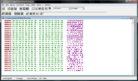
- Select Command → Security and Configuration Bits... to display the Security and Configuration bits dialog. As in this image, uncheck all check boxes except for SPIEN (which may be grayed out), BODLEVEL, and BODEN, then click Write.
If all of these steps complete successfully, the ATmega8 (IC2) on your SDrive NUXX is now programmed and ready for use.
WinAVR / avrdude
When using WinAVR / avrdude, the following command line will program the SDrive NUXX properly, presuming the FLASH and EEPROM files are in the local directory and the programmer is connected to the first parallel port:
avrdude -p m8 -c stk200 -U lfuse:w:0x3f:m -U hfuse:w:0xdf:m -U flash:w:SDrive.hex:i -U eeprom:w:SDrive.eep:i
See the avrdude documentation for details of these and other command line options.
SD Card
The SD card in the SDrive NUXX holds the Atari disk images and executables to be mounted as disks for the connected Atari computer. This card must be 2GB or less, and formatted with the FAT16 filesystem. Disk images and executables may be located in subdirectories on the SD card.
These files are manipulated and mounted into the different drive letters by the SDRIVE.COM application which is contained within the SDrive control program SDRIVE.ATR from C.P.U.. Upon power up (or reset) of the SDrive NUXX, or when the BOOT button is pressed, this disk image is mounted the special boot drive and presented as D1. It must be placed in the root of the SD card so the firmware on IC2 may find it. This is included in the SDrive20090403.zip package, or it may also be downloaded here separately: SDRIVE.ATR (MD5: 66968e2bea8f5b9db1cecae60ad90f86).
SD cards shipped with the assembled SDrive NUXXs had their SD card formatted as FAT16, volume label set, SDRIVE.ATR copied, and then then checksum validated using the following command:
format f: /X /FS:FAT /V:SDRIVE_NUXX && copy SDRIVE.ATR f:\ && dir f:\ && md5sum f:\SDRIVE.ATR
Please note that if SDRIVE.ATR is not found by the firmware in the root of the SD card, the green R (Read) LED will remain illuminated and the Atari will be unable to boot from the SDrive NUXX. When the SDRIVE.ATR file is found the four yellow D1 through D4 LEDs will illuminate to indicate that the boot drive is active.
Power Consumption
Measurements of the SDrive NUXX's power consumption were taken by inserting a multimeter in the Vcc path between the SIO connector and the rest of the circuit. The following values are the maximum values measured:
- Booting SDRIVE.COM w/D1-D4 LEDs Illuminated: 108 mA
- Idle with SDRIVE.COM loaded: 52 mA
- Loading from .ATR: 65 mA
- Writing to SD Card: 72 mA
- No SD Card: 36 mA
- SD Card Inserted, D1-D4 LEDs Illuminated: 97 mA
Part List
This list details all the parts used to assemble the PCB and enclosure. Most parts are listed with their part numbers from Digi-Key, except for the enclosure which is available from Mouser. Parts numbers for UK builders from Farnell and RS Electronics have been provided by spookt from the AtariAge forums.
If you have established alternate parts from other suppliers, please send them to me and I'll include them in this list.
| Part Designator | Type | Value | US Distributor | US Part Number | UK Distributor | UK Part Number | Quantity | Data Sheet | |
|---|---|---|---|---|---|---|---|---|---|
| C1-C4 | Capacitor (Ceramic) | 22nF (223) | Digi-Key | 399-4286-ND | Farnell | 1181719 | 4 | Data Sheet | |
| C5, C6 | Capacitor (Ceramic) | 0.1μF (104) | Digi-Key | 399-4264-ND | Farnell | 1416371 | 2 | Data Sheet | |
| C7, C8 | Capacitor (Ceramic) | 22pF (220) | Digi-Key | 399-4279-ND | Farnell | 1181718 | 2 | Data Sheet | |
| C9 | Capacitor (Ceramic) | 1μF (105M) | Digi-Key | 399-4390-ND | Farnell | 1167052 | 1 | Data Sheet | |
| C10 | Capacitor (Tantalum) | 10μF | Digi-Key | 399-3556-ND | Farnell | 1457577 | 1 | Data Sheet | |
| D1 | Diode | 1N4148 | Digi-Key | 1N4148DICT-ND | Farnell | 1469384 | 1 | Data Sheet | |
| IC1 | Voltage Regulator | LE33CZ | Digi-Key | 497-4258-1-ND | Farnell | 1261347 | 1 | Data Sheet | |
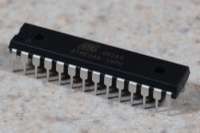
| IC2 | Microcontroller | ATmega8 | Digi-Key | ATMEGA8-16PU-ND | Farnell | 9171380 | 1 | Summary · Full | |
| IC2 | IC Socket | 28 Pin | Digi-Key | ED90038-ND | Farnell | 1103850 | 1 | Data Sheet | |
| J1 | SIO Connector | See SIO Connectors | 1 | ||||||
| J1 (Alt) | DB15 Female Connector | Tyco 5747845-3 | Digi-Key | A32120-ND | 1 | Drawing · Data Sheet | |||
| J2 (Opt) | DB25 Female Connector | FCI D25S24A4GV00LF | Digi-Key | 609-1509-ND | Farnell | 1103915 | 1 | Data Sheet | |
| J3 (Opt) | .100" 12 Position Straight Header | Molex 90131-0126 | Digi-Key | WM8124-ND | Farnell | 1248127 | 1 | Data Sheet | |
| J3 (Opt) | Jumpers / Shunts | AMP 881545-2 | Digi-Key | A26242-ND | Farnell | 4218176 | 5 | Data Sheet | |
| LED1 | Green | Lumex SSF-LXH103GD | Digi-Key | 67-1236-ND | Farnell | 7604762 | 1 | Data Sheet | |
| LED2 | Red | Lumex SSF-LXH103ID | Digi-Key | 67-1235-ND | Farnell | 1382954 | 1 | Data Sheet | |
| LED3-6 | Yellow | Lumex SSF-LXH103YD | Digi-Key | 67-1237-ND | Farnell | 7604804 | 4 | Data Sheet | |
| Q1 | HC-49US Crystal | 14.31818 MHz | Digi-Key | X444-ND | Farnell | 1078917 | 1 | Data Sheet | |
| Q1 (Opt) | Crystal Insulator (Clear) | HC-49/U | Digi-Key | 492-1039-ND | Farnell | 4695471 | 1 | Data Sheet | |
| R1-R6 | Resistor | 150Ω | Digi-Key | 150QBK-ND | Farnell | 1083162 | 6 | Data Sheet | |
| R7 | Resistor | 47KΩ | Digi-Key | 47KQBK-ND | Farnell | 9339558 | 1 | Data Sheet | |
| R8-R10 | Resistor | 3.3KΩ | Digi-Key | 3.3KQBK-ND | Farnell | 9339426 | 3 | Data Sheet | |
| R11-R13 | Resistor | 1.8KΩ | Digi-Key | 1.8KQBK-ND | Farnell | 9341439 | 3 | Data Sheet | |
| R14-R17 (Opt) | Resistor | 330Ω | Digi-Key | 330QBK-ND | Farnell | 9339418 | 4 | Data Sheet | |
| SD1 | SD Card Connector | HEC DM1AA-SF-PEJ(21) | Digi-Key | HR845CT-ND | RS Electronics | 502-5004 | 1 | Data Sheet | |
| SW1-SW4 | Tactile Switch (Right Angle) | Omron B3F-3150 | Digi-Key | SW409-ND | Farnell | 959716 | 4 | Data Sheet | |
| SW1-SW3 (Keycaps) | Black Keycaps | Omron B32-1010 | Digi-Key | SW451-ND | Farnell | 1499312 | 4 | Data Sheet | |
| SW4 (Keycap) | Red Keycap | Omron B32-1080 | Digi-Key | SW252-ND | Farnell | 1436532 | 1 | Data Sheet | |
| SW5 | DIP Switches (3 Pos) | Grayhill 76PSB03ST | Digi-Key | GH7133-ND | Farnell | 1521999 | 1 | Data Sheet | |
| SW6 | Toggle Switch | NKK G12AV-RO | Digi-Key | 360-1759-ND | Farnell | 1288418 | 1 | Data Sheet | |
| Enclosure | Hammond Mfg. 1455L1201BK | Mouser | 546-1455L1201BK | Farnell | 9287841 | 1 | Data Sheet | ||
| End Panels | See End Panels | 1 Set |
In order to make part ordering easier, a number of electronics suppliers allow lists of parts to be imported. The following text files may be used to make ordering easier:
- Digi-Key: digikey_parts_import.txt - All parts, except for enclosure and SIO connector, with black and red keycaps.
- Farnell: farnell_parts_import.txt - Contributed by spookt. All parts except for enclosure, SD slot, SIO connector, and optional DB15 connector.
Finding SIO Connectors
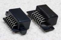
So that one's SDrive NUXX may be as easy to use as possible, an SIO connector footprint has been placed on the PCB. Unfortunately, these connectors are not particularly easy to come by without desoldering one from an old piece of Atari hardware. In my experience I have found there are generally two types of SIO connectors, which can both be see in this photo:
- Thick / Narrow: This connector is immediately identifiable by thick mounting wings protruding from the sides of the connector and raised JAE D03 lettering inside the headshell. I prefer these connectors because their thick mounting wings allow self-tapping screws to be used for holding the connector to the PCB. I've found these connectors in Japanese-made Atari 1010 cassette drives and 1050 printers, and an Okidata printer. (Left in this photo.)
- Thin / Wide: This connector has a much flatter base and slightly longer headshell. Due to the thin base these connectors cannot be used with self-tapping screws and require a nut/bolt/washer or rivet set to attach them to the PCB. (Right in this photo.)
Best Electronics, the gigantic Atari parts supplier, is selling brand new Thin / Wide SIO connectors for US$4.95/ea. These are the exact connectors which are used on the small production run. It is also possible to repair shops which have pulled connectors available, such as B & C ComputerVisions who offers part number PRA015 which is listed as CONN 13 PIN I/0 8-BIT PCB. When I ordered two of these connectors I received two of the Thin / Wide parts. Note that B & C ComputerVisions often has a long lead time as they seem to pull the connectors on an as-needed basis.
Just as a reminder, if you are going to salvage an SIO connector from a piece of hardware, please be sure the hardware isn't worth saving before trashing it just for the connectors.
Design Documents
Please see the license section of this document regarding licensing of these files.
Schematic
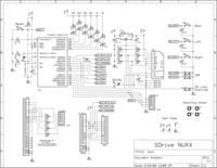
The SDrive NUXX schematic (v1.1) may be obtained from here in PDF format or here as a 300dpi PNG.
PCB Layout
The PCB layout files, consisting of a schematic (.sch) and board file (.brd) were created in CadSoft EAGLE and are available here: sdrive_nuxx_eagle_v1.1.zip (MD5: 56b853336868161a0afc86a572e06661)
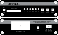
Front and Rear Panels
The front and rear panel artwork, as sent for manufacturing, is available here in Adobe Illustrator format. Note that these files may also be opened with Adobe Reader: sdrive_nuxx_panels_1_0.zip (MD5: 70494f8a2ba25321a9569b8658563d7e)
SIO Connector
The CadSoft EAGLE footprint for the SIO connector is available here: atari_sio_part_for_cadsoft_eagle.zip (MD5: 07f05698e09360178f48f7b06ecd2f86)

License
The schematics (PDF, PNG, and EAGLE formats), PCB layouts (EAGLE and Photoplotter / Drill formats), SIO connector footprint (EAGLE library), and front and rear panel artwork (in PDF, AI, and PNG, and formats) for the SDrive NUXX, which have been created by Steve Vigneau and presented here are made available under Creative Commons Attribution 3.0 United States License. If said files are reused, in accordance with the Attribution requirement of the license, the work may attributed to Steve Vigneau, c0nsumer, and/or nuxx.net.
Any files or content referenced by, linked to, or included on this site which were released by by C.P.U. (Robert Petružela / Bob!k and Radek Štěrba / Raster) remain under their original license.
All other content on this page, including but not limited to copy, photographs, images, etc. remains under its original copyright. If there are any questions about this licensing, please don't hesitate to email Steve Vigneau / c0nsumer and ask.
Sales
For a period of time during 2009-2010 SDrive NUXX PCB and end panel sets, kits, and assembled devices were made available for sale but sold out quickly. Additional assembled devices and PCB / end panel sets are being assembled and will be made available for sale around August 2011.