Millett Hybrid Maxed
Overview
At the beginning of June I happened to read a posting at the MAKE: Blog regarding a tube-based headphone amp called the Millett Hybrid Maxed (or Millet MAX or just MAX). This headphone amp was designed to run from lower voltage tubes thereby not requiring a high-voltage power supply. Best of all, there was a group buy in progress for purchasing PCBs allowing Millett Hybrid Maxes to be fairly easily built.
This updated version of Pete Millett's now classic Low-voltage Hybrid Headphone Amp has some really great features, including a partial version of Ti Kan's relay-based ε12 headphone muting / protection circuit, rectifying power supply, an option for either BJT or MOSFET diamond buffer output stages, and a board designed to fit in the Hammond 1455T1601 enclosure.
After following a few links and finding contact info for the board designer, Colin Toole (cetoole) I emailed him and asked to be a part of the group buy. I eventually purchased five blank PCBs, sending two of them and associated parts off to matt303, who I know from the #llamasoft IRC channel.
More history of the development of the Millett Hybrid Maxed is available here at the MAX website.
Photos from my assembly of the Millett Hybrid Maxed can be found here in my photo gallery.
Tubes
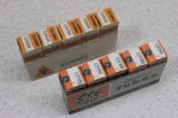
Immediately after securing purchase of the Millett Hybrid Maxed PCBs I began looking around for tubes for the boards. Per the MAX Tubes section of the MAX website there are a number of different tubes available which will work in the MAX. I set to work looking for some, and eventually ended up purchasing two sleeves (of five tubes each) of 12FM6 and 12AE6A parts.
The 12FM6 parts (datasheet) are NOS (new, old stock) GE parts which were purchased via eBay auction 140128067681 for US$4.10/each, shipped. The 12AE6A parts (datasheet) are NOS Teletronics-branded GE tubes for about purchased via eBay auction 250129176268 for $5.83/each, shipped.
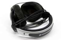
With the 12FM6 parts having a gain of 14 and the 12AE6A parts having a gain of 10, I've selected the 12AE6A parts to be used along with my Sennheiser HD570 headphones. This is currently a good pair, but should I acquire new headphones sometime down the line I may switch to the higher gain tubes.
In order to allow the tubes to mount to the board 7 pin PC mount ceramic tube sockets were purchased from TubeDepot for US$1.99/each. A big draw for many individuals building the Millett Hybrid Maxed is LEDs fitted beneath the tubes so that the tubes are illuminated with a nice, colored glow when the power is turned on. As noted on the Tube Lights page fitting these LEDs requires hollowing out the center of the tube socket.
Since I was initially going to illuminate the tubes in my MAX I went ahead and drilled out the centers of the sockets. I found this could easily be accomplished by fitting the socket in a drill press vise and using a 3/16" bit at 1390 RPM to start drilling into the rivet on the top of the socket. Within a few millimeters of drilling the top of the rivet would separate from the body and the bottom of the rivet would fall out. As the rivet holds the two halves of the socket together, the socket then fell into two pieces. I used standard 15 minute epoxy to stick the two halves back together, taking care not to get any epoxy on the pins.
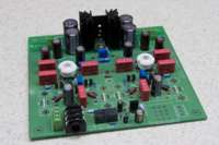
PCB
Assembling the Millett Hybrid Maxed was pretty straightforward and didn't present very many difficulties. Close attention must be paid to the order in which some parts are fitted (eg: the diodes and capacitors in the bridge rectifier (DR1A-DR1D, CR3A-CR3D) and the parts attached to the output stage heatsinks), but generally normal PCB assembly rules (shortest to tallest parts) worked well.
The heatsinks I selected from Mouser (567-647-15ABP for the power supply and 532-531102B25G for the output stage] for the MAX had to be soldered to the PCB for mechanical support. I had no problems soldering these heatsinks with my Weller WES51 and an ETA tip set to 850°F.
Everything on my MAX PCB was soldered using Kester lead-free (Sn96.5/Ag3.0/Cu0.5) solder with a 331 water-soluble flux core. Additional water-soluable flux was added from a Kester 2331-ZX pen as needed.
Boutique Parts
During the assembly of custom amplifiers it is quite common for builders to use particular or favorite (boutique) parts in order to get a very particular sound. One of the most common boutique parts to be used are capacitors. A number of different boutique capacitors are available, with some names such as Elna RFS Silmic, Orange Drops, and Nichicon Muse ES being fairly popular.
I personally built my Millett Hybrid Maxed with what seem to be the more typical / standard Nichion UPW electrolytic and WIMA MKP 10 polypropylene film capacitors.
At some point in the future I may investigate some boutique capacitors, but at this point I'm quite happy with the sound, so I'll probably stay with what is currently there.
Transistor Matching
I am of the opinion that one of the most important things in a headphone amplifier is to have both channels as identical as possible. While the sound coming from the amp can be slightly colored, if there is a noticeable difference between what your two ears hear, it'll likely seem very off balance.
In order to avoid this I made sure to purchase far more of the 2N5087 and 2N5088 transistors than I needed. I ended up using parts 512-2N5087_J18Z and 512-2N5088TA from Mouser in my Millett Hybrid Maxed, and purchasing 100 each of these transistors cost just under US$11. I figured that this wasn't a bad price, especially if it would help ensure that both my friend and I would have headphone amps which are as balanced as possible.
Testing of the transistors was done using an exceedingly cheap CEN-TECH branded DMM from Harbor Freight which just happens to have a built-in hFE meter. Even though the CEN-TECH meter is more accurate than I expected, I still don't trust it to provide an accurate reading of the actual hFE. However, it should be accurate enough to establish relatively closely matched groupings of transistors.
To match the transistors I test them one at a time, noting the hFE, then either writing that value on a piece of paper and placing the transistor next to it, or adding it to a pile of other parts with the same value. After building small piles of similarly-valued parts I will re-test those groups to find pairs (or quads) which are as closely matched as possible.
Using this method I was able to get identical-metering pairs for the complimentary sides, so that parts such as QB4L and QB4R (complimentary parts on different channels) had the same value. I was also able to get matched quads of 2N5087 parts for the constant current supply (CCS -- QA1L/R and QA2L/R) as is recommended under the Matching Transistors section of the MAX Construction page.
Volume Potentiometer Ground
After first assembling my Millett Hybrid Maxed and connecting headphones, I disconnected the input and turned the volume up all the way, just to see how much background noise there was. While noise heard was very minimal, I found that there was a slight popping sound every time I'd touch the knob on the volume pot. Because the chassis and front panel of my MAX is isolated from ground, I figured that this was a grounding issue.
Reading a bit of the Head-Fi Forums confirmed this, and the (what I thought to be) oddly placed GND pad right behind the volume pot position suddenly had a purpose. I ran a small wire from one of the screws on the back of the ALPS volume pot to the GND pad and thereby resolved the problem.
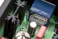
MOSFET Mounting
In order to mount the MOSFETs to the heatsinks I used Mouser Part Number 532-4880SG: Thermalsil™ III Mounting Kit for TO-220, which includes thermally conductive insulating film, a shoulder washer, flat washer, locking washer, 4-40 nut and 4-40 machine screws. Due to the close proximity of the QB9L / QB9R heatsinks in the center of the Millett Hybrid Maxed PCB are slightly too long and will touch in the center of the board. While the screws are isolated by the Thermalsil and shoulder washers, it may be desirable to use shorter screws. I ended up removing the screws provided with the mounting kits and instead using some shorter 4-40 machine screws acquired from the parts bins at Lowes.
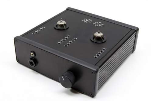
Enclosure
When I first started planning on building the Millett Hybrid Maxed I had planned on constructing a nice wooden enclosure with a metal bottom and metal screen top. However, as time progressed I decided that it would be best to use the same Hammond 1455T1601 enclosure that Tom Blanchard (tomb) had used. I was already experienced with this enclosure, having used it in the MIDIbox SID-NUXX, and it's one that I rather like.
While the PCB was soldered using only RoHS-compliant lead-free solder, I ended up using lead-bearing (Sn63Pb37) Kester solder with a 245 no-clean flux core to solder wired connections to the front and rear panel.
Jacks
To supply feed power into the enclosure I used Mouser part 163-4302-EX, which is a Kobiconn 2.1mm panel mount power jack. This jack mounts cleanly in a 1/2" hole, fastens securely to the panel, and looks good on the panel.
For feeding audio into the Millett Hybrid Max I purchased three parts from Digi-Key, SC1319-ND, SC1144-ND, and SC1145-ND. These three parts fit together to make a panel mount RCA (phono) jack which is electrically isolated from the surrounding panel. They are nickel-plated parts and thusly not always considered optical for audio connections, but they make a solid electrical connection and seem to work well. I may replace them in the future if I can find gold-plated connectors that I like.
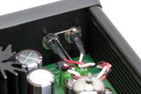
The MAX is normally fitted with a simple Neutrik 1/4" TRS stereo jack for connecting headphones. While most individuals use the silver-faced jack, I ended up using Mouser part 550-20301, the Neutrik NMJ6HFD2, which is a nice, plain, all-black switched connector.
I also installed 161-073SP-EX, a Kobiconn snap-in panel mount 1/8" (3.5mm) stereo headphone jack above the Neutrik so that I can more easily connect headphones with a smaller plug. The wires leading from the 161-073SP-EX connect to a set of screw terminals on the PCB next to the Neutrik jack. Because of the switching mechanism in the 1/4" TRS jack it is only possible to use one plug at a time. This jack snaps solidly into a 3/8" hole drilled in one of the end panels from the Hammond 1455T1601 and has a nice, smooth, finished look with gold contacts.
Knob
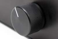
For the front panel I selected a .925" matte black knurled metal knob from Digi-Key, part number 226-4095-ND. This knob is from the same line as I used on the x0xb0x, except one size larger. I really like the look and feel of this knob, and it fits well with the black face of the enclosure.
In order to have this knob fit nicely against the front panel I had to cut down the shaft of the potentiometer. When cutting the shafts of pots it is very important to hold the shaft of the pot while cutting it and not the body. This ensures that no unnecessary (and potentially damaging) sideways force is put on the pot.
To cut this pot I simply measured how much to cut off by fitting the pot through the panel, mounting the knob, and measuring the size of the gap between the pot and the panel. Cut this amount off of the pot shaft and there will be just enough play in the fitting of the knob to seat it just above the panel.
I cut the shaft of the ALPS RK27112A by marking it with a pencil using the method described above, putting the end of the shaft in a vise, and then cutting the shaft with a hacksaw. The shaft felt like some manner of relatively soft aluminum, because it was fairly easy to cut. I then filed the end to remove any burs and soldered the pot into the board.
Power Switch
When I placed the first Mouser order for parts I ordered one of the recommended power switches, 103-R13-135A-02-EV, a large, plain, black round rocker switch. I'm quite happy with this switch. It fit nicely into the enclosure, and the only problem I had with it was drilling a hole large enough to accommodate it. The required hole was .768" in diameter, so I drilled a number of small holes, cut between them, and filed the hole until it was large enough.
Top and End Plates
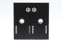
Again following with the described enclosure on the Millett Hybrid Maxed site I mostly reused the drilling templates originally created by Tom Blanchard (tomb), with a few slight modifications. Because I had to mount the PCB for my MAX in the bottom slot of the enclosure I took Tom's end panel templates from here, opened them in Adobe Illustrator, and moved the markings for the hole drill centers and PCB down until the PCB fit in the bottom slot. I also moved the holes for the line-in jacks as I did not care for the original vertical orientation.
The reference design had fitted banana jacks in the back of the MAX for easy metering during biasing, but as I had moved the PCB down slightly (and wasn't interested in mounting them) I didn't drill these holes. I also did not drill the hole for either the front panel LED or the top-panel holes for adjusting the bias trimmers. These exclusions were because I didn't feel a need for power-on indication, and I consider my now-completed MAX to be a stable, completed device which I won't be tweaking / trying in different configurations.
Since I liked Tom's design with a hexagon layout of the power supply vent holes and the rows of vent holes for the MOSFET heatsinks, I used this template as provided.
The resulting templates were printed out and rubber cemented to the front and top panels, center marks to help eliminate drill bit wobble were punched, and then the panels were drilled. Because of the size of the holes for the tubes and the power switch I had to drill a series of smaller holes around the perimeter of the larger hole, cut between the small holes, then file the holes to size.
One inch plastic bushings designed to fit into a 3/4" hole were purchased from Mouser 561-MP10012 and placed in the tube holes, and then epoxied into place. These bushings provided a nicely finished look to the tube holes.
In order to provide a clean, consistent look to the drilled vent holes I filed the top edge of each gently with a round file, producing a slight visible aluminum-colored bevel. I find that this provides a nice visual connection with the silver-colored tops of the 12AE6A tubes.
Voltage / Bias
In setting up the Millett Hybrid Maxed for the first time it is important to set up the main voltage (V+), tube bias, and DB (in my case MOSFET) bias. After I found out about the trimmer orientation issue I set RR3, for adjusting the voltage to the main board to its lowest settings, the tube bias to the middle, and the MOSFET bias to its lowest setting. That is, if the trimmers have been placed according to the silkscreen on the PCB, fully clockwise for RR3, RB12L, and RB12R. The trimmers for RA1L and RA1R should be turned completely to one end, then back about 10 turns (for 20-turn trimmers).
After completing these steps I then set V+ to 27VDC, the tube bias to 13.5VDC, and the MOSFET bias to 200.0mV
These values take a while to stabilize, so I left the MAX powered on for three or four hours at a time with audio playing through it, occasionally disconnecting the audio and headphones and rechecking all these settings. After two days the values stabilized and I felt comfortable closing up the case.
Sound Quality
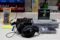
I do not consider myself to be an audiophile, but I do prefer to have good quality sound when it comes to music. Thus far I've been quite happy with the Millett Hybrid Maxed, especially when coupled with a line-out signal from an iPod (via its dock connector) and Apple Lossless audio files. I have also had decent luck using a Sony Playstation (SCPH-1001) as a CD player. It has great grassroots support as an excellent CD player and DAC, but I have yet to determine just how much I like using it.
Using my Sennheiser HD570 headphones with the Millett Hybrid Maxed has proven to been a very pleasant experience, hearing detail in music which I hadn't really heard before with other headphone amps.
Operating Temperature
As indicated by the drilled vent holes and large heatsinks, the design of the Millett Hybrid Maxed requires a fair bit of cooling. While running the amp feels warm to the touch, but not particularly hot. One day while at work I decided to use both my Fluke 179 and a thermocouple and a cheap infra-red thermometer to determine approximately how hot things were running. The MAX has been biased as described and was running with an iPod feeding it audio and approximately 1/3 volume (my typical listening conditions).
I suspect that the infrared thermometer is slightly off, although I have not yet determined how inaccurate. I believe this inaccuracy is because infrared thermometers require calibration based on the surface being metered, as different surfaces dissipate infrared differently.
With the ambient temperature of the room being 73.4°F (23°C) I powered on the MAX. After running for around two hours, the following temperatures were measured with the thermocouple:
- Power Supply Heatsink: 142.5°F (61.4°C)
- QB8L Heatsink: 130.4°F (54.7°C)
- QB9L Heatsink: 141.0°F (60.6°C)
- QB8R Heatsink: 128.9°F (53.8°C)
- QB9R Heatsink: 143.4°F (61.9°C)
- Ambient chassis air, approximately between tubes: 125.5°F (51.9°C)
The following temperatures were measured with the infrared thermometer:
- Center of top chassis, between tubes: 100.7°F (38.2°C)
- Between power supply heatsink vents: 109.5°F (43.1°C)
- Between QB9L and QB9R heatsink vents: 100.2°F (37.9°C)
Power Consumption
With my MOSFET output stage Millett Hybrid Maxed biased as described I connected it to a Sony Playstation (SCPH-1001) and took a number of current readings between the wall wart power supply and the MAX. During all of these readings the Playstation was playing an audio CD and the volume pot was set to approximately 1/3. These readings matched those taken when troubleshooting the inrush current problem:
- Maximum Inrush, Power On When Cold: 1.796A
- Maximum Inrush, Power On When Warm: 1.521A
- Cold Steady State: 693mA
- Warm Steady State: 647mA
Note that the steady state current draw seemed to occasionally decrease by 1mA even once the amp was warm, with this decrease happening less frequently the longer the MAX was on.
Issues
Here are three issues I encountered during my assembly of the Millett Hybrid Maxed. After a fair amount of discussion at both the DIYForums.org Forum and the Head-Fi Forums I found that some other individuals have encountered some of these problems as well, so I am fairly confidant they are not unique to my PCB set or parts selection. Issues identified here are not considered by everyone to be problems, with some people even believing that installing fuses on the PCB leads to more problems than it can resolve. However, I am of the opinion that these issues identified here are worth noting and working with / around during assembly of the Millett Hybrid Maxed.
Trimmer Orientation
The design of the Millett Hybrid Max has the trimmers oriented in a somewhat confusing manner. If the trimmers are oriented as the silksceen indicates, trimmers RR3, RB12L, and RB12R set their respective adjustments (V+ and MOSFET bias) to the lowest possible value by being turned completely clockwise.
The trimmers RA1L and RA1R for the tube bias need to be turned completely couter-clockwise (anti-clockwise) in order for the tube bias to be at its lowest possible values.
Due to confusion over this I ran into a problem where I could only meter ~2.6VDC between V+ and GND after first assembling my Millett Hybrid Maxed. No matter how I turned RR3 I could not get the output voltage to change. After a friend happened across a message board posting discussing the trimmer orientation issue I was able to properly set up the board. I suspect that inadvertently having the MOSFET bias trimmers turned all the way up (I had set them full counter-clockwise) was causing the MOSFETs to sink more current than the power supply could provide.
In order to fit all trimmers so that when they are turned fully counter-clockwise (the typical position for lowest value) RR3, RB12L, and RB12R should be installed opposite the position indicated by on-board silkscreen.
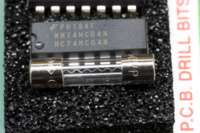
Power Supply and Fuses
According to the official BOMs posted prior to 21-August-2007 the recommendation was for a 1A power supply and 1A fuse. When ordering parts for my Millett Hybrid Maxed I followed these guidelines, selecting the Jameco 24VAC 1A power supply and Digi-Key Part 283-2678-ND, a 1A 250V fuse, but ran into problems. After getting my MAX up and running for a few days it suddenly began blowing fuses. I poured over the schematic for hours, removed a couple of components, and even replaced the MOSFETs before identifying the actual problem: unexpectedly high inrush current.
After watching a number of straight-wire fuses burn out in a short but bright flash and running out of ideas as to what could be wrong, I decided to connect a multimeter in series with the AC jack and measure how much current the Millett Hybrid Maxed draws as it blows its fuse. After inserting a new style of fuse (Mouser PN: 576-0217001.HXP) and connecting the meter, I stared at the fuse while flipping the power switch. To my surprise I saw the kinked wire in the fuse twitch, but not break. Looking over at the meter I saw that while the amp was running at a steady current of around 300mA (with the MOSFETs turned all the way down) it had peaked at 1.758A during power-on. That's almost 2x what the fuse and power supply are rated for.
I am currently using the 1A power supply and 576-0217001.HXP 1A kinked wire fuse in my Millett Hybrid Maxed, but I don't feel that this is appropriate with such a high inrush current. Knowing that the wire in the fuse is physically deforming and almost breaking with each power on makes me wonder if the amp will actually work each time I power it on.
I see two potential solutions to this issue. The one which I will try first, and which may be acceptable, is to use a slow-blow 1A fuse which shouldn't be as sensitive to the split-second high inrush current. As it is matched with the power supply and provides plenty of headroom for the normal current draw of the MAX it should be acceptable. However, the high inrush still risks damaging the power supply.
A more proper solution would be to replace the power supply and fuse with 2A parts, ensuring that the inrush current is well within the tolerances ranges the power supply and fuses are designed for. It is likely that other designs with hand-selected (boutique) capacitors, a different output stage, and other component changes will have a different inrush current and thereby different maximum power requirements.
Please note that as of 21-Aug-2007 the Official BOM has been updated to recommend the 1A fuse as a starting point only.
Groundplane
When mounted in a Hammond 1455T1601 enclosure the Millet Hybrid Maxed PCB is designed to slide cleanly into the grooves in the sides of the enclosure. While this works great, due to the groundplane extending fully to the left and right sides of the PCB, there is a risk that the enclosure can rub through the soldermask and make contact with the groundplane.
A short between the case and the groundplane is not any sort of shock risk nor does it pose a problem, but I feel that it is best to take care and ensure that the inserting and removing the board from the case doesn't wear through the soldermask.
External Links
- DIYForums.org - Home of the Millett Hybrid Maxed
- Millett Hybrid Maxed Overview - Main Millett Hybrid Maxed Page
- Head-Fi.org - High-end Headphones and Portable Audio Forum
- HeadWize - Where I first read details of the Millett Hybrid Maxed and the PCB group buy.
- AMB audio shop - Great source of parts for custom amp designs, including some of AMB's (Ti Kan) own.