x0xb0x

About
In early 2006 I built an x0xb0x, which is an open-source clone of the famous Roland TB-303. As the x0xb0x site states:
- The x0xb0x is not just another MIDI-controlled TB-303 clone. x0xb0x is a full reproduction of the original Roland synthesizer, with fully functional sequencer. The sequencer can be programmed just like the original 303 (ok its actually a little easier, we think) and can be used to control other synthesizers via any of its various output formats. 128 banks of track memory and 64 banks of pattern memory are stored in onboard EEPROM, no battery-backup is needed!
Beyond just building the kit, I also made a few changes to make it more of what I wanted.
In June 2007 I acquired a second x0xb0x kit, serial number 496, and assembled it in the same manner as number 231. There are only minor differences between it and #231. Most particularly: I didn't order a lot of 2SA733 transistors and select from them. I simply metered the ones shipped with the kit and ordered them accordingly. R1 in the power supply was not replaced, but R16 was, in order to get MIDI In functioning.
In December 2008 I began building a third x0xb0x kit, serial number 888. This version was built as stock, except with the 2SA733 transistors sorted for best placement, red LED option, rear panel painted black, artwork from AbleIdeas applied to the front panel, and my standard red Run button and new Bank and Mode knobs. This is basically just like #496.
Modifications To Kit
LEDs
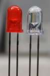
I didn't like the look of the water clear red LEDs which shipped with the x0xb0x kit, so I replaced them with red diffuse LEDs from Digi-Key. These LEDs are part number 67-1105-ND.
The resistors which came with the x0xb0x kit for driving the LEDs were a bit too high of a value. That is, once the new LEDs were installed everything appeared kinda dim, so those were replaced with 820Ω parts.
Noisy Power Supply
The x0xb0x mods page states:
- "the warble in the resonance is due to powerline fluctuations since the synth is run off of an op amp as a power supply. it has troubles at high current draw. also there are tons of low pass filters on the supply that cause droops when large power surges occur. r95 and c28 for example. at any rate, the power supply we built was a bit stiffer than the original. this stiffness can be taken away by increasing the resistance of 100ohm resistor that feeds the opamp. i havent verified this but im pretty sure it would give more warble as the op amp would saturate sooner at higher currents also the bypass cap at that point could be decreased"
In order to make the power supply in #231 a bit more noisy and to hopefully obtain a sound closer to the original TB-303, R1 in the power supply was replaced with a 200Ω part.
R1 in #496 was left with its original 100Ω part.
Power Switch
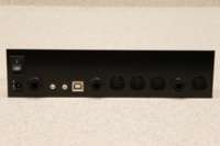
The x0xb0x does not come by default with a power switch, so I salvaged one from an old power supply and installed it in the rear panel. This required cutting one trace and inserting jumpers to the switch.
Rear Panel
The rear panel of the x0xb0x was painted matte black with Krylon Fusion spray paint. I've found that this paint works well on both aluminum and plastic.
Artwork
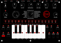
While the original x0xb0x front panel looks nice, it really isn't what I wanted. So, I went ahead and designed some new artwork complete with a new logo for it. I had 12 of these panel overlays printed by Maverick Label, and the extras were sold at cost along with a red Run button to readers of ladyada's tea party, a forum run by the designer of the x0xb0x.
These labels are adhesive-backed rear-printed textured Lexan, making them the same as the panel overlays on many industrial products. Thusly they should stand up to years of abuse.
While the labels were being printed, Maverick Label seems to have run into a few problems with the order. The first set was missing the Bank indicator lines, and the second had the text and cutouts shifted by almost 2mm. Maverick Label was very helpful with each of the errors and worked to correct them immediately. I feel that the issues are mostly related to the complexity of the job, and with Maverick Label's excellent handling of the problems I'll be sure to use them next time I need custom labels printed.
In December 2008 a company called AbleIdeas began selling copies of my x0xb0x artwork after I released it into Creative Commons.
Red Run Button
In order to best fit with the new artwork and balance the look of the board, I used a red keycap for the run button on the front panel. This is Digi-Key part 401-1154-ND.
Bank / Mode Switch Knobs
The knobs on the Bank and Mode switches were replaced with some black aluminum knobs from Digi-Key, part number 226-4090-ND. I don't think they are a perfect match for the board, but they are better than the ones which came with the kit.
Transistors
The x0xb0x mods page also states:
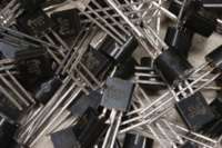
- "the more pronounced resonance of the 303 is due to the high gains on the pnp transistors in the vcf. we couldnt get the exact 'binned' parts so the gains may not be as high as the original. the 2sa733p has a beta (gain) which ranges from 270 to 310 or so whereas the 2sa733ap has a beta from 300 to 350 or something of that nature. (the original used 2sa733ap's whereas we use 2sa733p's) ...so if they check the betas they can place them at the right place. id start with q10 then q9 and if there is one good one left the vco could use one at q8"
When building #231 I picked up a bag of 100 2SA733 transistors from Mouser, which are part number 512-2SA733P. I tested them one by one and sorted out the highest beta parts. For #496 I simply ranked the parts which were shipped with the kit and selected them accordingly.
In the end, I replaced the following transistors with the following value parts:
| Serial Number 231 | ||
|---|---|---|
| Part Name | Value | |
| Q10 | 338 | |
| Q9 | 338 | |
| Q8 | 349 | |
| Q36, Q38 | 335 | |
| Q27 | 337 | |
| Q33 | 331 | |
| Q1, Q2, Q31 | 327 |
| Serial Number 496 | |
|---|---|
| Part Name | Value |
| Q10 | 341 |
| Q9 | 337 |
| Q8 | 329 |
| Q36 | 303 |
| Q38 | 304 |
| Q27 | 309 |
| Q33 | 301 |
| Q1 | 287 |
| Q2 | 286 |
| Q31 | 293 |
| Serial Number 888 | |
|---|---|
| Part Name | Value |
| Q10 | 366 |
| Q9 | 346 |
| Q8 | 344 |
| Q36 | 342 |
| Q38 | 342 |
| Q27 | 339 |
| Q33 | 318 |
| Q1 | 307 |
| Q2 | 302 |
| Q31 | 286 |
#496 MIDI
Likely because of some variance in the 4N37 optocouplers and/or 2SC536F transistors used in the MIDI In circuit, R16 had to be replaced with a 120Ω part in #496. With the original 100Ω part the MIDI In signal wasn't being driven hard enough so that the CPU could detect it. The solution for this was posted in the ladyada.net forums which I had read a few days before building #496. Since mine had this problem I gave this fix a try first (after validating all parts were fitted as per the kit directions) and it worked.