Please Note: This project is a work in progress and all information contained within is subject to change. Documentation is currently incomplete and is being written as it is developed.
About
As part of building a headphone amplifier I found myself needing a way to connect multiple audio sources to one enclosure and pick which one is fed to the amplifier. After playing with a number of purely mechanical solutions I decided that pushbutton input selection with some sort of indicator would be ideal. Unable to find an existing open source project for this I decided to make my own and share it. Here it is, the nuxx Audio Input Switch or nAIS.
Features
The nuxx Audio Input Switch has the following features:
- Two to five inputs, selectable via jumpers.
- Next / Previous / Mute Functions.
- Input selection and mute state maintained during power off.
- Discreet LED connectors for indicating current input, power, and mute status.
- Capable of switching balanced or unbalanced audio (common ground).
- Lower cost parts may be used in assembly if switching unbalanced audio is not needed.
- Fail-safe design so two inputs are never connected together.
- Powered from AC, DC, or regulated 5VDC. If AC or DC power sources are used, the 5VDC connector becomes an output for powering other devices.
- Open Source (MIT Licensed Software, Creative Commons Non-Commercial Circuit and Hardware)
Use
The nuxx Audio Input Switch is designed to have up to three buttons connected to J2, exposing the Next, Previous, and Mute functions. The next and previous buttons rotate forward or backwards through the inputs and the currently active input is indicated via LEDs connected to J3. The mute button alternately disconnects all inputs and activates the mute LED or restores the previously used input.
Each time a new input is selected or mute is enabled or disabled, this change is written to the microcontroller's internal EEPROM, saving the state of the device when power is removed. This state (both the current input and the mute setting) is then restored when the switch is powered up the next time.
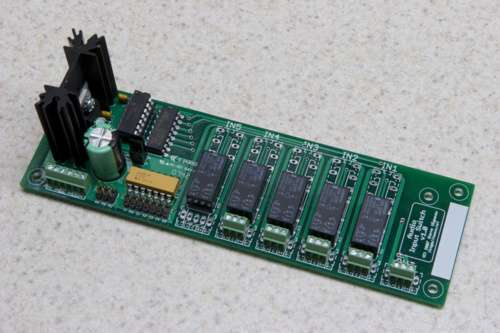
Pinouts / Header Information
J1
Power connections:
- AC IN: AC input to the bridge rectifier, which then feeds the voltage regulator.
- DC IN: DC input to the voltage regulator. (Positive on left, indicated by heavy white line.)
- 5VDC: 5VDC in or out, depending on power configuration. Connects just after voltage regulator. (Positive on left, indicated by heavy white line.)
J2
Switch connections:
- NX: Next Input
- PR: Previous Input
- MU: Mute Toggle
J3
LED connections. Anodes connect to +5V, cathodes connect to discreet pins:
- +5V: Common 5VDC for LED anodes.
- M: Mute: Indicates that Mute function is active.
- PW: Power: Always On
- I1: Input 1
- I2: Input 2
- I3: Input 3
- I4: Input 4
- I5: Input 5
J4
Jumpers for configuring the number of inputs.
IN1 - IN5 / OUT
Audio input / output connectors:
- L-: Left Channel Negative (Balanced Only)
- L+: Left Channel Positive
- C: Common / Ground
- R+: Right Channel Positive
- R-: Right Channel Negative (Balanced Only)
Configuration Choices
Beyond custom designs for front and rear panel connectivity, three major choices must be made when choosing how to assemble one's nuxx Audio Input Switch: number of inputs, type of audio switched, and power source.
Number of Inputs
The number of inputs to be switched is selected by setting jumpers A and B on JP1 according to the following table. Either .100" pin headers and shunts (also known as jumpers; to build a reconfigurable switch) or soldered-in wire jumpers may be fitted may be used to make these selections. Additionally, surface mount jumpers labeled A and B have been provided on the solder side of the PCB. Any combination of these jumpers may be used.
| A (RA4) | B (RA5) | Input Count |
|---|---|---|
| - | - | 2 |
| X | - | 3 |
| - | X | 4 |
| X | X | 5 |
The selected number of inputs selected will then be cycled through while pressing the Next or Previous buttons. It is not necessary to fit input terminals or relays for inputs that will not be used. Note that if a number of inputs selected via J1 is lower than the last input selection saved in the EEPROM, the last saved input selection will be reset to Input 1.
Type of Audio Switched
The nAIS has been designed to switch either balanced or unbalanced audio. When used for unbalanced audio, cheaper DPDT relays and three-pin screw terminals may be used on the board, but when switching balanced audio, 4PDT relays and five-pin screw terminals are required. Of course, if one builds a board for balanced audio, unbalanced can still be switched, but half of each relay will go unused.
Relays and screw terminals an unbalanced configuration (two lines switched):
- Relays: 653-G6A-234P-DC5
- Terminals: 651-1725669
Relays and screw terminals balanced configuration (four lines switched):
- Relays: 653-G6A-474P20-DC5
- Terminals: 651-1725685
Power
There are three choices for power sources in the nAIS: AC, DC, or 5V DC. Assembly using all the parts listed in the BOM will make for a nAIS with all three of the following options usable. If you opt to use DC in or 5V DC in, parts listed in the respective sections may be omitted.
AC: To power the Audio Input Switch from AC, the board must be assembled with all listed components. AC power is fed into the AC connector, passed through a rectifier (B1), then regulated down to 5V by IC3 to provide power for the microcontroller, driver, relays, and LEDs. AC input for the board has been tested at 6.2VAC - 24VAC. Be warned that the higher the voltage supplied the more heat will be dissipated by IC3 via the heatsink. When powering the board from AC power in this manner the 5V DC terminal may be used as a simple power supply for other devices.
DC: The Audio Input Switch can be powered with anything from 7VDC to an (absolute maximum) of 35VDC fed into the DC IN connector. The positive terminal is the left side, indicated by the heavy white line. This power is then regulated down to 5V by IC3 and used to power the microcontroller, driver, relays, and LEDs. Because the rectifier B1 is not needed, it may be left out when powering the board from DC. Be warned that the higher the voltage supplied the more heat will be dissipated by IC3 via the heatsink. When powering the board from DC power in this manner the 5V DC terminal may be used as a simple power supply for other devices.
5V DC: It is also possible to bypass the Audio Input Switch's power supply entirely and power the board directly from 5VDC. This is done by feeding 5VDC to the 5V DC connector. The positive terminal is on the left side, indicated by the heavy white line. When powering the board directly from 5VDC parts B1, C1, IC3, and the heatsink are not needed and may be omitted.
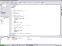
Firmware
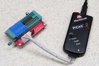
The firmware for the nuxx Audio Input Switch was written in mikroElektronika's mikroBasic. This language allowed me to complete the firmware in just a few hours, easily testing it on one of mikroElektronika's EasyPIC4 development boards. This firmware can be programmed into the microcontroller via any standard PIC programmer which supports the PIC16F630, such as the low cost PICkit 2. For programming PICs after development I use a PICkit 2 connected to a ZIF socket via a custom cable.
License
The firmware for the nuxx Audio Input Switch is released under the MIT License so that anyone can use it freely. While I don't require it, if you do use the firmware in one of your projects (be it commercial or otherwise) I'd appreciate it if you would let me know.
Files
The firmware for the nuxx Audio Input Switch is currently at v1.0-RC, the release candidate for v1.0. It will be incremented to v1.0 once it has been tested on production hardware and any remaining issues are found and sorted out. The software is available here:
- Binary: nuxx_audio_input_switch_firmware_1_0-RC.hex (MD5: 9720b40205922e8dc8b1929df1e9119c)
- Project File and Source: nuxx_audio_input_switch_firmware_1_0-RC_source.zip (MD5: 11b91990f0ea7b964d9beadeeaec5982)
- Plaintext Source for Reading: nuxx_audio_input_switch_firmware_1_0-RC.pbas.txt (MD5: 1146e76d50109755a5ca26cbccc8dee8)
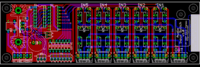
Hardware
The nuxx Audio Input Switch's was designed in CadSoft EAGLE. I used this for drawing the schematic of my initial idea, laying out the PCB, and generating the photoplotter and drill files for manufacturing.
Files
As mentioned below, these files fall under the Creative Commons Attribution-Noncommercial 3.0 license.
- Schematic: nuxx_audio_input_switch_1_0_schematic.pdf (MD5: d6a96e8661281f466eabc691b8c06ae1)
- EAGLE Files (.brd and .sch): NOT YET (MD5:)
- Photoplotter and Drill Files (Gerber RS-274X and Excellon): NOT YET (MD5:)
License
The schematic and PCB files for the nuxx Audio Input Switch are released under the Creative Commons Attribution-Noncommercial 3.0 license. While I would have liked to release the designs under a less restrictive license, the PCBs were designed with a CadSoft EAGLE Non-Profit License, dictating that devices designed with it are not sold commercially. This includes, but is not limited to, any sort of for-profit group buy and eBay sales.
If you have questions about the licensing of this hardware design or wish to pursue alternate licensing, please email me: c0nsumer@nuxx.net.
Of course, as the firmware is freely available you are free to wholly reimplement my design with that software.
Bill of Materials
This list contains a listing of all the parts (and potential alternatives) for assembly of the nuxx Audio Input Switch:
| Part Name on PCB | Value | Mouser Part Number | Quantity | Photo | Catalog Description |
|---|---|---|---|---|---|
| B1 | DF01M | 512-DF01M | 1 | Fairchild Semiconductor: Rectifiers - Bridge 1.5A Bridge | |
| C1 | 1000μF | 140-HTRL35V1000-RC | 1 | Xicon: Hi-Temp Radial Electrolytic Capacitors 35V 1000uF 105C | |
| C2,C4 | .1μF | 581-SR205E104MAR | 2 | AVX: Radial Monolithic Capacitors SR20 0.1uF 50volts Z5U 20% | |
| C3 | 10uF | 140-HTRL25V10-RC | 1 | Xicon: Hi-Temp Radial Electrolytic Capacitors 25V 10uF 105C | |
| IC1 | PIC16F630 | 579-PIC16F630-I/P | 1 | Microchip: PICmicro - PIC16Fxxx Flash MCUs 1.75KB 64 RAM 12 I/O | |
| IC1-SOCKET | DIP14 | 575-193314 | 1 | Mill-Max: DIP Low Profile Sockets 14P TIN PIN GLD CONT | |
| IC2 | ULQ2003A | 511-ULQ2003A | 1 | STMicroelectronics: Darlington Arrays Seven NPN Array | |
| IC3 | LM7805 | 511-L7805ACV | 1 | STMicroelectronics: Voltage Regulators 5.0V 1.0A Positive | |
| IN1-IN5, OUT | 5-pos MPT | 651-1725685 | 5 | Phoenix Contact: PCB Terminal Blocks 5P 2.54mm 90DEG | |
| IN1-IN5, OUT (Alt) | 3-pos MPT | 651-1725669 | 5 | Phoenix Contact: PCB Terminal Blocks 3P 2.54mm 90DEG | |
| J1 (Optional) | 4 Place (2x2) Header | 571-1032402 | 1 | Tyco Electronics / AMP: AMPMODU Breakaway Headers 4P HEADER GOLD 30u, double row | |
| Jumpers (Optional) | 517-953-30 | 2 | 3M Electronic Solutions Division: .100" Pin Strip Headers .100 SHUNT GRAY | ||
| J2 | 6 Place (2x3) Header | 571-1032403 | 2 | Tyco Electronics / AMP: AMPMODU Breakaway Headers 6P HEADER GOLD 30u, double row | |
| J3 | 14 Place (2x7) Header | 571-1032407 | 1 | Tyco Electronics / AMP: AMPMODU Breakaway Headers 14P HEADER GOLD 30u, double row | |
| J4 | 6-pos MPT | 651-1725698 | 1 | Phoenix Contact: PCB Terminal Blocks 6P 2.54mm 90DEG | |
| K1-K5 | 4PDT | 653-G6A-474P20-DC5 | 5 | Omron Electronics: Relays - Low-Signal HI SENS 4PDT 5VDC Non-latching | |
| K1-K5 (Alt) | DPDT | 653-G6A-234P-DC5 | 5 | Omron Electronics: Low Signal Relays - PCB 1 AMP 5VDC DPDT SEALED | |
| HEATSINK | 1.5" Heatsink | 532-531102B25G | 1 | Aavid: Heatsink TO-220, VERT 10.4 TR | |
| HEATSINK (Alt) | 1" Heatsink | 532-531002B25G | 1 | Aavid: Heatsink TO-220, VERT 13.4 TR | |
| Heatsink Mounting | 532-4880SG | 1 | Aavid: Heatsink Hardware MOUNTING KIT TO-220 | ||
| PCB | 1 | Link to group buy... | |||
| RN1 | 180Ω Resistor Network | 652-4114R-1LF-180 | 1 | Bourns: DIP Thick Film Resistor Networks-Leadfree 14pin 180ohms Isolated Low Profile | |
| R1-R7 (Alt) | 150Ω Resistor | 271-150-RC | 7 | Xicon: 1/4W 1% Metal Film Resistors 150ohms 1% 50PPM |
In order to facilitate many different LED configurations, the parts RN1 (a resistor network) and R1 - R7 are fitted into the same footprint. The value of these resistors should be based on the LEDs connected to the device. This LED resistor calculator may come in handy for calculating the value for these resistors.
This list may be pasted into the Mouser BOM Import Tool (requires My Mouser login) to order all of the parts listed above on the BOM. Be sure to delete parts which aren't needed, particularly unneeded relays, screw terminals, resistors, and heatsinks:
512-DF01M 1
140-HTRL35V1000-RC 1
581-SR205E104MAR 2
140-HTRL25V10-RC 1
579-PIC16F630-I/P 1
575-193314 1
511-ULQ2003A 1
511-L7805ACV 1
651-1725685 5
651-1725669 5
571-1032402 1
517-953-30 2
571-1032403 2
571-1032407 1
651-1725698 1
653-G6A-474P20-DC5 5
653-G6A-234P-DC5 5
532-531102B25G 1
532-531002B25G 1
532-4880SG 1
652-4114R-1LF-180 1
271-150-RC 7
Other
This information is just a placeholder for some notes to myself. Ignore these:
- Standard Red Diffused 3mm: 638-204HD (150Ω)
- Standard Green Diffused 3mm: 638-204GD (180Ω)
- Tactile Switches
- 101-0261-EV
- 101-0361-EV
- 101-0461-EV
- Cable
- Scrap
- Connectors
- 6P Connector: 538-22-55-2061
- 14P Connector: 538-22-55-2141
- Pins for 6P & 14P Connector: 538-16-02-0103
- 14P IDC: 517-89114-0001
- 14P IDC Strain Relief: 517-3448-89114