Overview
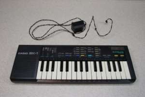
When my sister and I were growing up in the 80s my parents purchased a Casio SK-1 for us. Years later I found myself wanting to trigger the interesting sounds it made (both internally and via it's unique single-patch sampler) via MIDI.
After coming across Paul Messick's SK-1 MIDI Mod which adds MIDI support, I decided that I wanted to build one for myself. After first using an untested PDF layout found on his page and finding it to not work (and missing at least one part from his schematic) I put the project on hold for a while. I'm not certain if the problem was the board I etched or an incorrect board layout which caused the problems I was having, but I stopped work on this project for a few months regardless.
Some photos taken during that first attempt can be found here.
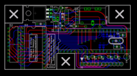
After mostly wrapping up the MIDIbox SID-NUXX I decided to revisit the Casio SK-1 MIDI Mod project and began laying out a new PCB based on Paul's original schematic. It has been designed with low-profile components to fit within the open space in the SK-1. I've also added some bypass caps to help ensure the device's stability.
NOTE: Much of the information found on this page was gleaned from Paul's MaxMidi DYI - SK-1 MIDI Mod page. I am not attempting to plagerize Paul's work, but some of this needs to be duplicated in order to properly document the project.
Abandoned!
This project has been abandoned. After implementing Paul's original design (as detailed in the Overview) with a different optocoupler, things failed to work. At this point I'm not sure where the problem is. I've repeatedly checked my layout against Paul's reference design, and the PCBs match his schematic exactly.
After validating my design I next suspected the EPROMs to be bad. I sent off one of the EPROMs purchased directly from Paul to a friend, and he found that the software it contained did not match what was available for download. The EPROM was then reprogrammed with the downloaded firmware and sent back to me. Still, the design didn't work.
At this point I suspect that over the years something between the original design and Paul's reference schematic became lost. Or that I screwed something up and missed it during repeated reviews. Thusly I've stopped working on this project. If you would like to download the current v1.2 design and see where I may have gone wrong, please feel free. If you do find an error, please mail me and let me know.
If I find time in the future I may attempt to design a new Casio SK-1 MIDI input using Microchip's PIC microcontrollers. This is unlikely to happen for a while, though.
Firmware
The firmware which runs on the Casio SK-1 MIDI Mod was written by Paul Messick and needs to be burned on to a 2732A EPROM in order to be used. A pre-programmed EPROM is available for purchase from him, or else you can download the firmware from Paul's site and burn the EPROM yourself.
Please note that the Creative Commons license which applies to most of this page and my PCB layout does not apply to Paul's software. For licensing information regarding this software, please contact him directly.
Jumper Settings
(Text directly from MaxMidi DIY SK-1 MIDI Mod.)
- The MIDI mod has several modes of operation. By default, the interface will set itself to receive on the first channel that it hears. For example, if the first message that it receives (after being turned on) is on channel 5, from then on it will only respond to MIDI data on channel 5. The interface will forget its receiving channel when power is removed.
- To force the instrument to respond only to a particular channel, connect the "F" jumper and set the address using the "1", "2", "4", and "8" jumpers. See the table below for help.
- The SK-1 can only play four notes at a time. Normally, the MIDI mod will reassign notes on a first-played first-reassigned basis if more than four simultaneous notes are played via the MIDI input. If the "A" option is jumpered, notes after the fourth one will be ignored. This is similar to the way that the SK-1 handles voice assignment using its own keyboard.
- Because it is designed only to work with its internal 31-note keyboard, the SK-1 can only play notes from F2 to C5. The MIDI interface will normally wrap notes that are outside of this range to the nearest playable octave. So, if F1 is played, it will sound the F2 on the instrument. Likewise, C#5 will wrap to C#4. To disable this behavior, connect the "X" option jumper. With "X" selected, out of range notes are simply ignored.
| A | F | 1 | 2 | 4 | 8 | X | Description |
|---|---|---|---|---|---|---|---|
| - | 0 | - | - | - | - | - | Auto MIDI Channel Assignment |
| - | 1 | 0 | 0 | 0 | 0 | - | MIDI Channel 1 |
| - | 1 | 1 | 0 | 0 | 0 | - | MIDI Channel 2 |
| - | 1 | 0 | 1 | 0 | 0 | - | MIDI Channel 3 |
| - | 1 | 1 | 1 | 0 | 0 | - | MIDI Channel 4 |
| - | 1 | 0 | 0 | 1 | 0 | - | MIDI Channel 5 |
| - | 1 | 1 | 0 | 1 | 0 | - | MIDI Channel 6 |
| - | 1 | 0 | 1 | 1 | 0 | - | MIDI Channel 7 |
| - | 1 | 1 | 1 | 1 | 0 | - | MIDI Channel 8 |
| - | 1 | 0 | 0 | 0 | 1 | - | MIDI Channel 9 |
| - | 1 | 1 | 0 | 0 | 1 | - | MIDI Channel 10 |
| - | 1 | 0 | 1 | 0 | 1 | - | MIDI Channel 11 |
| - | 1 | 1 | 1 | 0 | 1 | - | MIDI Channel 12 |
| - | 1 | 0 | 0 | 1 | 1 | - | MIDI Channel 13 |
| - | 1 | 1 | 0 | 1 | 1 | - | MIDI Channel 14 |
| - | 1 | 0 | 1 | 1 | 1 | - | MIDI Channel 15 |
| - | 1 | 1 | 1 | 1 | 1 | - | MIDI Channel 16 |
| 0 | - | - | - | - | - | - | Enable Voice Reassignment |
| 1 | - | - | - | - | - | - | Disable Voice Reassignment |
| - | - | - | - | - | - | 0 | Wrap Out Of Range Notes |
| - | - | - | - | - | - | 1 | Ignore Out Of Range Notes |
Bill Of Materials
PCB
Design
Because PCBs of Paul Messick's SK-1 MIDI Mod were no longer available, I decided to design my own. This was designed in CADsoft EAGLE and is being released under the Creative Commons Attribution-NonCommercial-ShareAlike 2.5 license for use by all.
These files are v1.2, as both v1.1 and 1.0 contained errors. v1.1 is fixable with two small jumpers, but due to a huge mistake I made in reading the original schematic, v1.0 is generally unusable. These v1.0 boards have since been turned into coasters.
Manufacturing
These PCBs were paneled two to a board and sent to PCBEX.com for manufacture. As detailed in my PCB Prototype Shops review of PCBEX.com these boards are quite nice and will likely be my low-quantity prototype PCB supplier for for a while.
Purchasing
Due to the limited availability of ROMs for the boards and the issues with the v1.1 boards, I am not making these available for sale. However, you are more than welcome to etch some yourself or order a run.
Versions
- v1.2 - Correct.
- v1.1 - Optocoupler wired to MIDI input incorrectly. To fix:
- - Lift trace on top of board between R8 and IC5 Pin 3.
- - Lift trace on top of board between IC5 Pin 2 and MIDI_IN Pin 5.
- - Connect open side of R8 to cathode of D1 / IC5 Pin 2.
- - Connect MIDI_IN Pin 5 to IC5 Pin 3.
- v1.0 - Completely broken. Do not use / unavailable.
Components on PCB
| Part Name on PCB | Value | Part Number | Quantity | Catalog Description |
|---|---|---|---|---|
| C1, C2 | 100nF | 80-C412C104K5R | 2 | Kemet Conformally Coated Axial Ceramic Capacitors 50V X7R .1uF 10% |
| C3, C4 | 10uF | 140-L16V10-RC | 2 | Xicon Ultra Miniature Radial Electrolytic Capacitors 4X5mm 16V 10 |
| C5, C6 | 27pF | 81-RPE5CA270J2P1Z03B | 2 | Murata Monolithic Radial Lead Capacitors 27pF 100volts COG |
| D1 | 1N4148 | 512-1N4148 | 1 | Fairchild Semiconductor Small Signal Diode 100V Io/200mA BULK |
| IC1 | LM7805 | 511-L7805ACV | 1 | STMicroelectronics Voltage Regulators 5.0V 1.0A Positive |
| IC2 | 74LS373 | 595-SN74LS373N | 1 | Texas Instruments Logic - Flip-Flops, Latches, and Registers DIP-20 Octal D-Type |
| IC3 | 2732A | 1 | EPROM programmed with MaxMidi DIY - SK-1 MIDI Mod firmware. | |
| IC4 | 80C31 | 809495-ND | 1 | Intel IC MPU 8-BIT 5V 24MHZ 40-DIP |
| IC5 | 6N138 | 512-6N138 | 1 | Fairchild Semiconductor Optocouplers DIP-8 HG PHOTO DARL |
| IC3 | DIP-24 Socket | 575-393624 | 1 | Mill-Max DIP Ultra Low Profile Sockets 24P TIN PIN GLD CONT |
| IC4 | DIP-40 Socket | 575-393640 | 1 | Mill-Max DIP Ultra Low Profile Sockets 40P TIN PIN GLD CONT |
| IC5 | DIP-8 Socket | 575-393308 | 1 | Mill-Max DIP Ultra Low Profile Sockets 8P TIN PIN GLD CONT |
| MIDI_IN | 161-0504 | 1 | Kobiconn DIN Jacks 5 PIN DIN PCB | |
| R1 | 8.2KΩ | 271-8.2K-RC | 1 | 1/4W 1% Metal Film Resistors 8.2Kohms 1% 50PPM |
| R2-R5 | 10KΩ | 271-10K-RC | 4 | 1/4W 1% Metal Film Resistors 10Kohms 1% 50PPM |
| R6 | 1.2KΩ | 271-1.2K-RC | 1 | 1/4W 1% Metal Film Resistors 1.2Kohms 1% 50PPM |
| R7 | 5.6KΩ | 271-5.6K-RC | 1 | 1/4W 1% Metal Film Resistors 5.6Kohms 1% 50PPM |
| R8 | 220Ω | 271-220-RC | 1 | 1/4W 1% Metal Film Resistors 220ohms 1% 50PPM |
| XTAL1 | 12MHz | 73-XT49S1200-20 | 1 | Vishay/Dale HC-49/S Microprocessor Crystals 12.0 MHZ 20pF |
Mouser BOM Import Tool
This list can be copy and pasted into Mouser's BOM Import Tool (requires a My Mouser account) to facilitate easy ordering of all required parts.
80-C412C104K5R 2
140-L16V10-RC 2
81-RPE5CA270J2P1Z03B 2
512-1N4148 1
511-L7805ACV 1
595-SN74LS373N 1
512-6N138 1
575-393624 1
575-393640 1
575-393308 1
161-0504 1
271-8.2K-RC 1
271-10K-RC 4
271-1.2K-RC 1
271-5.6K-RC 1
271-220-RC 1
73-XT49S1200-20 1
Other Required Parts
- 12 Conductor Ribbon Cable, ~13" / 33cm long
- Two Pieces Stranded Wire, ~4" / 10cm long (One each red and black suggested.)
External Links
- Paul Messick's MaxMidi DIY - SK-1 MIDI Mod - Without this site I wouldn't have been able to add MIDI support to my SK-1.
- Casio SK1 Sampler at SonicState
- Circuit-Bending and Living Instruments by Q. R. Ghazala - Focusing on the SK-1.