About
Most owners of the classic front-loading Nintendo Entertainment System (NES) are aware of the flaw its cartridge connector has, which eventually causes almost every NES to display a flashing gray screen instead of booting the inserted game. (This is the error which was often temporarily resolved by blowing on the edge connector in the cartridge.)
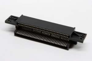
One easy, and more permanent solution to this problem is to replace the 72-pin edge connector inside the NES. With the connectors costing around US$10 on eBay and the replacement being a simple task for anyone with basic mechanical skills, it could also be considered good preventative maintenance for a NES which is just beginning to fail.
Here I'll explain the steps I use to replace the 72-pin edge connector in NES' whenever I work on them.
The original photos used for building this tutorial can be found here.
Parts and Tools Needed
Because the original NES was developed before Nintendo began to use tamper-resistant screws on its consoles, a simple Phillips-head screwdriver can open the enclosure. Of course, a replacement 72-pin edge connector is also needed. These can easily be acquired via eBay.
Replacement Steps
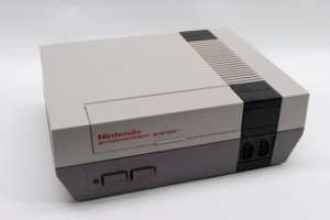 |
Start with the NES on a clean, accessible workstation. |
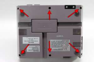 |
Turn the NES over and remove the indicated six screws from the bottom in order to open the enclosure. |
 |
Return the NES to it's normal position and lift the top cover off. |
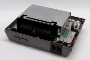 |
With the top cover of the NES removed the upper RF shield must now be removed. |
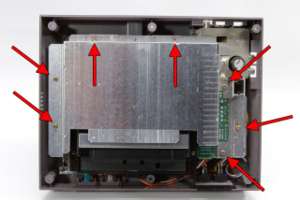 |
Remove the seven indicated screws to allow the upper RF shield to come loose. |
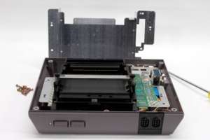 |
Lift the top RF shield off of the NES PCB. |
 |
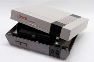
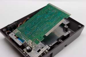
Removing the top RF shield reveals the NES cartridge mechanism. |
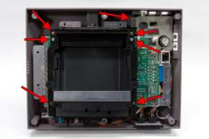 |
Remove the remain seven screws indicated to detach the main NES PCB and cartridge mechanism from the enclosure. Make note of the silver screws and their location. |
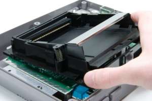 |
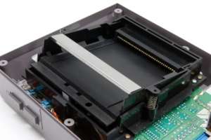
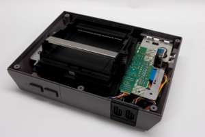
Slide the NES cartridge mechanism slightly forward, then lift it up and slide it away from the PCB. |
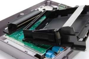 |
The NES cartridge mechanism should slide right off of the NES 72-pin edge connector. |
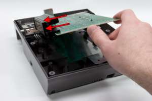 |
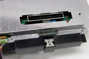
Gently lift up the PCB to make the 72-pin edge connector easily accessible, then remove the connector by pushing it in the direction of the arrows. |
 |
Here is the main NES PCB with the edge connector removed. |
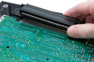 |
Push the new 72-pin edge connector on to the edge of the NES PCB. |
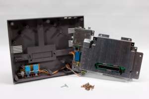 |
After the replacement 72-pin edge connector is fitted to the NES PCB, ensure that the bottom shielding from inside the case is fit properly to the PCB, especially around the bottom connector. |
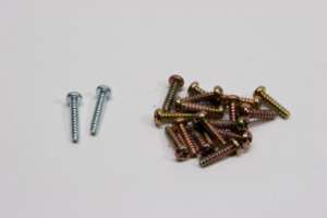 |
All screws removed from the NES for edge (72-pin) connector replacement are the same size and color, except for the two silver screws from the cartridge mechanism. Be sure the silver screws go back where they belong. |
 |
When fitting the cartridge mechanism back on to the PCB, be sure to slide the bottom lip of it beneath the PCB, else things will not fit together properly. Also note the proper fitting of the bottom RF shield around the bottom connector. |
 |
Close everything back up and replace all the screws in their original locations. Be careful not to tighten them too much as they could strip the holes or break the mounts. |
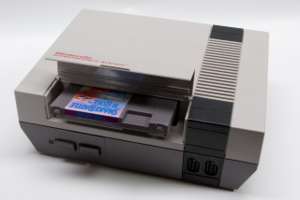 |
With the NES reassembled it's time to play some games! |