 |
For the last two or three works the ceiling fan in my bedroom hasn’t been responding to signals sent by the remote control leaving us with only a dim table lamp to illuminate the room. Not long after cleaning the contacts in the remote the fan would occasionally fail to respond to signals from the remote unless its power was cycled by the light switch under the remote holder. After flipping the switch off then on it would then work for a few days before needing another reset, but this failing state only lasted for a few weeks before the system simply failed leaving neither the light nor fan usable.
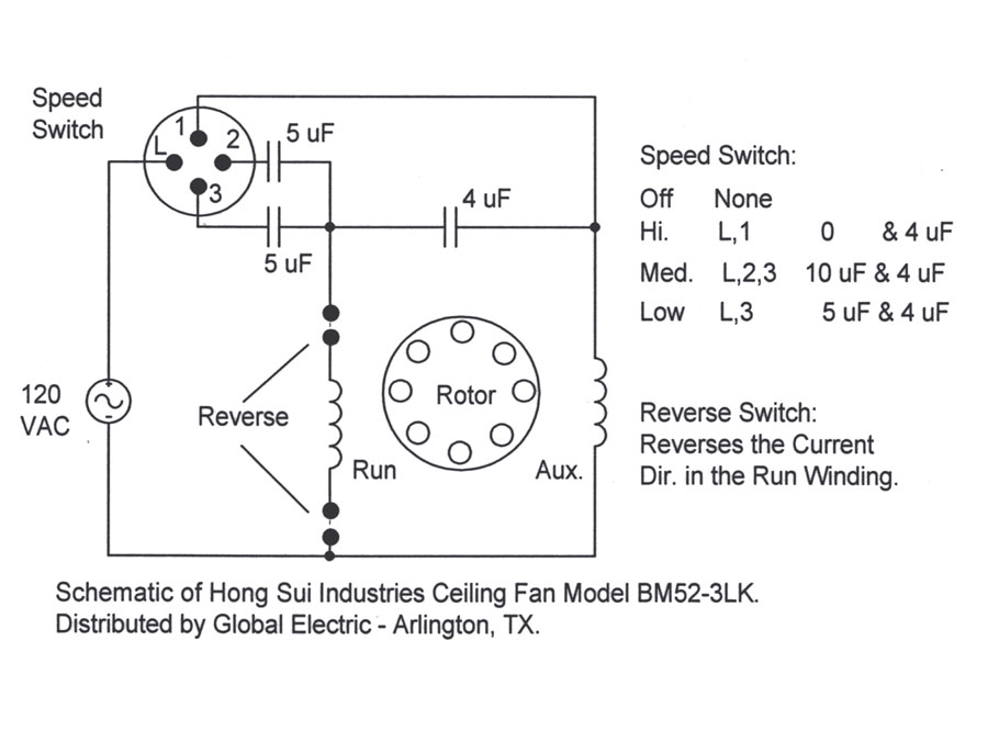
Frustrated by this I decided to bypass the wireless entirely and switch the unit to a typical fan/light dual switch setup on the wall. I figured that the light kit and fan motor itself were still fine so I set to work eliminating the failed fan control module. Having a spare dual-switch for the wall and a third (red) wire already between the electrical boxes made the house wiring part easy, but I still had some work to do modifying the fan. By reading Ken L. Klaser’s article Ceiling Fan Capacitor Solutions I was able to understand the basics of fan speed control, but this this schematic which he linked to was most helpful.
After looking over the control board to understand how the wires to the two coils in the motor were connected I came up with this schematic of how I felt the fan would be powered when set to run slow and in reverse. Removing the capacitors and building a test assembly showed that my initial thought was right, and this resulted in my building the assembly shown above. The fan now runs in reverse and on slow speed when powered and the wireless circuitry has found its place in the trash.
I could have purchased a new selector switch and capacitor assembly to have variable speeds and fitted both it and DPDT switch into the housing to offer the original control selection, but throughout its life the fan was almost exclusively used on low and in reverse, so I didn’t see the need. The fan also looks as it originally did with no new switches sticking out of the side or bits hanging off. I may add these selectors in the future if they are needed, but I don’t see that happening. Thus this was a $0 modification, costing only a few hours of time to learn something new and then redo the wiring.
(Yes, I realize that I should have used a longer piece of clear shrink tubing to better facilitate potting the ends. By the time I realized this I had most of the harness together and decided that simple stress relief and a bit of insulation should be sufficient.)
15 Comments